US5662869A - Exhaust gas purification method and apparatus therefor - Google Patents
Exhaust gas purification method and apparatus therefor Download PDFInfo
- Publication number
- US5662869A US5662869A US08/638,852 US63885296A US5662869A US 5662869 A US5662869 A US 5662869A US 63885296 A US63885296 A US 63885296A US 5662869 A US5662869 A US 5662869A
- Authority
- US
- United States
- Prior art keywords
- exhaust gas
- adsorbent
- catalyst
- hydrocarbon compounds
- gas purification
- Prior art date
- Legal status (The legal status is an assumption and is not a legal conclusion. Google has not performed a legal analysis and makes no representation as to the accuracy of the status listed.)
- Expired - Fee Related
Links
Images


Classifications
-
- F—MECHANICAL ENGINEERING; LIGHTING; HEATING; WEAPONS; BLASTING
- F01—MACHINES OR ENGINES IN GENERAL; ENGINE PLANTS IN GENERAL; STEAM ENGINES
- F01N—GAS-FLOW SILENCERS OR EXHAUST APPARATUS FOR MACHINES OR ENGINES IN GENERAL; GAS-FLOW SILENCERS OR EXHAUST APPARATUS FOR INTERNAL-COMBUSTION ENGINES
- F01N3/00—Exhaust or silencing apparatus having means for purifying, rendering innocuous, or otherwise treating exhaust
- F01N3/08—Exhaust or silencing apparatus having means for purifying, rendering innocuous, or otherwise treating exhaust for rendering innocuous
- F01N3/0807—Exhaust or silencing apparatus having means for purifying, rendering innocuous, or otherwise treating exhaust for rendering innocuous by using absorbents or adsorbents
- F01N3/0828—Exhaust or silencing apparatus having means for purifying, rendering innocuous, or otherwise treating exhaust for rendering innocuous by using absorbents or adsorbents characterised by the absorbed or adsorbed substances
- F01N3/0835—Hydrocarbons
-
- B—PERFORMING OPERATIONS; TRANSPORTING
- B01—PHYSICAL OR CHEMICAL PROCESSES OR APPARATUS IN GENERAL
- B01D—SEPARATION
- B01D53/00—Separation of gases or vapours; Recovering vapours of volatile solvents from gases; Chemical or biological purification of waste gases, e.g. engine exhaust gases, smoke, fumes, flue gases, aerosols
- B01D53/02—Separation of gases or vapours; Recovering vapours of volatile solvents from gases; Chemical or biological purification of waste gases, e.g. engine exhaust gases, smoke, fumes, flue gases, aerosols by adsorption, e.g. preparative gas chromatography
- B01D53/04—Separation of gases or vapours; Recovering vapours of volatile solvents from gases; Chemical or biological purification of waste gases, e.g. engine exhaust gases, smoke, fumes, flue gases, aerosols by adsorption, e.g. preparative gas chromatography with stationary adsorbents
- B01D53/0454—Controlling adsorption
-
- B—PERFORMING OPERATIONS; TRANSPORTING
- B01—PHYSICAL OR CHEMICAL PROCESSES OR APPARATUS IN GENERAL
- B01D—SEPARATION
- B01D53/00—Separation of gases or vapours; Recovering vapours of volatile solvents from gases; Chemical or biological purification of waste gases, e.g. engine exhaust gases, smoke, fumes, flue gases, aerosols
- B01D53/34—Chemical or biological purification of waste gases
- B01D53/92—Chemical or biological purification of waste gases of engine exhaust gases
- B01D53/94—Chemical or biological purification of waste gases of engine exhaust gases by catalytic processes
- B01D53/944—Simultaneously removing carbon monoxide, hydrocarbons or carbon making use of oxidation catalysts
-
- B—PERFORMING OPERATIONS; TRANSPORTING
- B01—PHYSICAL OR CHEMICAL PROCESSES OR APPARATUS IN GENERAL
- B01D—SEPARATION
- B01D53/00—Separation of gases or vapours; Recovering vapours of volatile solvents from gases; Chemical or biological purification of waste gases, e.g. engine exhaust gases, smoke, fumes, flue gases, aerosols
- B01D53/34—Chemical or biological purification of waste gases
- B01D53/92—Chemical or biological purification of waste gases of engine exhaust gases
- B01D53/94—Chemical or biological purification of waste gases of engine exhaust gases by catalytic processes
- B01D53/9481—Catalyst preceded by an adsorption device without catalytic function for temporary storage of contaminants, e.g. during cold start
- B01D53/9486—Catalyst preceded by an adsorption device without catalytic function for temporary storage of contaminants, e.g. during cold start for storing hydrocarbons
-
- B—PERFORMING OPERATIONS; TRANSPORTING
- B01—PHYSICAL OR CHEMICAL PROCESSES OR APPARATUS IN GENERAL
- B01D—SEPARATION
- B01D53/00—Separation of gases or vapours; Recovering vapours of volatile solvents from gases; Chemical or biological purification of waste gases, e.g. engine exhaust gases, smoke, fumes, flue gases, aerosols
- B01D53/34—Chemical or biological purification of waste gases
- B01D53/92—Chemical or biological purification of waste gases of engine exhaust gases
- B01D53/94—Chemical or biological purification of waste gases of engine exhaust gases by catalytic processes
- B01D53/9495—Controlling the catalytic process
-
- F—MECHANICAL ENGINEERING; LIGHTING; HEATING; WEAPONS; BLASTING
- F01—MACHINES OR ENGINES IN GENERAL; ENGINE PLANTS IN GENERAL; STEAM ENGINES
- F01N—GAS-FLOW SILENCERS OR EXHAUST APPARATUS FOR MACHINES OR ENGINES IN GENERAL; GAS-FLOW SILENCERS OR EXHAUST APPARATUS FOR INTERNAL-COMBUSTION ENGINES
- F01N13/00—Exhaust or silencing apparatus characterised by constructional features
- F01N13/009—Exhaust or silencing apparatus characterised by constructional features having two or more separate purifying devices arranged in series
-
- F—MECHANICAL ENGINEERING; LIGHTING; HEATING; WEAPONS; BLASTING
- F01—MACHINES OR ENGINES IN GENERAL; ENGINE PLANTS IN GENERAL; STEAM ENGINES
- F01N—GAS-FLOW SILENCERS OR EXHAUST APPARATUS FOR MACHINES OR ENGINES IN GENERAL; GAS-FLOW SILENCERS OR EXHAUST APPARATUS FOR INTERNAL-COMBUSTION ENGINES
- F01N3/00—Exhaust or silencing apparatus having means for purifying, rendering innocuous, or otherwise treating exhaust
- F01N3/08—Exhaust or silencing apparatus having means for purifying, rendering innocuous, or otherwise treating exhaust for rendering innocuous
- F01N3/0807—Exhaust or silencing apparatus having means for purifying, rendering innocuous, or otherwise treating exhaust for rendering innocuous by using absorbents or adsorbents
- F01N3/0814—Exhaust or silencing apparatus having means for purifying, rendering innocuous, or otherwise treating exhaust for rendering innocuous by using absorbents or adsorbents combined with catalytic converters, e.g. NOx absorption/storage reduction catalysts
-
- F—MECHANICAL ENGINEERING; LIGHTING; HEATING; WEAPONS; BLASTING
- F01—MACHINES OR ENGINES IN GENERAL; ENGINE PLANTS IN GENERAL; STEAM ENGINES
- F01N—GAS-FLOW SILENCERS OR EXHAUST APPARATUS FOR MACHINES OR ENGINES IN GENERAL; GAS-FLOW SILENCERS OR EXHAUST APPARATUS FOR INTERNAL-COMBUSTION ENGINES
- F01N3/00—Exhaust or silencing apparatus having means for purifying, rendering innocuous, or otherwise treating exhaust
- F01N3/08—Exhaust or silencing apparatus having means for purifying, rendering innocuous, or otherwise treating exhaust for rendering innocuous
- F01N3/0807—Exhaust or silencing apparatus having means for purifying, rendering innocuous, or otherwise treating exhaust for rendering innocuous by using absorbents or adsorbents
- F01N3/0871—Exhaust or silencing apparatus having means for purifying, rendering innocuous, or otherwise treating exhaust for rendering innocuous by using absorbents or adsorbents using means for controlling, e.g. purging, the absorbents or adsorbents
-
- F—MECHANICAL ENGINEERING; LIGHTING; HEATING; WEAPONS; BLASTING
- F01—MACHINES OR ENGINES IN GENERAL; ENGINE PLANTS IN GENERAL; STEAM ENGINES
- F01N—GAS-FLOW SILENCERS OR EXHAUST APPARATUS FOR MACHINES OR ENGINES IN GENERAL; GAS-FLOW SILENCERS OR EXHAUST APPARATUS FOR INTERNAL-COMBUSTION ENGINES
- F01N3/00—Exhaust or silencing apparatus having means for purifying, rendering innocuous, or otherwise treating exhaust
- F01N3/08—Exhaust or silencing apparatus having means for purifying, rendering innocuous, or otherwise treating exhaust for rendering innocuous
- F01N3/10—Exhaust or silencing apparatus having means for purifying, rendering innocuous, or otherwise treating exhaust for rendering innocuous by thermal or catalytic conversion of noxious components of exhaust
- F01N3/18—Exhaust or silencing apparatus having means for purifying, rendering innocuous, or otherwise treating exhaust for rendering innocuous by thermal or catalytic conversion of noxious components of exhaust characterised by methods of operation; Control
- F01N3/20—Exhaust or silencing apparatus having means for purifying, rendering innocuous, or otherwise treating exhaust for rendering innocuous by thermal or catalytic conversion of noxious components of exhaust characterised by methods of operation; Control specially adapted for catalytic conversion
- F01N3/2006—Periodically heating or cooling catalytic reactors, e.g. at cold starting or overheating
-
- F—MECHANICAL ENGINEERING; LIGHTING; HEATING; WEAPONS; BLASTING
- F01—MACHINES OR ENGINES IN GENERAL; ENGINE PLANTS IN GENERAL; STEAM ENGINES
- F01N—GAS-FLOW SILENCERS OR EXHAUST APPARATUS FOR MACHINES OR ENGINES IN GENERAL; GAS-FLOW SILENCERS OR EXHAUST APPARATUS FOR INTERNAL-COMBUSTION ENGINES
- F01N9/00—Electrical control of exhaust gas treating apparatus
-
- F—MECHANICAL ENGINEERING; LIGHTING; HEATING; WEAPONS; BLASTING
- F02—COMBUSTION ENGINES; HOT-GAS OR COMBUSTION-PRODUCT ENGINE PLANTS
- F02D—CONTROLLING COMBUSTION ENGINES
- F02D41/00—Electrical control of supply of combustible mixture or its constituents
- F02D41/02—Circuit arrangements for generating control signals
- F02D41/021—Introducing corrections for particular conditions exterior to the engine
- F02D41/0235—Introducing corrections for particular conditions exterior to the engine in relation with the state of the exhaust gas treating apparatus
- F02D41/027—Introducing corrections for particular conditions exterior to the engine in relation with the state of the exhaust gas treating apparatus to purge or regenerate the exhaust gas treating apparatus
-
- B—PERFORMING OPERATIONS; TRANSPORTING
- B01—PHYSICAL OR CHEMICAL PROCESSES OR APPARATUS IN GENERAL
- B01D—SEPARATION
- B01D2251/00—Reactants
- B01D2251/10—Oxidants
- B01D2251/102—Oxygen
-
- B—PERFORMING OPERATIONS; TRANSPORTING
- B01—PHYSICAL OR CHEMICAL PROCESSES OR APPARATUS IN GENERAL
- B01D—SEPARATION
- B01D2253/00—Adsorbents used in seperation treatment of gases and vapours
- B01D2253/10—Inorganic adsorbents
- B01D2253/106—Silica or silicates
- B01D2253/108—Zeolites
-
- B—PERFORMING OPERATIONS; TRANSPORTING
- B01—PHYSICAL OR CHEMICAL PROCESSES OR APPARATUS IN GENERAL
- B01D—SEPARATION
- B01D2255/00—Catalysts
- B01D2255/20—Metals or compounds thereof
- B01D2255/207—Transition metals
-
- F—MECHANICAL ENGINEERING; LIGHTING; HEATING; WEAPONS; BLASTING
- F01—MACHINES OR ENGINES IN GENERAL; ENGINE PLANTS IN GENERAL; STEAM ENGINES
- F01N—GAS-FLOW SILENCERS OR EXHAUST APPARATUS FOR MACHINES OR ENGINES IN GENERAL; GAS-FLOW SILENCERS OR EXHAUST APPARATUS FOR INTERNAL-COMBUSTION ENGINES
- F01N2250/00—Combinations of different methods of purification
- F01N2250/12—Combinations of different methods of purification absorption or adsorption, and catalytic conversion
-
- F—MECHANICAL ENGINEERING; LIGHTING; HEATING; WEAPONS; BLASTING
- F01—MACHINES OR ENGINES IN GENERAL; ENGINE PLANTS IN GENERAL; STEAM ENGINES
- F01N—GAS-FLOW SILENCERS OR EXHAUST APPARATUS FOR MACHINES OR ENGINES IN GENERAL; GAS-FLOW SILENCERS OR EXHAUST APPARATUS FOR INTERNAL-COMBUSTION ENGINES
- F01N2370/00—Selection of materials for exhaust purification
- F01N2370/22—Selection of materials for exhaust purification used in non-catalytic purification apparatus
- F01N2370/24—Zeolitic material
-
- F—MECHANICAL ENGINEERING; LIGHTING; HEATING; WEAPONS; BLASTING
- F01—MACHINES OR ENGINES IN GENERAL; ENGINE PLANTS IN GENERAL; STEAM ENGINES
- F01N—GAS-FLOW SILENCERS OR EXHAUST APPARATUS FOR MACHINES OR ENGINES IN GENERAL; GAS-FLOW SILENCERS OR EXHAUST APPARATUS FOR INTERNAL-COMBUSTION ENGINES
- F01N2570/00—Exhaust treating apparatus eliminating, absorbing or adsorbing specific elements or compounds
- F01N2570/16—Oxygen
-
- F—MECHANICAL ENGINEERING; LIGHTING; HEATING; WEAPONS; BLASTING
- F01—MACHINES OR ENGINES IN GENERAL; ENGINE PLANTS IN GENERAL; STEAM ENGINES
- F01N—GAS-FLOW SILENCERS OR EXHAUST APPARATUS FOR MACHINES OR ENGINES IN GENERAL; GAS-FLOW SILENCERS OR EXHAUST APPARATUS FOR INTERNAL-COMBUSTION ENGINES
- F01N3/00—Exhaust or silencing apparatus having means for purifying, rendering innocuous, or otherwise treating exhaust
- F01N3/08—Exhaust or silencing apparatus having means for purifying, rendering innocuous, or otherwise treating exhaust for rendering innocuous
- F01N3/10—Exhaust or silencing apparatus having means for purifying, rendering innocuous, or otherwise treating exhaust for rendering innocuous by thermal or catalytic conversion of noxious components of exhaust
- F01N3/18—Exhaust or silencing apparatus having means for purifying, rendering innocuous, or otherwise treating exhaust for rendering innocuous by thermal or catalytic conversion of noxious components of exhaust characterised by methods of operation; Control
- F01N3/20—Exhaust or silencing apparatus having means for purifying, rendering innocuous, or otherwise treating exhaust for rendering innocuous by thermal or catalytic conversion of noxious components of exhaust characterised by methods of operation; Control specially adapted for catalytic conversion
-
- F—MECHANICAL ENGINEERING; LIGHTING; HEATING; WEAPONS; BLASTING
- F01—MACHINES OR ENGINES IN GENERAL; ENGINE PLANTS IN GENERAL; STEAM ENGINES
- F01N—GAS-FLOW SILENCERS OR EXHAUST APPARATUS FOR MACHINES OR ENGINES IN GENERAL; GAS-FLOW SILENCERS OR EXHAUST APPARATUS FOR INTERNAL-COMBUSTION ENGINES
- F01N3/00—Exhaust or silencing apparatus having means for purifying, rendering innocuous, or otherwise treating exhaust
- F01N3/08—Exhaust or silencing apparatus having means for purifying, rendering innocuous, or otherwise treating exhaust for rendering innocuous
- F01N3/10—Exhaust or silencing apparatus having means for purifying, rendering innocuous, or otherwise treating exhaust for rendering innocuous by thermal or catalytic conversion of noxious components of exhaust
- F01N3/24—Exhaust or silencing apparatus having means for purifying, rendering innocuous, or otherwise treating exhaust for rendering innocuous by thermal or catalytic conversion of noxious components of exhaust characterised by constructional aspects of converting apparatus
- F01N3/30—Arrangements for supply of additional air
-
- F—MECHANICAL ENGINEERING; LIGHTING; HEATING; WEAPONS; BLASTING
- F02—COMBUSTION ENGINES; HOT-GAS OR COMBUSTION-PRODUCT ENGINE PLANTS
- F02B—INTERNAL-COMBUSTION PISTON ENGINES; COMBUSTION ENGINES IN GENERAL
- F02B1/00—Engines characterised by fuel-air mixture compression
- F02B1/02—Engines characterised by fuel-air mixture compression with positive ignition
- F02B1/04—Engines characterised by fuel-air mixture compression with positive ignition with fuel-air mixture admission into cylinder
-
- Y—GENERAL TAGGING OF NEW TECHNOLOGICAL DEVELOPMENTS; GENERAL TAGGING OF CROSS-SECTIONAL TECHNOLOGIES SPANNING OVER SEVERAL SECTIONS OF THE IPC; TECHNICAL SUBJECTS COVERED BY FORMER USPC CROSS-REFERENCE ART COLLECTIONS [XRACs] AND DIGESTS
- Y02—TECHNOLOGIES OR APPLICATIONS FOR MITIGATION OR ADAPTATION AGAINST CLIMATE CHANGE
- Y02T—CLIMATE CHANGE MITIGATION TECHNOLOGIES RELATED TO TRANSPORTATION
- Y02T10/00—Road transport of goods or passengers
- Y02T10/10—Internal combustion engine [ICE] based vehicles
- Y02T10/12—Improving ICE efficiencies
-
- Y—GENERAL TAGGING OF NEW TECHNOLOGICAL DEVELOPMENTS; GENERAL TAGGING OF CROSS-SECTIONAL TECHNOLOGIES SPANNING OVER SEVERAL SECTIONS OF THE IPC; TECHNICAL SUBJECTS COVERED BY FORMER USPC CROSS-REFERENCE ART COLLECTIONS [XRACs] AND DIGESTS
- Y02—TECHNOLOGIES OR APPLICATIONS FOR MITIGATION OR ADAPTATION AGAINST CLIMATE CHANGE
- Y02T—CLIMATE CHANGE MITIGATION TECHNOLOGIES RELATED TO TRANSPORTATION
- Y02T10/00—Road transport of goods or passengers
- Y02T10/10—Internal combustion engine [ICE] based vehicles
- Y02T10/40—Engine management systems
Definitions
- the present invention relates to an exhaust gas purification method and apparatus therefor, and more specifically, to an exhaust gas purification method and apparatus therefor capable of effectively purifying harmful compounds present in an exhaust gas, in particular, hydrocarbon and the like produced in a large amount at the cold start-up of engine.
- HC hydrocarbon
- an electric heated catalyst hereinafter, referred to as an EHC
- an adsorbent mainly composed of zeolite in an exhaust gas pipe.
- a technique using the EHC is disclosed, for example, in U.S. Pat. No. 5,063,029 for a catalyst converter previously filed by the applicant.
- the EHC is energized by a battery power supply to heat forcibly and steeply a catalyst on a heater or a main catalyst disposed on a downstream side.
- This disclosed technique is very effective to reduce the emission of HC at the cold start-up of engine.
- Japanese Patent Application Laid-Open No. 75327/1990 discloses an automobile exhaust gas purification apparatus comprising a catalyst for purifying harmful compounds in an exhaust gas disposed in an exhaust gas system and Y type zeolite or mordenite disposed upstream of the catalyst. Further, Japanese Patent Application Laid-Open No. 135126/1990 discloses an automobile exhaust gas purification apparatus comprising an exhaust gas purification catalyst disposed in an exhaust gas system and an adsorbent disposed up-stream of the catalyst, the adsorbent including at least one kind of catalyst metal carried at a portion of a monolith carrier coated with zeolite.
- Japanese Patent Application Laid-Open No. 56247/1990 discloses an exhaust gas purification catalyst containing zeolite which comprises a first catalyst layer mainly composed of zeolite and disposed on a carrier and a second catalyst layer mainly composed of a noble metal catalyst with an oxidation/reduction ability and disposed on the first catalyst layer.
- EP485179 proposed by the applicant discloses a technique made by combining an EHC and adsorbent.
- This technique includes a catalyst converter for purifying exhaust gas by the combination of an adsorbent or adsorbent-catalyst -composition coated on a heater or an adsorbent composed of a high-silica zeolite having a Si/Al ratio of at least 40 and a catalyst carried by the zeolite and main monolith catalyst and honeycomb heater.
- Japanese Patent Application Laid-Open No. 75327/1990 describes that when an exhaust gas has a temperature of 300° C. or lower, HC is adsorbed by the adsorbent in a trapper, and when the exhaust gas has a temperature exceeding 300° C., the HC is desorbed from the adsorbent and flows into a catalyst converter and is purified by a catalyst.
- zeolite capable keeping the HC up to 300° C. is not available now and even C 3 H 6 capable of adsorbing HC at a relatively high temperature violently causes the desorption of the HC at 200° C.
- the exhaust gas is activated and thus a large amount of unpurified HC is exhausted.
- Japanese Patent Applications Laid-Open Nos. 75327/1990 and 135126/1990 indicate that Y type and mordenite type are preferable as a type of the zeolite mainly constituting the absorbent, these types of zeolite have a poor heat resistance and insufficient durability because the zeolite contains a large amount of Al 2 O 3 .
- the catalyst disclosed in Japanese Patent Application Laid-Open No. 56247/1990 intends to serve a three-way catalyst having a high purification ability of HC in particular at the cold start-up of engine and when an air-fuel ratio is in a rich region, a resulting purification ability is not high because the characteristics at the cold start-up of engine are not investigated and a specific operation method is not executed.
- EP485179 discloses feeding secondary air at a rate of 200 1/min for 50 seconds after engine start-up as operating conditions, this is premised on that an EHC is used. However, the use of the EHC itself does not solve the above problem caused in the system.
- an object of the present invention is to provide an exhaust gas purification method and apparatus therefor capable of effectively purifying harmful compounds present in an exhaust gas, in particular, HC and the like produced in a large amount at the cold start-up of an engine without the need for a complex system such as an EHC, bypass system and the like.
- an exhaust gas purification method which comprises the steps of: using an exhaust gas purification system including an adsorbent containing an adsorbent element capable of adsorbing harmful compounds such as hydrocarbon and the like in an exhaust gas and a catalyst containing a catalyst element for lowering the harmful compounds in the exhaust gas each disposed in the exhaust gas pipe of an internal combustion engine; and adding an oxidizing gas to the exhaust gas or regulating amounts of combustion air and fuel, for a given period, in the process in which the hydrocarbon and the like in the exhaust gas produced at the cold start-up of the internal combustion engine are adsorbed by the adsorbent and desorbed from the adsorbent as a temperature of the adsorbent is increased by the exhaust gas to provide thereby an exhaust gas component containing excessive oxygen whereby the desorbed hydrocarbon and the like are oxidized on the catalyst.
- an exhaust gas purification method which comprises the steps of: using an exhaust gas purification system including a catalyst-adsorbent containing an absorbent element capable of adsorbing harmful compounds such as hydrocarbon and the like in an exhaust gas and a catalyst element for lowering the harmful compounds in the exhaust gas and disposed in the exhaust gas pipe of an internal combustion engine, and further provided with a catalyst containing a catalyst element and disposed in the exhaust gas pipe, when necessary; and adding an oxidizing gas to the exhaust gas or regulating amounts of combustion air and fuel, for a given period, in the process in which the hydrocarbon and the like in the exhaust gas produced at the cold start-up of the internal combustion engine are adsorbed by the catalyst-adsorbent and desorbed from the catalyst-adsorbent as a temperature of the catalyst-adsorbent is increased by the exhaust gas to provide thereby an exhaust gas component containing excessive oxygen whereby the desorbed hydrocarbon and the like are oxidized on the catalyst-adsorbent and on the catalyst
- an exhaust gas purification apparatus which comprises an adsorbent containing an adsorbent element capable of adsorbing harmful compounds such as hydrocarbon and the like in an exhaust gas, a catalyst containing a catalyst element for lowering the harmful compounds in the exhaust gas and an oxidizing gas feed means or a means for regulating amounts of combustion air and fuel to provide an exhaust gas component containing excessive oxygen located upstream of the adsorbent and/or the catalyst, each of which is disposed in the exhaust gas pipe of an internal combustion engine.
- an exhaust gas purification apparatus which comprises a catalyst-adsorbent containing an adsorbent element capable of absorbing harmful compounds such as hydrocarbon and the like in an exhaust gas and a catalyst element for lowering the harmful compounds in the exhaust gas, a catalyst containing catalyst element further provided when necessary and an oxidizing gas feed means or a means for regulating amounts of combustion air and fuel to provide an exhaust gas component containing excessive oxygen located upstream of the catalyst-adsorbent and/or the catalyst, each of which is disposed in the exhaust gas pipe of an internal combustion engine.
- the oxidizing gas includes a fluid and the like containing ozone and O 2 -- in addition to secondary air.
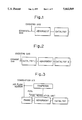
- FIG. 1 is a diagram showing an example of arrangement of an exhaust gas purification apparatus according to the present invention
- FIG. 2 is a diagram showing an example of arrangement of an exhaust gas purification apparatus according to the present invention.
- FIG. 3 is a diagram showing an example of arrangement of an exhaust gas purification apparatus according to the present invention.
- FIG. 4 is a diagram showing an example of arrangement of an exhaust gas purification apparatus according to the present invention.
- FIG. 5 is a diagram showing an example of arrangement of an exhaust gas purification apparatus according to the present invention.
- FIG. 6 is a graph showing values of HC emitted at respective cold start-up of an engine and changing as time elapsed which were obtained as a result of an FTP test performed by using an adsorbent composed of a cordierite carrier and a zeolite component coated thereon;
- FIG. 7 is a graph showing values of HC emitted at respective cold start-up of engine and changing as time elapsed which were obtained as a result of Example 3 and Comparative Example 3.
- FIG. 8 is a graph showing accumulated values of HC emitted at respective cold start-up of an engine and changing as time elapsed which were obtained as a result of Example 3 and Comparative Example 3.
- the structure of the adsorbent, catalyst and catalyst-adsorbent used in an exhaust gas purification method and apparatus therefor of the present invention is not specifically limited, and any of a bead, pellet, honeycomb, ring and the like may be arbitrarily used.
- a honeycomb structure composed of cordierite or ferrite type stainless steel having a catalyst element and/or adsorbent element coated thereon is preferably used. Since a catalyst reaction and adsorption are effected at a relatively high speed, when the honeycomb structure is used, its geometrical surface area must be increased, and thus it preferably has a cell density of at least 100 cells/in 2 .
- one or a plurality of the honeycomb structures may be used as a carrier and one or a plurality of the honeycomb structures having the catalyst element and/or adsorbent element coated thereon are disposed in an exhaust gas pipe in the state that they are held in a can body to operate as an exhaust gas purification apparatus.
- a catalyst element and adsorption element are carried by a single honeycomb carrier in coexistence
- a catalyst element and an adsorption element are respectively carried upstream and downstream of a honeycomb carrier or vice versa;
- catalyst elements are carried upstream of a plurality of honeycomb carriers and adsorption elements are carried downstream thereof, and vice versa: and (4) a catalyst element and adsorption element are carried by a plurality of honeycomb carriers by using the methods (1) and (2).
- the method (1) in which the catalyst element and adsorption element coexist is preferable because when HC and the like are desorbed, they can be smoothly purified by the catalyst element.
- zeolite Although zeolite, activated charcoal and the like are available as the adsorption element capable of adsorbing harmful compounds such as HC and the like, a heat resistance of at least 500° C. is needed to dispose an adsorbent in an exhaust gas system, and thus zeolite is preferably used.
- Zeolite may be any of a natural product and synthetic product and its kind is not particularly specified, but preferably used is zeolite containing SiO 2 /Al 2 O 3 with a mole ratio of at least 20 and more preferably at least 80 from the view point of heat resistance, durability and hydrophobic property. More specifically, ZSM-5, USY, ⁇ -zeolite, silicalite, metallosilicate and the like can be preferably used.
- zeolite not only one kind of zeolite but also several kinds thereof may be used in combination.
- ZMS-5 having relatively fine micro pores of about 0.55 nm is advantageous for the adsorption of small molecules such as propene and the like, whereas it is disadvantageous for the adsorption of large molecules such as toluene and xylene.
- USY having relatively large micro pores of about 0.74 nm is disadvantageous for the adsorption of small molecules such as propene and the like, whereas it is advantageous for the adsorption of large molecules such as toluene, xylene and the like. Therefore, it is one of preferable methods to coat the honeycomb structure with the mixture of ZSM-5 and USY.
- ZSM-5 and USY may be separately carried against a gas flow, and in this case ZSM-5 is preferably carried on an upstream side because it can keep its adsorption ability up to a relatively high temperature of 150° C.
- ⁇ -zeolite is a preferable absorbent because it has bimodal fine pores of about 0.55 nm and 0.70 nm and can adsorb both of small molecules and large molecules relatively well.
- preferable adsorption characteristics can be obtained by arbitrarily combining ⁇ -zeolite or ZSM-5 and USY and further ⁇ -zeolite, ZSM-5 and USY.
- zeolite may be independently used as the absorption element, it is preferable to carry one or more kinds of noble metals such as Pt, Pd, Rh and the like thereof to control coking occurred in parallel with the adsorption of HC and the like, whereby the adsorption element can be regenerated without lowering the adsorption ability of the zeolite.
- noble metals such as Pt, Pd, Rh and the like thereof
- Pd is preferably used as the noble metal carried into zeolite because it is cheapest and has a high regenerating ability.
- An ion exchange method is preferable as a method of carrying the noble metal from the view point of thermal stability.
- an amount of the noble metal to be carried is preferably 5-40 g/ft 3 (in a honeycomb volume) from the view point of cost and regenerating ability.
- an inorganic binder of Al 2 O 3 or SiO 2 may be contained in an amount of 5-20 wt %, when necessary. With this arrangement, the zeolite can be strongly carried without lowering an adsorption capacity to HC and the like.
- the present invention arranges a catalyst-adsorbent by separately adding a durable catalyst element or disposes a honeycomb structure and the like on which a catalyst element is carried as a catalyst.
- the catalyst element included in the catalyst-adsorbent or catalyst must contain at least one kind of metal selected from Group VIII elements, V, Cr, Mn, Cu, Mo, Ag, W, Re and Au and preferably contains at least one kind of a noble metal such as Pt, Pd, Rh and the like so that the catalyst-adsorbent or catalyst lights-off at a low temperature of about 200° C. when HC and the like are desorbed.
- a noble metal such as Pt, Pd, Rh and the like so that the catalyst-adsorbent or catalyst lights-off at a low temperature of about 200° C. when HC and the like are desorbed.
- Any one of the catalyst-adsorbent and catalyst in the exhaust gas purification system preferably contains Rh from the view point of the usual activity at a high temperature and, in particular, an ability for purifying NO x .
- any one of the catalyst-adsorbent and catalyst preferably contains Pd to improve the low temperature light-off performance of an exhaust gas containing excessive oxygen.
- these noble metals are used by being carried on a heat resistant oxide such as Al 2 O 3 , SiO 2 , TiO 2 , ZrO 2 or the like or composite oxide thereof.
- a heat resistant oxide such as Al 2 O 3 , SiO 2 , TiO 2 , ZrO 2 or the like or composite oxide thereof.
- Al 2 O 3 with a specific surface area of 100 m 2 /g or more is used, the noble metal is highly dispersedly carried and thus preferable because the low temperature light-off performance and heat resistance thereof are improved.
- the heat resistant oxide is preferably added with 5-30 wt % of oxide having an oxygen storing ability such as CeO 2 , La 2 O 3 --ZrO 2 or the like because the usual activity thereof is improved by it.
- a total amount the carried noble metal in the catalyst-adsorbent or catalyst is 20-130 g/ft 3 and an amount of carried Rh is preferably in the range of from 2 to 30 g/ft 3 .
- the catalyst-adsorbent is a layer-type catalyst-adsorbent composed of a honeycomb structure having a surface layer coated with a first layer of a high-silica containing zeolite such as ZSM-5, USY, ⁇ -zeolite or the like with a noble metal carried thereon and a second layer composed of composite oxide of Al 2 O 3 --CeO 2 with a noble metal carried thereon and coated on the first layer.
- a layer-type catalyst-adsorbent composed of a honeycomb structure having a surface layer coated with a first layer of a high-silica containing zeolite such as ZSM-5, USY, ⁇ -zeolite or the like with a noble metal carried thereon and a second layer composed of composite oxide of Al 2 O 3 --CeO 2 with a noble metal carried thereon and coated on the first layer.
- the Al 2 O 3 mainly constituting the second layer serves as a predryer for selectively adsorbing H 2 O contained in an exhaust gas at the cold start-up of engine and increases the adsorption of HC and the like executed by the first layer.
- the catalyst-adsorbent is heated from the second layer containing the catalyst element on the surface layer side, and thus when the HC and the like adsorbed by the zeolite component of the first layer are desorbed, the catalyst of the second layer suitably acts.
- honeycomb structure having a catalyst element on which a noble metal is carried and a zeolite component each carried thereon in a mixed state instead of being formed to layers acts fairly well.
- a weight ratio of the zeolite component to the catalyst element is 50-85:15-50 and the zeolite component is preferably contained in a larger amount.
- An amount of the zeolite component carried by the honeycomb structure is in the range of 0.05-0.25 g/cc and an amount of the catalyst element carried by the honeycomb structure is in the range of 0.02-0.20 g/cc.
- FIG. 1 shows an example of the apparatus including an adsorbent, catalyst, and oxidizing gas feed means. Since the adsorbent lacks of an ability for purifying desorbed HC and the like, the catalyst must be disposed downstream thereof.
- the oxidizing gas feed means is disposed upwardly of the adsorbent and/or catalyst.
- HC and the like produced in a large amount at the cold start-up of engine are adsorbed by the adsorbent once and then begin to desorb as the temperature of an exhaust gas is increased, an oxidizing gas is fed at this time and the exhaust gas is made to a composition containing excessive oxygen, and thus the catalyst exhibits an excellent purifying performance.
- the catalyst spaced excessively apart from the adsorbent causes a large heat loss, it is preferably located as near to the adsorbent as possible.
- An air pump or the like is preferably used as the oxidizing gas feed means.
- One of preferable examples to which the apparatus of FIG. 1 is applied is the one having a relatively small catalyst further disposed upstream of the adsorbent, as shown in FIG. 2.
- the temperature of an uppermost-stream catalyst I is increased more quickly than that of the catalyst II and lighted-off first under the existence of the oxidizing gas and, as a result, the desorption of HC and the like from the adsorbent is accelerated, whereby the light-off of the catalyst II is accelerated by the heat produced by the oxidization of the HC and CO contained in the exhaust gas as compared with the apparatus shown in FIG. 1 so that the desorbed HC and the like can be purified by the catalyst II.
- the oxidizing gas feed means is preferably located on the uppermost-stream side. Further, even if any one of the arrangements shown in FIGS. 1 and 2 is employed, it is preferable to contain Rh in any of the catalysts as a catalyst element to maintain a three-way reaction at a high temperature.
- the apparatus shown in FIG. 3 basically belongs to the same example as that shown in FIG. 1, this apparatus is used to propose another apparatus for obtaining an exhaust gas composition containing excessive oxygen, wherein an amount of flow of combustion air is read by an air flow sensor and an amount of fuel to be supplied is controlled by a computer through a fuel regulation unit so that an exhaust gas composition, for example, on a lean side is obtained for a given period.
- FIG. 4 shows an example in which only a catalyst-adsorbent is disposed in an exhaust gas pipe.
- HC and the like produced at the cold start-up of engine are adsorbed once by the catalyst element of the catalyst-adsorbent and begin to desorb as the temperature of an exhaust gas is increased. Since, however, an oxidizing gas is fed at this time, the catalyst element of the catalyst-adsorbent sufficiently acts and exhibits a preferable purification ability.
- Rh is preferably contained as a catalyst element of the catalyst-absorbent from the view point of the ability for purifying NO x
- Pd is preferably contained as a catalyst element thereof from the view point of light-off at a low temperature.
- the catalyst-adsorbent may be arbitrarily located at any position in the exhaust gas pipe, it is preferably located at a position relatively near to an engine exhaust port.
- an amount of adsorption of HC and the like is reduced and they begin to desorb in a relatively short time, whereas the catalyst is also lighted-off in a short time.
- the catalyst-adsorbent is located apart from the engine exhaust port such as, for example, under a floor, an amount of adsorption of HC and the like is increased and they are desorbed for a long time and further the catalyst acts with a considerable delay.
- a process for adsorption, desorption and reaction is preferably completed at the cold start-up of an engine when an engine is cooled with a less amount of emission of NO x and thus the catalyst-adsorbent is preferably located relatively near to the engine exhaust port.
- a mounting position is preferably such a position where adsorption is completed within 140 seconds of Bag 1 (within first mode of Bag 1) and further almost all of HC and the like desorb, when, for example, a honeycomb structure coated only with an adsorption element is disposed in an exhaust gas pipe and an adsorption/desorption curve is measured by preforming an FTP test.
- a catalyst may be also disposed downstream of a catalyst-adsorbent when necessary as shown in FIG. 5 as an example to which the apparatus shown in FIG. 4 is applied.
- the position where the oxidizing gas is fed is disposed upstream of the catalyst-adsorbent and/or catalyst, it is preferably disposed at the uppermost-stream side from the view point of activating the catalyst-adsorbent and catalyst in a shortest possible time.
- an area including the catalyst element is increased as compared with that shown in FIG. 4, and further even if HC and the like desorbed by the catalyst-adsorbent are not partially purified, they are purified by the catalyst on the downstream side, and thus this arrangement is more preferable.
- the exhaust gas purification method it is important to start the feed of an oxidizing gas prior to the desorption of HC and the like from the adsorbent or catalyst-adsorbent.
- the adsorbent or catalyst-adsorbent is disposed, for example, in the vicinity of an engine exhaust port, i.e., at the position of a manifold in an FTP test performed at a normal temperature (25° C.)
- HC and the like begin to desorb in about 30-40 seconds, it suffices to feed the oxidizing gas prior to the occurrence of the desorption.
- the effect of the feed is not changed even if the feed of the oxidizing gas begins substantially at the same time as engine cranking.
- the feed of the oxidizing gas is preferably stopped within one cycle of acceleration/deceleration of Bag 1, i.e., within 140 seconds, taking its rebound to the emission of NO x . Further, it is more preferable to stop the feed of the oxidizing gas after an O 2 sensor is operated and before a feedback control is carried out.
- an oxidizing gas feed hole is preferably located downstream of the O 2 sensor. Although different depending upon an engine capacity and a type of the engine, a given amount or variable amount of the oxidizing gas is fed so that an air/fuel ratio of 14.0 or more (a weak reduction side) is achieved or the air/fuel ratio is shifted to a lean side of 14.6-19.0 (an oxidizing side from a stoichiometric point).
- the same effect can be also obtained by an engine operation method, that is, a method of obtaining an exhaust gas composition including excessive oxygen by adjusting amounts of combustion air and fuel, in addition to the method of feeding the oxidizing gas.
- the engine operation method includes, for example, a method of feeding an amount of fuel a little less than a theoretical amount with respect to an amount of air sensed through an air flow sensor or the like by an open loop control (without using an O 2 sensor) after an engine is ignited; a method of controlling an amount of fuel, for example, to a lean side by a computer for a given period by using the O 2 sensor; and further a method of controlling an amount of fuel to a lean side for a given period by using a PEGO sensor or the like by which an output from the sensor is linearly changed depending upon an air/fuel ratio.
- the exhaust gas composition containing excessive oxygen described here means a composition shifted to an oxygen excessive side with respect to the composition of an exhaust gas obtained at the cold start-up of a usual engine not provided with a specific control means.
- an air/fuel ratio of 14.0 or more is achieved or the air/fuel ratio is shifted to a lean side of 14.6-19.0 (an oxidizing side from a stoichiometric point).
- the oxidizing ability of the catalyst-adsorbent and/or catalyst is greatly activated by the shift to the lean side as described above.
- the air/fuel ratio of these fuels is shifted to a lean side so that the same value as above is achieved by converting aforesaid air/fuel ratio by a stoichiometric ratio
- An in-line 4 type test vehicle with a displacement of 2000 cc was used and the aforesaid adsorbents (2.4 liters in total) were set at the position apart from an engine exhaust port by 350 mm and an FTP test was performed.
- FIG. 6 shows amounts of HC emitted at the cold start-up of engine and changing as time elapsed which were obtained by the present test. Note, the results obtained by using a cordierite carrier of 2.4 liters not coated with an adsorbent are also shown in FIG. 6 for comparison.
- HC is adsorbed by the adsorbents for about 40 seconds after engine cranking and thereafter shifts to desorption;
- an amount of emission from the adsorbents is smaller than an amount of emission from the cordierite carrier up to the point where the emission curve of the cordierite carrier intersects the emission curve of the adsorbents, that is, for 70 seconds.
- the adsorbents effectively act for this period;
- the Pt carrying Al 2 O 3 .CeO 2 powder in an amount of 0.15 g/cc was first carried by a cordierite carrier (5.66 inch dia., 6 mil/400 cpi 2 , 1.7 liters) as a first catalyst layer, then the Rh carrying Al 2 O 3 .CeO 2 powder in an amount of 0.05 g/cc was coated on and carried by the first catalyst layer as a second catalyst layer and finally they were fired at 500° C. to prepare a catalyst.
- a test vehicle was used in the same way as the evaluation of the adsorbents and the aforesaid adsorbents (2.4 liters in total) were set at the position apart from an engine exhaust port by 350 mm and further the aforesaid catalyst was set at the position apart from the engine exhaust port, by 850 mm so that the catalyst was located relatively adjacent to the adsorbents.
- Secondary air was fed from the position 100 mm upstream of the adsorbents by an air pump at a rate of 160 l/min for 100 seconds after engine cranking, and then the FTP test was performed. Note, although an air-fuel ratio exhibited a value of 12.5-13.5 before the feed of the secondary air, it exhibited a value of 15.0-17.5 after the feed of the secondary air. Table 1 shows resulting emission values.
- a catalyst-adsorbent composed of a first layer (inner layer) containing a zeolite component exhibiting a HC adsorption ability and a second layer (surface layer) containing a catalyst element exhibiting an ability as a three-way catalyst was prepared by causing the catalyst element to be carried by the adsorbents A and B shown in Example 1 in the following procedure.
- ⁇ -Al 2 O 3 with a specific surface area of 200 m 2 /g was added with cerium acetate and cerium oxide in an amount of 30 wt % when converted to oxide and ground in a wet state, followed by drying and calcining at 550° C. to obtain ⁇ -Al 2 O 3 .CeO 2 composite oxide.
- Noble metals Pt, Rh and Pd were impregnated into the resulting composite oxide, respectively, by using aqueous solutions containing H 2 PtCl 6 , Rh(NO 3 ) 3 , and (NH 4 ) 3 PdCl 2 , followed by drying and firing at 500° C. to obtain three kinds of noble metal carrying Al 2 O 3 .CeO 2 powder.
- a slight amount of water and acetic acid were added to the three kinds of the noble metal carrying Al 2 O 3 .CeO 2 powder to prepare three kinds of slurry to be carried.
- the above adsorbents A and B were immersed into the slurry to carry 0.05 g/cc of the catalyst element to the surface layer thereof, followed by drying and firing at 500° C. to obtain a catalyst-adsorbent.
- Example 1 Only the above catalyst-adsorbent was set to the same position as that of Example 1 (a catalyst was not provided on a downstream side) and evaluated by the same method as that of Example 1. Table 1 shows resulting emission values.
- Example 2 The same catalyst-adsorbent as that of Example 2 was used in place of the adsorbent of Example 1 and evaluation was performed by the same method as that of Example 1 (a catalyst was provided on a downstream side).
- Table 1 shows the emission values
- FIG. 7 shows amounts of HC changing as time elapsed
- FIG. 8 shows integrated emission values at the cold start-up of engine in this case, respectively.
- the FTP test was performed by using the same purification system as that of Example 1 and starting the feed of secondary air in 20 seconds after engine cranking.
- Example 3 The same purification system as that of Example 3 was used, an amount of combustion was sensed by a mass flow sensor and an adjustment was executed so that operation was carried out by shifting an air/fuel ratio to a lean side for 100 seconds in 20 seconds after engine cranking. Note, the air/fuel ratio exhibited a value 14.6-15.2 during this period. Table 1 shows resulting emission values.
- Evaluation was performed by using the same purification system as that of Example 3 without feeding secondary air and without employing any particular processing for shifting a value of the air/fuel ratio to a lean side.
- Table 1 shows resulting emission values.
- Example 3 Evaluation was performed by the same way as that of Example 3 except that a three-way catalyst of 2.41 (not containing a zeolite component) was used in place of the catalyst-adsorbent to confirm a catalyst volume increasing effect.
- FIGS. 7 and 8 and Table 1 show the result of the evaluation.
Landscapes
- Engineering & Computer Science (AREA)
- Chemical & Material Sciences (AREA)
- Combustion & Propulsion (AREA)
- Mechanical Engineering (AREA)
- General Engineering & Computer Science (AREA)
- Chemical Kinetics & Catalysis (AREA)
- General Chemical & Material Sciences (AREA)
- Health & Medical Sciences (AREA)
- Oil, Petroleum & Natural Gas (AREA)
- Analytical Chemistry (AREA)
- Environmental & Geological Engineering (AREA)
- Biomedical Technology (AREA)
- Toxicology (AREA)
- Materials Engineering (AREA)
- Exhaust Gas After Treatment (AREA)
- Exhaust Gas Treatment By Means Of Catalyst (AREA)
- Solid-Sorbent Or Filter-Aiding Compositions (AREA)
- Treating Waste Gases (AREA)
Priority Applications (2)
| Application Number | Priority Date | Filing Date | Title |
|---|---|---|---|
| US08/638,852 US5662869A (en) | 1992-12-06 | 1996-04-29 | Exhaust gas purification method and apparatus therefor |
| US08/919,359 US5887422A (en) | 1992-12-06 | 1997-08-28 | Exhaust gas purification method and apparatus therefor |
Applications Claiming Priority (5)
| Application Number | Priority Date | Filing Date | Title |
|---|---|---|---|
| JP4-335937 | 1992-12-06 | ||
| JP33593792A JP3311051B2 (ja) | 1992-12-16 | 1992-12-16 | 排気ガス浄化方法及び装置 |
| US878493A | 1993-01-27 | 1993-01-27 | |
| US28052994A | 1994-07-26 | 1994-07-26 | |
| US08/638,852 US5662869A (en) | 1992-12-06 | 1996-04-29 | Exhaust gas purification method and apparatus therefor |
Related Parent Applications (1)
| Application Number | Title | Priority Date | Filing Date |
|---|---|---|---|
| US28052994A Continuation | 1992-12-06 | 1994-07-26 |
Related Child Applications (1)
| Application Number | Title | Priority Date | Filing Date |
|---|---|---|---|
| US08/919,359 Division US5887422A (en) | 1992-12-06 | 1997-08-28 | Exhaust gas purification method and apparatus therefor |
Publications (1)
| Publication Number | Publication Date |
|---|---|
| US5662869A true US5662869A (en) | 1997-09-02 |
Family
ID=18294017
Family Applications (2)
| Application Number | Title | Priority Date | Filing Date |
|---|---|---|---|
| US08/638,852 Expired - Fee Related US5662869A (en) | 1992-12-06 | 1996-04-29 | Exhaust gas purification method and apparatus therefor |
| US08/919,359 Expired - Fee Related US5887422A (en) | 1992-12-06 | 1997-08-28 | Exhaust gas purification method and apparatus therefor |
Family Applications After (1)
| Application Number | Title | Priority Date | Filing Date |
|---|---|---|---|
| US08/919,359 Expired - Fee Related US5887422A (en) | 1992-12-06 | 1997-08-28 | Exhaust gas purification method and apparatus therefor |
Country Status (4)
| Country | Link |
|---|---|
| US (2) | US5662869A (de) |
| EP (2) | EP0948987A1 (de) |
| JP (1) | JP3311051B2 (de) |
| DE (1) | DE69328235T2 (de) |
Cited By (36)
| Publication number | Priority date | Publication date | Assignee | Title |
|---|---|---|---|---|
| US5768888A (en) * | 1996-11-08 | 1998-06-23 | Matros Technologies, Inc. | Emission control system |
| US5884473A (en) * | 1995-06-23 | 1999-03-23 | Ngk Insulators, Ltd. | System for exhaust gas purification and method for exhaust gas purification using said system |
| US5910293A (en) * | 1997-07-22 | 1999-06-08 | General Motors Corporation | Exhaust management system control |
| US5916129A (en) * | 1995-11-29 | 1999-06-29 | Bp Amoco Corporation | Control of exhaust emissions from an internal combustion engine |
| US5979157A (en) * | 1996-08-15 | 1999-11-09 | Toyota Jidosha Kabushiki Kaisha | Method and a device for purifying exhaust gas of an internal combustion engine |
| US6029441A (en) * | 1996-12-09 | 2000-02-29 | Ngk Insulators, Ltd. | Method for exhaust gas purification and system for exhaust gas purification used therein |
| US6047544A (en) * | 1997-08-20 | 2000-04-11 | Nissan Motor Co., Ltd. | Engine exhaust gas purification catalyst and exhaust gas purifier |
| US6058699A (en) * | 1996-11-19 | 2000-05-09 | Institut Francais Du Petrole | Exhaust gas depollution system and process |
| EP0914864A3 (de) * | 1997-10-28 | 2000-07-12 | Toyota Jidosha Kabushiki Kaisha | Kohlenwasserstoffadsorbant |
| WO2000059630A1 (en) * | 1998-07-10 | 2000-10-12 | Asec Manufacturing | Improved catalyzed adsorber system for treating internal combustion engine exhaust gas and method of making same |
| US6185933B1 (en) * | 1998-06-15 | 2001-02-13 | Nissan Motor Co., Ltd. | Exhaust emission control device for engine |
| US6235255B1 (en) | 1999-05-21 | 2001-05-22 | Asec Manufacturing | Catalyst support having zeolite with high sodium back ion-exchange capacity and catalysts made therefrom |
| US6334306B1 (en) * | 1998-05-29 | 2002-01-01 | Nissan Motor Co., Ltd. | Exhaust gas purification apparatus in combustion engine |
| US6387338B1 (en) | 2000-03-15 | 2002-05-14 | Delphi Technologies, Inc. | Preparation of multi-component Ce, Zr, Mox high oxygen-ion-conduct/oxygen-storage-capacity materials |
| US6539709B2 (en) * | 2000-05-02 | 2003-04-01 | Nissan Motor Co., Ltd. | Exhaust gas purifying system of internal combustion engine |
| US6641788B1 (en) * | 1997-07-02 | 2003-11-04 | Tosoh Corporation | Absorbent for a hydrocarbon, and exhaust gas-purifying catalyst |
| US20040060282A1 (en) * | 2002-10-01 | 2004-04-01 | Toyota Jidosha Kabushiki Kaisha | Secondary air supply system and secondary air supply method |
| US20040062698A1 (en) * | 2002-09-30 | 2004-04-01 | Flynn Harry E. | Reactor and process for reducing emissions of CO and NOx |
| US20040083716A1 (en) * | 2000-05-24 | 2004-05-06 | Twigg Martyn Vincent | Method of treating gasoline exhaust gases |
| US6750168B2 (en) * | 2000-12-05 | 2004-06-15 | Delphi Technologies, Inc. | High-temperature aging tolerance catalyzed adsorber system for treating internal combustion engine exhaust gas |
| US20040254061A1 (en) * | 2003-06-12 | 2004-12-16 | Danan Dou | Diesel exhaust emissions control device and methods of making thereof |
| US6863874B1 (en) * | 1998-10-12 | 2005-03-08 | Johnson Matthey Public Limited Company | Process and apparatus for treating combustion exhaust gas |
| US20050172614A1 (en) * | 2004-01-08 | 2005-08-11 | Mitsubishi Jidosha Kogyo Kabushiki Kaisha | Exhaust emission control device for an internal combustion engine |
| US20080159936A1 (en) * | 2006-12-27 | 2008-07-03 | Chevron U.S.A. Inc. | Treatment of cold start engine exhaust |
| US20080236144A1 (en) * | 2007-03-28 | 2008-10-02 | Denso Corporation | Control system of internal combustion engine and method for controlling the same |
| US20090000287A1 (en) * | 2007-05-15 | 2009-01-01 | Jared Dean Blaisdell | Exhaust Gas Flow Device |
| US20090010815A1 (en) * | 2007-07-06 | 2009-01-08 | Denso Corporation | Hexagonal-cell honeycomb catalyzer for purifying exhaust gas |
| US20100212301A1 (en) * | 2008-12-17 | 2010-08-26 | Korneel De Rudder | Flow Device for an Exhaust System |
| US20100282185A1 (en) * | 2008-01-17 | 2010-11-11 | L'air Liquide Societe Anonyme Pour L'etude Et L'exploitation Des Procedes Georges Claude | Burner and method for implementing an oxycombustion |
| US20110167810A1 (en) * | 2010-01-12 | 2011-07-14 | Lebas Jerome | Flow device for exhaust treatment system |
| US8938954B2 (en) | 2012-04-19 | 2015-01-27 | Donaldson Company, Inc. | Integrated exhaust treatment device having compact configuration |
| US9670811B2 (en) | 2010-06-22 | 2017-06-06 | Donaldson Company, Inc. | Dosing and mixing arrangement for use in exhaust aftertreatment |
| US9707525B2 (en) | 2013-02-15 | 2017-07-18 | Donaldson Company, Inc. | Dosing and mixing arrangement for use in exhaust aftertreatment |
| US10920634B2 (en) * | 2018-09-06 | 2021-02-16 | Toyota Jidosha Kabushiki Kaisha | Exhaust after treatment system |
| US11002204B2 (en) * | 2018-08-23 | 2021-05-11 | Toyota Jidosha Kabushiki Kaisha | Exhaust purification system of internal combustion engine and exhaust purification method |
| CN113813781A (zh) * | 2021-09-27 | 2021-12-21 | 南大恩洁优环境技术(江苏)股份公司 | 一种同时处理有机无机混合废气的净化装置及净化方法 |
Families Citing this family (42)
| Publication number | Priority date | Publication date | Assignee | Title |
|---|---|---|---|---|
| DE4419776B4 (de) * | 1993-06-23 | 2006-07-27 | Volkswagen Ag | Abgasanlage |
| CA2127478A1 (en) * | 1993-08-16 | 1995-02-17 | William Hertl | Modified zeolites for trapping hydrocarbons |
| US6667018B2 (en) * | 1994-07-05 | 2003-12-23 | Ngk Insulators, Ltd. | Catalyst-adsorbent for purification of exhaust gases and method for purification of exhaust gases |
| US5676912A (en) * | 1995-02-22 | 1997-10-14 | Mobil Oil Corporation | Process for exhaust gas NOx, CO, and hydrocarbon removal |
| AU705112B2 (en) * | 1995-06-06 | 1999-05-13 | Johnson Matthey Public Limited Company | Combatting air pollution |
| JP3830566B2 (ja) * | 1995-10-04 | 2006-10-04 | 日本碍子株式会社 | 排ガス浄化システム |
| DE19653910A1 (de) * | 1996-12-21 | 1998-06-25 | Daimler Benz Ag | Verfahren und Katalysator zur Verringerung von Schadstoffen in Gasen |
| JP3709953B2 (ja) * | 1997-09-12 | 2005-10-26 | 本田技研工業株式会社 | 内燃機関の排気浄化装置 |
| AU1930299A (en) * | 1997-12-24 | 1999-07-19 | Engelhard Corporation | Catalytic converter system for internal combustion engine powere d vehicles |
| DE19800665C1 (de) * | 1998-01-10 | 1999-07-01 | Degussa | Verfahren zum Betreiben eines Stickoxid-Speicherkatalysators |
| US6033638A (en) * | 1998-03-20 | 2000-03-07 | Campbell; Larry E. | Sequential adsorptive capture and catalytic oxidation of volatile organic compounds in a reactor bed |
| JPH11294142A (ja) * | 1998-04-14 | 1999-10-26 | Toyota Motor Corp | NOx浄化装置 |
| JP3722187B2 (ja) * | 1998-12-24 | 2005-11-30 | トヨタ自動車株式会社 | 吸着材の故障判定装置 |
| JP3376948B2 (ja) * | 1999-03-19 | 2003-02-17 | トヨタ自動車株式会社 | ハイブリット車の排気浄化制御装置 |
| FR2792967B1 (fr) * | 1999-04-27 | 2001-06-29 | Renault | Procede de commande de la richesse du melange air/carburant d'un moteur a combustion interne debitant des gaz d'echappement dans une ligne equipee d'un piege a hydrocarbures |
| US6560959B2 (en) * | 1999-12-06 | 2003-05-13 | Denso Corporation | Exhaust gas purification apparatus of internal combustion engine |
| US6632764B2 (en) * | 2000-01-19 | 2003-10-14 | Volkswagen Ag | Method for controlling the regeneration of an NOx storage converter |
| JP3716738B2 (ja) | 2000-11-06 | 2005-11-16 | 日産自動車株式会社 | 内燃機関の排気浄化装置 |
| JP3608516B2 (ja) * | 2001-01-16 | 2005-01-12 | トヨタ自動車株式会社 | 車輌のhc排出抑制運転方法 |
| US6813883B1 (en) * | 2001-02-14 | 2004-11-09 | Ford Global Technologies, Llc | System and method for controlling engine air/fuel ratio during hydrocarbon trap purging |
| JP3855266B2 (ja) * | 2001-11-01 | 2006-12-06 | 日産自動車株式会社 | 排気ガス浄化用触媒 |
| JP2004092535A (ja) * | 2002-08-30 | 2004-03-25 | Mitsubishi Motors Corp | 排ガス浄化装置 |
| JP2004108320A (ja) * | 2002-09-20 | 2004-04-08 | Isuzu Motors Ltd | 排気ガス浄化方法及びそのシステム |
| JP4225126B2 (ja) * | 2003-06-11 | 2009-02-18 | 日産自動車株式会社 | エンジンの排気ガス浄化装置 |
| DE102004032287B4 (de) * | 2004-07-02 | 2007-01-11 | J. Eberspächer GmbH & Co. KG | Abgasanlage |
| US20060153747A1 (en) * | 2005-01-13 | 2006-07-13 | Carrier Corporation | Gas treatment adsorption-oxidation system |
| JP4254751B2 (ja) | 2005-06-17 | 2009-04-15 | トヨタ自動車株式会社 | 排気ガス浄化装置 |
| JP4872637B2 (ja) * | 2006-12-08 | 2012-02-08 | マツダ株式会社 | 排気ガス浄化触媒の機能回復装置及び機能回復方法 |
| JP2008150980A (ja) * | 2006-12-15 | 2008-07-03 | Mazda Motor Corp | 排気ガス浄化装置 |
| JP4867655B2 (ja) * | 2006-12-28 | 2012-02-01 | トヨタ自動車株式会社 | 内燃機関の排気ガス浄化装置 |
| JP2008163871A (ja) | 2006-12-28 | 2008-07-17 | Toyota Motor Corp | 内燃機関の排気ガス浄化装置 |
| JP4453700B2 (ja) | 2006-12-28 | 2010-04-21 | トヨタ自動車株式会社 | 内燃機関の排気ガス浄化装置 |
| JP4497158B2 (ja) | 2006-12-28 | 2010-07-07 | トヨタ自動車株式会社 | 内燃機関の排気ガス浄化装置 |
| JP2008190364A (ja) * | 2007-02-01 | 2008-08-21 | Toyota Motor Corp | 内燃機関の排気浄化装置 |
| DE102008058010B4 (de) * | 2008-11-19 | 2015-03-12 | Continental Automotive Gmbh | Verfahren und Vorrichtung zum Betreiben einer Brennkraftmaschine |
| JP2011085060A (ja) * | 2009-10-15 | 2011-04-28 | Toyota Central R&D Labs Inc | 内燃機関の排気浄化装置及び方法 |
| RU2406558C1 (ru) * | 2009-10-29 | 2010-12-20 | Общество с ограниченной ответственностью "ЭНВАЙРОКЕТ" | Адсорбент для удаления углеводородов из выхлопных газов автомобиля |
| DE102009060290A1 (de) * | 2009-12-23 | 2011-06-30 | Volkswagen AG, 38440 | Abgasreinigung bei Ottomotoren mit Direkteinspritzung unter Verwendung von Adsorbern mit Partikelabscheidefunktion |
| WO2012026045A1 (ja) * | 2010-08-23 | 2012-03-01 | トヨタ自動車株式会社 | 内燃機関の排気浄化装置 |
| RU2543168C2 (ru) * | 2011-09-07 | 2015-02-27 | Закрытое Акционерное Общество "Саровские Лаборатории", Российская Федерация, | Состав адсорбента для удаления токсичных веществ из выхлопных газов автомобиля и способ его изготовления |
| EP3077112B1 (de) * | 2013-12-06 | 2022-02-16 | Johnson Matthey Public Limited Company | Abgaskatalysator mit zwei verschiedenen palladium-molekularsiebkatalysatoren |
| EP3881932A1 (de) | 2015-06-29 | 2021-09-22 | Corning Incorporated | Poröser keramikkörper zur emissionsreduktion |
Citations (19)
| Publication number | Priority date | Publication date | Assignee | Title |
|---|---|---|---|---|
| US3699683A (en) * | 1971-04-05 | 1972-10-24 | Chemical Construction Corp | Engine exhaust emission control system |
| US3757521A (en) * | 1971-04-05 | 1973-09-11 | Chemical Construction Corp | Integrated engine exhaust emission control system |
| US3842600A (en) * | 1972-03-22 | 1974-10-22 | Nissan Motor | Exhaust cleaning apparatus for internal combustion engines |
| US3896616A (en) * | 1972-04-21 | 1975-07-29 | Engelhard Min & Chem | Process and apparatus |
| US4383408A (en) * | 1979-08-17 | 1983-05-17 | Toyota Jidosha Kogyo Kabushiki Kaisha | Exhaust gas purifying method of an internal combustion engine |
| US4522027A (en) * | 1983-02-21 | 1985-06-11 | Nissan Motor Company, Limited | Exhaust particle removal system for an internal combustion engine |
| JPH0256247A (ja) * | 1988-05-17 | 1990-02-26 | Toyota Motor Corp | 排気浄化用触媒 |
| JPH0275327A (ja) * | 1988-09-09 | 1990-03-15 | Toyota Motor Corp | 自動車排気ガス浄化装置 |
| JPH02135126A (ja) * | 1988-11-14 | 1990-05-24 | Toyota Motor Corp | 自動車排気ガス浄化装置 |
| DE4033827A1 (de) * | 1989-10-24 | 1991-05-23 | Nichias Corp | Abgasreinigungsvorrichtung fuer methanolgespeiste motoren |
| US5051244A (en) * | 1990-07-20 | 1991-09-24 | Uop | Use of a molecular sieve bed to minimize emissions during cold start of internal combustion engines |
| DE4008789A1 (de) * | 1990-03-19 | 1991-09-26 | Schatz Oskar | Verfahren und vorrichtung zur behandlung der abgase von verbrennungsmotoren |
| US5078979A (en) * | 1990-07-20 | 1992-01-07 | Uop | Molecular sieve bed/catalyst to treat automotive exhaust |
| US5159810A (en) * | 1991-08-26 | 1992-11-03 | Ford Motor Company | Catalytic converter monitoring using downstream oxygen sensor |
| US5184462A (en) * | 1991-03-19 | 1993-02-09 | Oskar Schatz | Method and an apparatus for the treatment of exhaust gas from an IC engine |
| FR2686375A1 (fr) * | 1992-01-17 | 1993-07-23 | Ecia Equip Composants Ind Auto | Ligne d'echappement des gaz de sortie d'un moteur notamment de vehicule automobile. |
| US5315824A (en) * | 1991-08-29 | 1994-05-31 | Toyota Jidosha Kabushiki Kaisha | Cold HC adsorption and removal apparatus for an internal combustion engine |
| EP0485179B1 (de) * | 1990-11-09 | 1995-05-10 | Ngk Insulators, Ltd. | Heizgerät und Katalysatoreinrichtung |
| US5447694A (en) * | 1992-10-20 | 1995-09-05 | Corning Incorporated | Exhaust gas conversion method and apparatus using thermally stable zeolites |
Family Cites Families (2)
| Publication number | Priority date | Publication date | Assignee | Title |
|---|---|---|---|---|
| US5142864A (en) * | 1991-09-30 | 1992-09-01 | Uop | Process for treating an engine exhaust stream employing a catalyst, an adsorbent bed and a turbocharger |
| JP3083599B2 (ja) * | 1991-09-30 | 2000-09-04 | 株式会社日立製作所 | 排気ガス浄化システム |
-
1992
- 1992-12-16 JP JP33593792A patent/JP3311051B2/ja not_active Expired - Fee Related
-
1993
- 1993-12-15 EP EP99111575A patent/EP0948987A1/de not_active Withdrawn
- 1993-12-15 DE DE69328235T patent/DE69328235T2/de not_active Expired - Fee Related
- 1993-12-15 EP EP93310145A patent/EP0602963B1/de not_active Expired - Lifetime
-
1996
- 1996-04-29 US US08/638,852 patent/US5662869A/en not_active Expired - Fee Related
-
1997
- 1997-08-28 US US08/919,359 patent/US5887422A/en not_active Expired - Fee Related
Patent Citations (20)
| Publication number | Priority date | Publication date | Assignee | Title |
|---|---|---|---|---|
| US3699683A (en) * | 1971-04-05 | 1972-10-24 | Chemical Construction Corp | Engine exhaust emission control system |
| US3757521A (en) * | 1971-04-05 | 1973-09-11 | Chemical Construction Corp | Integrated engine exhaust emission control system |
| US3842600A (en) * | 1972-03-22 | 1974-10-22 | Nissan Motor | Exhaust cleaning apparatus for internal combustion engines |
| US3896616A (en) * | 1972-04-21 | 1975-07-29 | Engelhard Min & Chem | Process and apparatus |
| US4383408A (en) * | 1979-08-17 | 1983-05-17 | Toyota Jidosha Kogyo Kabushiki Kaisha | Exhaust gas purifying method of an internal combustion engine |
| US4522027A (en) * | 1983-02-21 | 1985-06-11 | Nissan Motor Company, Limited | Exhaust particle removal system for an internal combustion engine |
| JPH0256247A (ja) * | 1988-05-17 | 1990-02-26 | Toyota Motor Corp | 排気浄化用触媒 |
| JPH0275327A (ja) * | 1988-09-09 | 1990-03-15 | Toyota Motor Corp | 自動車排気ガス浄化装置 |
| US4985210A (en) * | 1988-09-09 | 1991-01-15 | 501 Toyota Jidosha Kabushiki Kaisha | Exhaust gas purifying apparatus for automobile |
| JPH02135126A (ja) * | 1988-11-14 | 1990-05-24 | Toyota Motor Corp | 自動車排気ガス浄化装置 |
| DE4033827A1 (de) * | 1989-10-24 | 1991-05-23 | Nichias Corp | Abgasreinigungsvorrichtung fuer methanolgespeiste motoren |
| DE4008789A1 (de) * | 1990-03-19 | 1991-09-26 | Schatz Oskar | Verfahren und vorrichtung zur behandlung der abgase von verbrennungsmotoren |
| US5051244A (en) * | 1990-07-20 | 1991-09-24 | Uop | Use of a molecular sieve bed to minimize emissions during cold start of internal combustion engines |
| US5078979A (en) * | 1990-07-20 | 1992-01-07 | Uop | Molecular sieve bed/catalyst to treat automotive exhaust |
| EP0485179B1 (de) * | 1990-11-09 | 1995-05-10 | Ngk Insulators, Ltd. | Heizgerät und Katalysatoreinrichtung |
| US5184462A (en) * | 1991-03-19 | 1993-02-09 | Oskar Schatz | Method and an apparatus for the treatment of exhaust gas from an IC engine |
| US5159810A (en) * | 1991-08-26 | 1992-11-03 | Ford Motor Company | Catalytic converter monitoring using downstream oxygen sensor |
| US5315824A (en) * | 1991-08-29 | 1994-05-31 | Toyota Jidosha Kabushiki Kaisha | Cold HC adsorption and removal apparatus for an internal combustion engine |
| FR2686375A1 (fr) * | 1992-01-17 | 1993-07-23 | Ecia Equip Composants Ind Auto | Ligne d'echappement des gaz de sortie d'un moteur notamment de vehicule automobile. |
| US5447694A (en) * | 1992-10-20 | 1995-09-05 | Corning Incorporated | Exhaust gas conversion method and apparatus using thermally stable zeolites |
Non-Patent Citations (2)
| Title |
|---|
| SAE Technical Paper Serial No. 920847, Heimrich et al "Cold-Start Hydrocarbon Collection for Advances Exhaust Emission Control", Feb. 1992, pp. 1-12. |
| SAE Technical Paper Serial No. 920847, Heimrich et al Cold Start Hydrocarbon Collection for Advances Exhaust Emission Control , Feb. 1992, pp. 1 12. * |
Cited By (59)
| Publication number | Priority date | Publication date | Assignee | Title |
|---|---|---|---|---|
| US5884473A (en) * | 1995-06-23 | 1999-03-23 | Ngk Insulators, Ltd. | System for exhaust gas purification and method for exhaust gas purification using said system |
| US5916129A (en) * | 1995-11-29 | 1999-06-29 | Bp Amoco Corporation | Control of exhaust emissions from an internal combustion engine |
| US5979157A (en) * | 1996-08-15 | 1999-11-09 | Toyota Jidosha Kabushiki Kaisha | Method and a device for purifying exhaust gas of an internal combustion engine |
| US5768888A (en) * | 1996-11-08 | 1998-06-23 | Matros Technologies, Inc. | Emission control system |
| US6058699A (en) * | 1996-11-19 | 2000-05-09 | Institut Francais Du Petrole | Exhaust gas depollution system and process |
| US6029441A (en) * | 1996-12-09 | 2000-02-29 | Ngk Insulators, Ltd. | Method for exhaust gas purification and system for exhaust gas purification used therein |
| US6641788B1 (en) * | 1997-07-02 | 2003-11-04 | Tosoh Corporation | Absorbent for a hydrocarbon, and exhaust gas-purifying catalyst |
| US5910293A (en) * | 1997-07-22 | 1999-06-08 | General Motors Corporation | Exhaust management system control |
| US6047544A (en) * | 1997-08-20 | 2000-04-11 | Nissan Motor Co., Ltd. | Engine exhaust gas purification catalyst and exhaust gas purifier |
| EP0914864A3 (de) * | 1997-10-28 | 2000-07-12 | Toyota Jidosha Kabushiki Kaisha | Kohlenwasserstoffadsorbant |
| US6147023A (en) * | 1997-10-28 | 2000-11-14 | Toyota Jidosha Kabushiki Kaisha | Hydrocarbon-adsorbent |
| US6334306B1 (en) * | 1998-05-29 | 2002-01-01 | Nissan Motor Co., Ltd. | Exhaust gas purification apparatus in combustion engine |
| US6185933B1 (en) * | 1998-06-15 | 2001-02-13 | Nissan Motor Co., Ltd. | Exhaust emission control device for engine |
| WO2000059630A1 (en) * | 1998-07-10 | 2000-10-12 | Asec Manufacturing | Improved catalyzed adsorber system for treating internal combustion engine exhaust gas and method of making same |
| US6863874B1 (en) * | 1998-10-12 | 2005-03-08 | Johnson Matthey Public Limited Company | Process and apparatus for treating combustion exhaust gas |
| US6235255B1 (en) | 1999-05-21 | 2001-05-22 | Asec Manufacturing | Catalyst support having zeolite with high sodium back ion-exchange capacity and catalysts made therefrom |
| US6387338B1 (en) | 2000-03-15 | 2002-05-14 | Delphi Technologies, Inc. | Preparation of multi-component Ce, Zr, Mox high oxygen-ion-conduct/oxygen-storage-capacity materials |
| US6539709B2 (en) * | 2000-05-02 | 2003-04-01 | Nissan Motor Co., Ltd. | Exhaust gas purifying system of internal combustion engine |
| US20040083716A1 (en) * | 2000-05-24 | 2004-05-06 | Twigg Martyn Vincent | Method of treating gasoline exhaust gases |
| US6750168B2 (en) * | 2000-12-05 | 2004-06-15 | Delphi Technologies, Inc. | High-temperature aging tolerance catalyzed adsorber system for treating internal combustion engine exhaust gas |
| US7175821B2 (en) * | 2002-09-30 | 2007-02-13 | Tronox Llc | Reactor and process for reducing emissions of CO and NOx |
| US20040062698A1 (en) * | 2002-09-30 | 2004-04-01 | Flynn Harry E. | Reactor and process for reducing emissions of CO and NOx |
| US20040060282A1 (en) * | 2002-10-01 | 2004-04-01 | Toyota Jidosha Kabushiki Kaisha | Secondary air supply system and secondary air supply method |
| US6978600B2 (en) * | 2002-10-01 | 2005-12-27 | Toyota Jidosha Kabushiki Kaisha | Secondary air supply system and secondary air supply method |
| US20040254061A1 (en) * | 2003-06-12 | 2004-12-16 | Danan Dou | Diesel exhaust emissions control device and methods of making thereof |
| US20050172614A1 (en) * | 2004-01-08 | 2005-08-11 | Mitsubishi Jidosha Kogyo Kabushiki Kaisha | Exhaust emission control device for an internal combustion engine |
| US20080159936A1 (en) * | 2006-12-27 | 2008-07-03 | Chevron U.S.A. Inc. | Treatment of cold start engine exhaust |
| EP2099549A4 (de) * | 2006-12-27 | 2011-01-12 | Chevron Usa Inc | Behandlung von kaltstartabgasen |
| US9114362B2 (en) | 2006-12-27 | 2015-08-25 | Chevron U.S.A. Inc. | Treatment of cold start engine exhaust |
| US8580228B2 (en) | 2006-12-27 | 2013-11-12 | Chevron U.S.A. Inc. | Treatment of cold start engine exhaust |
| US20080236144A1 (en) * | 2007-03-28 | 2008-10-02 | Denso Corporation | Control system of internal combustion engine and method for controlling the same |
| US20090000287A1 (en) * | 2007-05-15 | 2009-01-01 | Jared Dean Blaisdell | Exhaust Gas Flow Device |
| US8915064B2 (en) | 2007-05-15 | 2014-12-23 | Donaldson Company, Inc. | Exhaust gas flow device |
| US7988921B2 (en) | 2007-07-06 | 2011-08-02 | Denso Corporation | Hexagonal-cell honeycomb catalyzer for purifying exhaust gas |
| US20090010815A1 (en) * | 2007-07-06 | 2009-01-08 | Denso Corporation | Hexagonal-cell honeycomb catalyzer for purifying exhaust gas |
| US20100282185A1 (en) * | 2008-01-17 | 2010-11-11 | L'air Liquide Societe Anonyme Pour L'etude Et L'exploitation Des Procedes Georges Claude | Burner and method for implementing an oxycombustion |
| US8499548B2 (en) | 2008-12-17 | 2013-08-06 | Donaldson Company, Inc. | Flow device for an exhaust system |
| US20100212301A1 (en) * | 2008-12-17 | 2010-08-26 | Korneel De Rudder | Flow Device for an Exhaust System |
| US9925502B2 (en) | 2008-12-17 | 2018-03-27 | Donaldson Company, Inc. | Flow device for an exhaust system |
| US9180407B2 (en) | 2008-12-17 | 2015-11-10 | Donaldson Company, Inc. | Flow device for an exhaust system |
| US20110167810A1 (en) * | 2010-01-12 | 2011-07-14 | Lebas Jerome | Flow device for exhaust treatment system |
| US8539761B2 (en) | 2010-01-12 | 2013-09-24 | Donaldson Company, Inc. | Flow device for exhaust treatment system |
| US9810126B2 (en) | 2010-01-12 | 2017-11-07 | Donaldson Company, Inc. | Flow device for exhaust treatment system |
| US9670811B2 (en) | 2010-06-22 | 2017-06-06 | Donaldson Company, Inc. | Dosing and mixing arrangement for use in exhaust aftertreatment |
| US10294841B2 (en) | 2010-06-22 | 2019-05-21 | Donaldson Company, Inc. | Dosing and mixing arrangement for use in exhaust aftertreatment |
| US11608764B2 (en) | 2010-06-22 | 2023-03-21 | Donaldson Company, Inc. | Dosing and mixing arrangement for use in exhaust aftertreatment |
| US10968800B2 (en) | 2010-06-22 | 2021-04-06 | Donaldson Company, Inc. | Dosing and mixing arrangement for use in exhaust aftertreatment |
| US8938954B2 (en) | 2012-04-19 | 2015-01-27 | Donaldson Company, Inc. | Integrated exhaust treatment device having compact configuration |
| US9598999B2 (en) | 2012-04-19 | 2017-03-21 | Donaldson Company, Inc. | Integrated exhaust treatment device having compact configuration |
| US10533477B2 (en) | 2012-04-19 | 2020-01-14 | Donaldson Company, Inc. | Integrated exhaust treatment device having compact configuration |
| US9458750B2 (en) | 2012-04-19 | 2016-10-04 | Donaldson Company, Inc. | Integrated exhaust treatment device having compact configuration |
| US10245564B2 (en) | 2013-02-15 | 2019-04-02 | Donaldson Company, Inc. | Dosing and mixing arrangement for use in exhaust aftertreatment |
| US10603642B2 (en) | 2013-02-15 | 2020-03-31 | Donaldson Company, Inc. | Dosing and mixing arrangement for use in exhaust aftertreatment |
| US11110406B2 (en) | 2013-02-15 | 2021-09-07 | Donaldson Company, Inc. | Dosing and mixing arrangement for use in exhaust aftertreatment |
| US9707525B2 (en) | 2013-02-15 | 2017-07-18 | Donaldson Company, Inc. | Dosing and mixing arrangement for use in exhaust aftertreatment |
| US11002204B2 (en) * | 2018-08-23 | 2021-05-11 | Toyota Jidosha Kabushiki Kaisha | Exhaust purification system of internal combustion engine and exhaust purification method |
| US10920634B2 (en) * | 2018-09-06 | 2021-02-16 | Toyota Jidosha Kabushiki Kaisha | Exhaust after treatment system |
| CN113813781A (zh) * | 2021-09-27 | 2021-12-21 | 南大恩洁优环境技术(江苏)股份公司 | 一种同时处理有机无机混合废气的净化装置及净化方法 |
| CN113813781B (zh) * | 2021-09-27 | 2023-03-10 | 南大恩洁优环境技术(江苏)股份公司 | 一种同时处理有机无机混合废气的净化装置及净化方法 |
Also Published As
| Publication number | Publication date |
|---|---|
| JPH06185343A (ja) | 1994-07-05 |
| EP0948987A1 (de) | 1999-10-13 |
| US5887422A (en) | 1999-03-30 |
| JP3311051B2 (ja) | 2002-08-05 |
| EP0602963A1 (de) | 1994-06-22 |
| DE69328235D1 (de) | 2000-05-04 |
| EP0602963B1 (de) | 2000-03-29 |
| DE69328235T2 (de) | 2000-09-28 |
Similar Documents
| Publication | Publication Date | Title |
|---|---|---|
| US5662869A (en) | Exhaust gas purification method and apparatus therefor | |
| CA2224043C (en) | Method for exhaust gas purification and system for exhaust gas purification used therein | |
| US5647203A (en) | Exhaust gas purification system and exhaust gas purification method | |
| EP0820810B1 (de) | Abgasreinigung | |
| US6518213B1 (en) | Exhaust gas purifying catalyst and process for preparing the catalyst | |
| US5078979A (en) | Molecular sieve bed/catalyst to treat automotive exhaust | |
| JP5590640B2 (ja) | 排気ガス浄化システム | |
| US5727385A (en) | Lean-burn nox catalyst/nox trap system | |
| EP0904827A1 (de) | Katalysator-Adsorbent zur Reinigung von Abgasen und Verfahren zur Reinigung von Abgasen | |
| EP0830201B1 (de) | Dieselmotorabgasreinigungssystem | |
| KR20110041502A (ko) | 린번 내연 엔진용 배기 시스템 | |
| EP0935055A2 (de) | Vorrichtung zur Reinigung von hochsauerstoffhaltigen Abgasen | |
| US20030039597A1 (en) | Close coupled catalyst with a SOx trap and methods of making and using the same | |
| US6602822B2 (en) | Catalyst for exhaust gas purification and exhaust gas purification system using the same | |
| EP0886041B1 (de) | Vorrichtung zur Reinigung von Abgasen | |
| US5950421A (en) | Tungsten-modified platinum NOx traps for automotive emission reduction | |
| EP0867218B1 (de) | Motor mit System zur Abgasreinigung | |
| CA2128562A1 (en) | Modified large pore zeolites for trapping alkenes | |
| US5531068A (en) | Combination catalyst/adsorber system for treating an engine exhaust gas stream | |
| EP0895803B1 (de) | Verwendung einer Vorrichtung zum Reinigen von Abgasen | |
| JP4058588B2 (ja) | 排気浄化用触媒 | |
| KR100610424B1 (ko) | 자동차 배기가스 정화용 다기능 다층 촉매와 그 제조방법 | |
| JP3661555B2 (ja) | 排気ガス浄化システム | |
| JPH11285624A (ja) | 自動車の排出物削減のための白金/アルミナ・窒素酸化物ト ラップの使用 |
Legal Events
| Date | Code | Title | Description |
|---|---|---|---|
| FEPP | Fee payment procedure |
Free format text: PAYOR NUMBER ASSIGNED (ORIGINAL EVENT CODE: ASPN); ENTITY STATUS OF PATENT OWNER: LARGE ENTITY |
|
| FPAY | Fee payment |
Year of fee payment: 4 |
|
| FPAY | Fee payment |
Year of fee payment: 8 |
|
| REMI | Maintenance fee reminder mailed | ||
| LAPS | Lapse for failure to pay maintenance fees | ||
| STCH | Information on status: patent discontinuation |
Free format text: PATENT EXPIRED DUE TO NONPAYMENT OF MAINTENANCE FEES UNDER 37 CFR 1.362 |
|
| FP | Lapsed due to failure to pay maintenance fee |
Effective date: 20090902 |