US5689934A - Method and system for wrapping a bale - Google Patents
Method and system for wrapping a bale Download PDFInfo
- Publication number
- US5689934A US5689934A US08/639,202 US63920296A US5689934A US 5689934 A US5689934 A US 5689934A US 63920296 A US63920296 A US 63920296A US 5689934 A US5689934 A US 5689934A
- Authority
- US
- United States
- Prior art keywords
- bale
- wrapping
- station
- arms
- carriage
- Prior art date
- Legal status (The legal status is an assumption and is not a legal conclusion. Google has not performed a legal analysis and makes no representation as to the accuracy of the status listed.)
- Expired - Fee Related
Links
- 238000000034 method Methods 0.000 title claims abstract description 21
- 239000000463 material Substances 0.000 claims abstract description 18
- 239000003381 stabilizer Substances 0.000 claims abstract description 8
- 230000014759 maintenance of location Effects 0.000 claims description 3
- 230000000087 stabilizing effect Effects 0.000 claims description 2
- 230000003213 activating effect Effects 0.000 claims 1
- 230000000712 assembly Effects 0.000 claims 1
- 238000000429 assembly Methods 0.000 claims 1
- 238000007789 sealing Methods 0.000 description 5
- 238000013459 approach Methods 0.000 description 2
- 239000002184 metal Substances 0.000 description 2
- 230000000717 retained effect Effects 0.000 description 2
- 230000006641 stabilisation Effects 0.000 description 2
- 238000011105 stabilization Methods 0.000 description 2
- 238000012546 transfer Methods 0.000 description 2
- 229920000742 Cotton Polymers 0.000 description 1
- 238000011109 contamination Methods 0.000 description 1
- 238000013016 damping Methods 0.000 description 1
- 239000000835 fiber Substances 0.000 description 1
- 239000012535 impurity Substances 0.000 description 1
- 238000004519 manufacturing process Methods 0.000 description 1
- 238000012986 modification Methods 0.000 description 1
- 230000004048 modification Effects 0.000 description 1
- 238000012858 packaging process Methods 0.000 description 1
- 239000010816 packaging waste Substances 0.000 description 1
- 229920000728 polyester Polymers 0.000 description 1
- 238000012545 processing Methods 0.000 description 1
- 230000001953 sensory effect Effects 0.000 description 1
Images


Classifications
-
- B—PERFORMING OPERATIONS; TRANSPORTING
- B65—CONVEYING; PACKING; STORING; HANDLING THIN OR FILAMENTARY MATERIAL
- B65B—MACHINES, APPARATUS OR DEVICES FOR, OR METHODS OF, PACKAGING ARTICLES OR MATERIALS; UNPACKING
- B65B11/00—Wrapping, e.g. partially or wholly enclosing, articles or quantities of material, in strips, sheets or blanks, of flexible material
- B65B11/02—Wrapping articles or quantities of material, without changing their position during the wrapping operation, e.g. in moulds with hinged folders
- B65B11/025—Wrapping articles or quantities of material, without changing their position during the wrapping operation, e.g. in moulds with hinged folders by webs revolving around stationary articles
-
- B—PERFORMING OPERATIONS; TRANSPORTING
- B65—CONVEYING; PACKING; STORING; HANDLING THIN OR FILAMENTARY MATERIAL
- B65B—MACHINES, APPARATUS OR DEVICES FOR, OR METHODS OF, PACKAGING ARTICLES OR MATERIALS; UNPACKING
- B65B2210/00—Specific aspects of the packaging machine
- B65B2210/14—Details of wrapping machines with web dispensers for application of a continuous web in layers onto the articles
- B65B2210/20—Details of wrapping machines with web dispensers for application of a continuous web in layers onto the articles the web dispenser being mounted on a rotary arm
Definitions
- the invention generally relates to a method and system for wrapping articles with a wrapping apparatus, and more particularly for wrapping a bale formed in a press, transferring the bale to a wrapping position where the bale is wrapped with a film supplied by a wrapping apparatus, and transferring the wrapped bale to a conveyor.
- bales Bulk quantities of materials like cotton, polyester and other fibers are often formed into bales with a press and the bale is inserted into a package, which prevents the bale from separating during shipping and processing.
- one or more generally opaque bags were disposed over the pressed bale to protect the bale from the environment, and then multiple retention straps were applied over the bagged bale with a strapping machine to retain the form of the bale.
- a first bag was unfolded over one end of the bale and a second bag was unfolded over an opposing end of the bale so that the first and second bags overlapped each other. The straps were then applied about the overlapping bags to retain the bale and to seal the overlapping bags.
- the present invention is drawn to a novel method and system for wrapping a bale supported on a platform in a wrapping position with a bale wrapping apparatus having a rotating arm positioned above the bale, a downright member extending downwardly from an outward end portion of the rotating arm, and a wrap carriage vertically movable upon the downright member, wherein the downright member and the wrap carriage orbit the bale in the wrapping position to apply a film or wrap material about the bale.
- the bale wrapping apparatus also includes a bale stabilizer, positioned above the bale in the wrapping position, having a plate extendable toward the bale to contact the bale during application of the wrap about the bale, and retractable away from the bale to permit rotation of the bale.
- An upender with laterally movable arms and pivoting paddles is positionable to engage or clamp opposing sides of the bale, and the upender is movable to raise the clamped bale from the platform.
- the paddles are pivotable to rotate the raised bale, which is then lowered back onto the platform.
- the arms are laterally movable to disengage the paddles from the rotated bale, and the upender is movable away from the bale to permit wrapping of the bale and transfer of bales to and away from the wrapping position.
- the upender includes a carriage movable up and down relative to a base.
- Each arm is pivotally coupled to the carriage by a second pivot assembly to laterally move the paddles toward and away from each other, and each arm is pivotally coupled to the carriage by a third pivot assembly to pivot the arms between a raised position and a lowered position.
- the upender may include a motor coupled to a drive wheel to move the upender toward and away from the bale.
- the platform for supporting the bale in the wrapping position is mounted on a dolly translatable between a bale press station wherein a bale is loadable onto the platform, the wrapping position, and a conveyor station wherein the bale is unloaded from the platform.
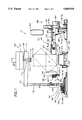
- FIG. 1 is a partial side view of a bale wrapping system according to an exemplary embodiment of the invention.
- FIG. 2 is a partial plan view of a bale wrapping system according to an exemplary embodiment of the invention.
- FIG. 3a is a partial front view of a carriage for an upender according to an exemplary embodiment of the invention.
- FIG. 3b is a partial front view of a base for an upender according to an exemplary embodiment of the invention.
- FIG. 3c is a partial front view of a pivot assembly for an upender according to an exemplary embodiment of the invention.
- FIG. 1 is a partial side view of a bale wrapping system 10 according to an exemplary embodiment of the invention.
- the system 10 generally comprises a bale wrapping apparatus 100 for applying wrap about a bale B, a platform 200 for supporting the bale B in a wrapping position, and an upender 300 for rotating the bale B at the wrapping position to permit application of wrapping on all sides of the rotated bale B.
- the platform 200 is mounted on a dolly that delivers an unwrapped bale B to the wrapping position for wrapping, and later removes the wrapped bale B from the wrapping position to make room for the next unwrapped bale B.
- the platform 200 may also be pivotally coupled to a dolly of the type disclosed in copending U.S. patent application Ser. No.
- the platform on this dolly is actuatable to an inclined position for loading a bale onto the platform, and the platform is lowered downwardly onto the dolly under the weight of the bale loaded or doffed onto the platform.
- a platform damping means applies a progressively increasing resistance to the platform as the platform is lowered onto the dolly to reduce any impact on the bale as the bale is doffed onto the inclined platform and as the platform is lowered onto the dolly.
- FIG. 2 is a partial plan view of an another exemplary embodiment including a bale station 400 for loading unwrapped bales B onto the platform 200 of the dolly, and a conveyor station 500 for unloading wrapped bales B from the platform 200 of the dolly wherein a single dolly is translatable back and forth between the bale station 400, the wrapping position 200 and the conveyor station 500.
- FIG. 2 shows an embodiment wherein the dolly is motor driven along a rail type track T between the stations 400 and 500 and the wrapping position 200.
- the dolly may include sensors 210, like metal sensors, that cooperate with metal flags 220 located along the track T for detecting the position of the dolly relative to the tracks T as shown in FIG. 1.
- a photo cell may alternatively be used for some applications.
- a series of one or more flags 220 may be located proximate the bale station 400, the wrap station below the bale apparatus 200, and the conveyor station 500 and are usable to generate signals as the dolly moves over the flags 220 to indicate the location of the dolly and to increase and decrease the speed of the dolly, to stop the movement of the dolly, and to raise the platform 200 as the dolly approaches the bale station 400.
- operation of the dolly is controlled by a programmable logic controller (PLC).
- PLC programmable logic controller
- several dollies operate around a circuit delivering unwrapped bales B from the bale station 400 to the wrapping position 200, and removing the wrapped bales B to the conveyor station 500.
- the bales are generally pressed and secured with strapping at the bale station 400 wherein the strapped bale B is transferred either directly or indirectly onto the dolly. In other embodiments, however, the bale B may be wrapped before application of the strapping.
- FIGS. 1 and 2 include side and plan views, respectively, of a wrapping apparatus of the type usable with the exemplary embodiment of the present invention, which in one embodiment is a CobraTM spiral film wrapping machine available from ITW Mima, an Illinois Tool Works Company, Boca Raton, Fla. Other wrapping machines however like the RingmasterTM horizontal wrapping ring machine available from Signode, an Illinois Tool Works Company, Glenview, Ill., may also be used with the wrapping system of the present invention.
- the bale wrapping apparatus generally includes an arm 110 rotatably coupled by a shaft 124 to a rotary drive member, like a variable speed motor not shown in the drawing, mounted and housed in a main frame 120 mounted over the bale wrapping position.
- the main frame 120 is generally supported by a ground based support frame, not shown in the drawing, or alternatively is suspended from the ceiling or mounted on a wall.
- a downright member 130 extends downwardly from an outward end portion 112 of the rotating arm 110 and supports a wrap carriage 140 that is translatable up and down the downright member 130.
- the wrap carriage 140 includes a roll of film, which may be a transparent stretch wrap type film, that is supplied under tension as the wrap carriage orbits the bale B. In one embodiment, the film is maintained at a constant tension by a drag brake coupled to feed a roller over which the film passes.
- the downright member 130 and wrap carriage 140 orbit about the bale B supported upon the platform 200 at the wrapping position, and the film is fed from the wrap carriage 140 and applied about the bale B.
- the wrap carriage 140 generally begins at a lower position on the downright 130 and moves upward as the wrap carriage 140 orbits the bale B to spiral wrap the bale B with the film and returns downward toward the bottom of the downright member 130 upon completion of the wrapping process wherein the film is cut and a tail end of the film is adhered to the bale B as further discussed below.
- a PLC may be used to provide integrated control of the dolly and the bale wrapping apparatus based on sensors that detect the angular position and rotation rate of the rotatable arm 110 and the position of the wrapping carriage 140 along the downright 130 among other sensory input.
- the wrapping apparatus 100 includes a wrap sealing apparatus 150 with a main carriage 152 mounted on the floor, which is translatable with a drive motor toward and away from the wrapping position 200 in the direction of arrows U T and U A along rails or other guide structure.
- An intermediate carriage 160 is pivotally mounted along axis A to a pivot support pivotally mounted along axis B to the main carriage 152.
- the intermediate carriage 160 is movable in the directions of arrows V L and V u between a lowered position and a first upright position by a first pneumatic or hydraulic actuator.
- FIG. 1 shows a portion of the intermediate carriage 160 in the first upright position.
- the intermediate carriage 160 includes a wrap clamp 162 for clamping a tail of the film, one or more heat sealing pads 164 for heat sealing a tail portion of the film to the bale B, and a film cutter, such as a hot wire, 166 for cutting the tail portion of the film.
- the intermediate carriage 160 is pivotal farther upward by a second pneumatic or hydraulic actuator to a second upright position wherein the heat pads 164 are raised to a level permitting the contact with the bale 4.
- the film tail is initially retained by the wrap clamp 162 and the main carriage is advanced toward the bale B in the wrapping position 200 where the intermediate carriage 160 is pivoted upright substantially as shown in FIG. 1. After the wrapping carriage 140 of the wrapping apparatus rotates about the bale B, beginning from the position shown in FIG.
- the clamp 162 releases the film tail and the intermediate carriage 160 is pivoted back to the lowered position.
- the intermediate carriage 160 is pivoted to the second raised position and the main carriage 152 is moved toward the bale B to seal the film to the bale B with the heat pads 164.
- the heat pads 164 are mounted on springs with sensors that indicate that the heat pad 164 is in contact with the bale B.
- the clamp 162 clamps the film at a point between the bale B and the wrap carriage 140 and the cutter 166 cuts the film.
- the intermediate carriage 160 then returns to the lowered position and the carriage 160 may move away from the wrapping position 200 ready for the next bale B.
- Sensors mounted on the main carriage 152 are usable to locate and control the position of the wrap sealing apparatus relative to the wrapping position 200 under PLC control as discussed above.
- a PLC may also be used to provide integrated control of the dolly and the bale wrapping apparatus and wrap sealing apparatus, which actuates the drive motor, the first and second pivot actuators, the heat pads, film clamp and film cutter.
- the wrapping apparatus 100 also includes a bale stabilizer 170 having one or more downwardly extendable and retractable arms 172 coupled to a plate 174, which is rotatable relative to the rotatable arm 110.
- the bale stabilizer 170 is positioned over the wrapping position 200 and the arms 172 are downwardly extendable to position the plate 174 into stabilizing contact with the bale B, which prevents the bale B from tipping during application of the wrap.
- the freely rotatable plate 174 positioned on the fixed bale B permits rotation of the wrapping apparatus arm 110, and the plate 174 is retractable from contact with the bale B after application of the wrap.
- the arms 172 are extendable and retractable by actuatable air cylinders, which may be controlled by a PLC. Not all bales B positioned in the wrapping station require stabilization, and in one embodiment only bales B in an upright position shown in FIG. 1 are stabilized by the bale stabilizer 170.
- the upender 300 includes two arms 310 with a corresponding paddle 320 pivotally coupled to a first end portion of each respective arm 310 by a corresponding first pivot assembly that includes a first cylinder 322 for pivoting the paddles 320 about a pin or axis 324.
- the arms 310 are laterally movable to engage and disengage the paddles 320 with a bale B, and the upender 300 is movable to raise and lower the bale engaged by the paddles 320 to permit pivoting of the paddles 320 to rotate the engaged bale B.
- the upender 300 is also movable clear of the wrapping apparatus to permit wrapping of the bale B after rotation of the bale B.
- each arm 310 is pivotally coupled to a carriage 330 by an interconnecting second pivot assembly wherein the arms 310 are laterally movable about an axis 352 to move the paddles 320 toward and away from each other.
- the second pivot assembly includes an actuatable pivoting member 350 shown in FIG. 3c and a second cylinder 354, which permits the arms 310 to laterally pivot about an axis 352 shown in FIGS. 2, 3a and 3c.
- FIG. 2 shows an embodiment wherein the paddles 320 are pivotally mounted about an axis 322 on the arms 310 and retained in a biased position by springs 324.
- the pivotal paddles 320 compensate for variation in the shape of the bale B to increase the contact surface area between the paddles 320 and the bale B.
- Each arm 310 is also pivotally coupled to the carriage 330 by a interconnecting third pivot assembly wherein the arms 310 are pivotable about an axis 356 in the direction of arrows W D and W U between a raised position and a lowered position.
- FIG. 2 shows in part the paddle 320 in the raised position.
- the third interconnecting pivot assembly includes the actuatable pivoting member 350 shown in FIG. 3c and a third cylinder 358, which permits the arms 310 to pivot about the axis 356 shown in FIGS. 1, 2, and 3c.
- the raised position and the lowered position are substantially horizontal and vertical positions, respectively for moving the arms 310 clear of the bale wrapping apparatus 100 while applying film to the bale B.
- the cylinders may be pneumatic or hydraulic cylinders, and in the exemplary embodiment the first cylinder 322 is an air cylinder, and the second cylinder 354 and third cylinder 358 are hydraulic cylinders.
- Each pair of hydraulic cylinders 354 and 358 includes a flow divider valve, which has a slight amount of leakage, to ensure that the respective pairs of cylinders move together.
- Sensors 301 mounted on the upender 300 are usable to detect the position of the arms 310 and paddles 320, and to provide signals to a PLC for controlling the actuatable cylinders.
- FIGS. 3b and 3c show the carriage 330 movably mounted up and down relative to a base 340 of the upender 300.
- the base 340 includes uprights 342 with tracks that receive and guide wheels 332 or other sliding members mounted on the carriage 330, which in the exemplary embodiment is a first hydraulic cylinder.
- the carriage 330 is movable by one or more actuatable cylinders 344 interconnecting the carriage 330 and the base 340 for moving the arms 310 up and down with the carriage 330.
- the cylinders 344 have end portions 345 coupled to corresponding mounts 333 on the carriage 330.
- FIG. 2 shows the base 340 having forward extending support legs 343 with rotatable members 345 movable along a rail type track 347 shown in FIG. 3b.
- the base 340 also includes a motor 346, which in one embodiment is a hydraulic motor, coupled to a drive wheel 348 to move the upender 300 in the directions of arrows X T and X A toward and away from the bale B.
- a proportional valve may be coupled to the hydraulic drive motor 346 to permit smooth ramping up and down of the motor speed.
- Sensors 349 mounted on the base 340 are usable to detect flags on the rails or floor to determine the position of the upender 300 relative to the bale wrapping position 200, and to provide signals to a PLC that controls the drive motor 346.
- the upender 300 is fixedly positioned relative to the wrapping apparatus and the upwardly pivotal arms alone move the upender 300 clear of the wrapping apparatus during the bale wrapping process.
- the conveyor station 500 includes a pair of inclined rotatable conveyor tracks or belts 510 each having a lower front end portion 512 and a raised rear end portion 514.
- the lower front end portions 512 are positioned below the platform 200 of the dolly so that the end portions of the bale B extending over sides of the platform 200 are positioned over and onto the rotating belts 510 of the conveyor station 500 as the dolly approaches the conveyor station 500.
- the rotating belts 510 then transfer the bale B from the platform 200 of the dolly and to another conveyor or loading dock so that another bale 3 may be loaded onto the dolly at the bale station 400.
- the platform 200 may include a sensor for generating a signal that indicates when the bale B is loaded onto and unloaded from the platform 200.
- the bale B is supported on the support platform 200 in a first orientation, and the platform 200 is positioned in the wrapping position relative to a bale wrapping apparatus where the wrapping apparatus applies film or wrap material to the side portions of the bale as discussed above.
- the bale is then rotated on the support platform 200 from the first orientation to a second orientation for wrapping side portions of the rotated bale B not wrapped in the first wrap application.
- the wrap carriage 140 is located toward the bottom of the downright 130 to facilitate rotation of the partially wrapped bale B from the first configuration to the second configuration. After the sides of the bale B are wrapped, the bale B is moved from the wrapping position.
- the unwrapped bale B is first secured with retention straps before positioning at the wrapping position, but may alternatively be secured with straps after application of the wrap.
- the bale B may be stabilized by the bale stabilizer 170 in either or both the first orientation and the second bale orientation, which may depend on the proportions of the bale B. In other operations, stabilization may not be required.
- the bale B in the second orientation may again be rotated back to the first orientation before moving the bale from the wrapping position.
- the bale B is rotated by positioning the arms 310 of the upender 300 on opposing sides of the bale B.
- the upender 300 is first moved from an initial or home position clear of the wrapping apparatus 100 toward the bale B in the wrapping position in the direction of arrow X T by upender initially are in the arms 310 of the upender 300 initially are in the raised position as shown in FIG. 1.
- the raised arms 310 are lowered in the direction of arrow W D toward the bale B to position the paddles 320 on opposing sides of the bale B.
- the lowered arms 310 are then laterally pivoted inward toward the bale B to engage the paddles 320 with opposing sides of the bale B.
- the arms 310 are laterally moved by the cylinders 354, which are actuated for a specified time under PLC control, to ensure that the bale B is fully clamped.
- the upender 300 raises the clamped bale from the platform 200 by raising the carriage 330 coupled to the arms 310 until the bale B is sufficiently clear of the platform 200 to permit rotation.
- the raised bale B is then rotated 90 degrees by pivoting the paddles 320, after which the carriage and arms 310 are lowered to position the bale B in the wrapping position on the platform 200.
- the arms 310 are laterally moved away from the bale B to disengage the paddles 320 from the bale B, and the upender 300 is moved clear of the bale in the direction of arrow X A and the arms 310 are raised upward in the direction of arrow W U to permit wrapping or movement of the bale B from the wrapping position.
- the bale B is in an upright position wherein one dimension of the bale B is greater than the other, it may be advantageous to initially orient or pivot the paddles 320 so that the long dimension of the paddles 320 coincides with the long dimension of the bale B.
- the bale B is loaded onto the platform dolly at the bale B station 400 and the dolly is translated along the rails to the wrapping station where it is wrapped as discussed above.
- the wrapped bale B is then transferred to the conveyor station 500 on the dolly where the bale is unloaded from the platform 200 200 onto the conveyor belts 510.
- the dolly and empty platform are then translated back over to the bale B station 400 where another bale is loaded onto the platform 200.
Landscapes
- Engineering & Computer Science (AREA)
- Mechanical Engineering (AREA)
- Storage Of Harvested Produce (AREA)
- Basic Packing Technique (AREA)
Priority Applications (5)
| Application Number | Priority Date | Filing Date | Title |
|---|---|---|---|
| US08/639,202 US5689934A (en) | 1996-04-26 | 1996-04-26 | Method and system for wrapping a bale |
| CA002199565A CA2199565C (fr) | 1996-04-26 | 1997-03-10 | Methode et systeme d'emballage de balles |
| EP97301878A EP0803437B1 (fr) | 1996-04-26 | 1997-03-20 | Procédé et système pour envelopper une balle |
| DE69719233T DE69719233T2 (de) | 1996-04-26 | 1997-03-20 | Verfahren und Vorrichtung zum Umhüllen eines Ballens |
| AU16558/97A AU690869B2 (en) | 1996-04-26 | 1997-03-27 | Method and system for wrapping a bale |
Applications Claiming Priority (1)
| Application Number | Priority Date | Filing Date | Title |
|---|---|---|---|
| US08/639,202 US5689934A (en) | 1996-04-26 | 1996-04-26 | Method and system for wrapping a bale |
Publications (1)
| Publication Number | Publication Date |
|---|---|
| US5689934A true US5689934A (en) | 1997-11-25 |
Family
ID=24563145
Family Applications (1)
| Application Number | Title | Priority Date | Filing Date |
|---|---|---|---|
| US08/639,202 Expired - Fee Related US5689934A (en) | 1996-04-26 | 1996-04-26 | Method and system for wrapping a bale |
Country Status (5)
| Country | Link |
|---|---|
| US (1) | US5689934A (fr) |
| EP (1) | EP0803437B1 (fr) |
| AU (1) | AU690869B2 (fr) |
| CA (1) | CA2199565C (fr) |
| DE (1) | DE69719233T2 (fr) |
Cited By (23)
| Publication number | Priority date | Publication date | Assignee | Title |
|---|---|---|---|---|
| US5802810A (en) * | 1997-06-28 | 1998-09-08 | Illinois Tool Works Inc. | Method and apparatus for wrapping and securing stretch film about a load |
| US6082076A (en) * | 1997-10-01 | 2000-07-04 | Dwa Technologies Limited | Bale wrapping machine |
| US20020170443A1 (en) * | 2000-03-31 | 2002-11-21 | Daniel Barton Wade | Three-part wire return for baling machine |
| US20030070392A1 (en) * | 1997-07-25 | 2003-04-17 | Comtor Limited | Wrapping machine |
| US6616090B1 (en) | 2000-03-31 | 2003-09-09 | L&P Property Management Company | Wire supply control assembly for feeding wire |
| US6628998B2 (en) | 2001-07-31 | 2003-09-30 | L & P Property Management Company | Operator input interface for baling machine |
| US6637324B2 (en) | 2001-07-31 | 2003-10-28 | L & P Property Management Company | Wide aperture wire tracking for baling machine |
| US20040039476A1 (en) * | 2002-08-23 | 2004-02-26 | Fanuc Ltd. | Multi-system numerical control device |
| US6705214B1 (en) | 2001-07-31 | 2004-03-16 | L&P Property Management Company | Automatic cotton baler with tilt-out heads |
| US20040054441A1 (en) * | 2001-07-31 | 2004-03-18 | L & P Property Management Company | Control system for bailing machine |
| US6711994B1 (en) | 2000-03-31 | 2004-03-30 | L & P Property Management Company | Wire-tie pull pins |
| US6745544B2 (en) * | 2000-04-04 | 2004-06-08 | Matsumoto System Engineering Co., Ltd. | Method of and apparatus for wrapping loadable objects |
| US20040177597A1 (en) * | 2003-03-14 | 2004-09-16 | Philip Dougherty | Bale wrapping method and apparatus |
| US6840023B2 (en) * | 2000-09-07 | 2005-01-11 | Deere & Company | Combination of a baler and wrapping apparatus, and a chassis to accommodate them |
| US6975911B2 (en) | 2001-07-31 | 2005-12-13 | L&P Property Management Company | Operator input interface for baling machine |
| US7497158B2 (en) | 2001-07-31 | 2009-03-03 | L&P Property Management Company | Baling machine with narrow head wire feeder |
| US20130255196A1 (en) * | 2010-12-08 | 2013-10-03 | Front Machinery Limited | Bale wrapping apparatus |
| US9290367B2 (en) | 2013-06-17 | 2016-03-22 | Cascade Corporation | Tissue roll-handling clamp |
| CN109131984A (zh) * | 2018-07-28 | 2019-01-04 | 芜湖源码自动化设备有限公司 | 自动缠膜机 |
| US20220267111A1 (en) * | 2021-02-25 | 2022-08-25 | Automatic Handling International, Inc. | Automatic overhead gantry for narrow slit rolls handling |
| CN115593676A (zh) * | 2022-11-18 | 2023-01-13 | 泉州逆鳞科技有限公司(Cn) | 一种货物打包用翻转器 |
| CN117048909A (zh) * | 2023-10-12 | 2023-11-14 | 新乡爱康建材有限公司 | 一种用于全自动收管机的盘管取料称重机构 |
| US20250282563A1 (en) * | 2022-11-30 | 2025-09-11 | Voith Patent Gmbh | Device, arrangement, and method for transferring bales |
Families Citing this family (2)
| Publication number | Priority date | Publication date | Assignee | Title |
|---|---|---|---|---|
| ATE259326T1 (de) | 1999-10-07 | 2004-02-15 | Itw Mima Systems S A | Maschine mit rollen und mit schnellverbindungssystem zum lagern von rollen |
| CN107600489A (zh) * | 2017-09-22 | 2018-01-19 | 苏州诚晟信息技术有限公司 | 一种电子元件加工用带检测功能外包胶带机的工作方法 |
Citations (20)
| Publication number | Priority date | Publication date | Assignee | Title |
|---|---|---|---|---|
| US2937484A (en) * | 1956-02-21 | 1960-05-24 | Kopparfors Ab | Device for automatically bundling material |
| US3525192A (en) * | 1967-06-01 | 1970-08-25 | Continental Moss Gordin Inc | Method for tying a compressed bale |
| DE2948273A1 (de) * | 1979-03-27 | 1980-10-02 | Voest Alpine Ag | Aufgaberost |
| EP0029977A1 (fr) * | 1979-11-30 | 1981-06-10 | Hoechst Aktiengesellschaft | Procédé et dispositif pour presser, emballer et cercler en balles des matières fibreuses |
| US4343132A (en) * | 1979-12-28 | 1982-08-10 | Lawless Jr Joseph F | Bale wrapping device and method |
| US4499709A (en) * | 1982-03-31 | 1985-02-19 | Tokyo Shibuara Denki Kabushiki Kaisha | Bundling apparatus |
| US4583358A (en) * | 1982-03-20 | 1986-04-22 | Zinser Textilmaschinen Gmbh | Roving-bobbin feeder for spinning machine |
| US4586326A (en) * | 1982-11-05 | 1986-05-06 | Zinser Textilmaschinen Gmbh | Spinning machine with roving-bobbin feeder |
| US4630435A (en) * | 1983-04-02 | 1986-12-23 | Zinser Textilmaschinen Gmbh | System for automatically changing spools of a spinning machine |
| US4641484A (en) * | 1985-07-08 | 1987-02-10 | Popelka Frank E | Hay bale wrapping machine |
| US4769970A (en) * | 1987-07-23 | 1988-09-13 | Jcc Engineering Co., Ltd | Automatic packing machine |
| EP0294820A1 (fr) * | 1987-06-10 | 1988-12-14 | Autefa Maschinenfabrik Gmbh | Appareil et procédé pour emballer des balles comprimées |
| US4817373A (en) * | 1986-04-03 | 1989-04-04 | Gualchierani System S.A.S. Di Sergio Gualchierani & C. | Apparatus for automatically supplying continuous spinning machines with reeled material |
| US4938008A (en) * | 1987-07-10 | 1990-07-03 | Roy Salzsauler | Pallet wrapping apparatus |
| US4944502A (en) * | 1987-11-10 | 1990-07-31 | Autefa Maschinenfabrik Gmbh | Card webber |
| US5048271A (en) * | 1988-04-07 | 1991-09-17 | Walton John D | Bale wrapping machine |
| US5097655A (en) * | 1989-08-02 | 1992-03-24 | Newtec International | Machine for banding a palletized load |
| GB2269795A (en) * | 1992-08-18 | 1994-02-23 | Agritechnik Ing Betrieb | Apparatus for wrapping bales |
| US5317851A (en) * | 1990-05-15 | 1994-06-07 | Autefa Maschinenfabik Gmbh | Process and device for packing pressed bales |
| GB2275037A (en) * | 1993-02-15 | 1994-08-17 | Kverneland Underhaug As | Bale wrapper apparatus |
Family Cites Families (4)
| Publication number | Priority date | Publication date | Assignee | Title |
|---|---|---|---|---|
| IT1184905B (it) * | 1985-03-13 | 1987-10-28 | Val Mec Srl | Apparecchiatura per avviluppare una confezione mediante una pellicola stirabile e successivamente retraibile a fredo e o a caldo |
| EP0279871A1 (fr) * | 1987-02-21 | 1988-08-31 | Cyklop International Ag | Machine pour envelopper des marchandises avec une bande extensible |
| FR2678896B1 (fr) * | 1991-07-11 | 1994-02-25 | Newtec International | Procede et machine d'emballage des faces laterales verticale et d'extremite superieure d'une charge palettisee. |
| FI940646A0 (fi) * | 1993-04-07 | 1994-02-11 | Kalle Kivelae | Foerfarande och anordning foer att veckla in ett stycke |
-
1996
- 1996-04-26 US US08/639,202 patent/US5689934A/en not_active Expired - Fee Related
-
1997
- 1997-03-10 CA CA002199565A patent/CA2199565C/fr not_active Expired - Fee Related
- 1997-03-20 EP EP97301878A patent/EP0803437B1/fr not_active Expired - Lifetime
- 1997-03-20 DE DE69719233T patent/DE69719233T2/de not_active Expired - Fee Related
- 1997-03-27 AU AU16558/97A patent/AU690869B2/en not_active Ceased
Patent Citations (21)
| Publication number | Priority date | Publication date | Assignee | Title |
|---|---|---|---|---|
| US2937484A (en) * | 1956-02-21 | 1960-05-24 | Kopparfors Ab | Device for automatically bundling material |
| US3525192A (en) * | 1967-06-01 | 1970-08-25 | Continental Moss Gordin Inc | Method for tying a compressed bale |
| DE2948273A1 (de) * | 1979-03-27 | 1980-10-02 | Voest Alpine Ag | Aufgaberost |
| EP0029977A1 (fr) * | 1979-11-30 | 1981-06-10 | Hoechst Aktiengesellschaft | Procédé et dispositif pour presser, emballer et cercler en balles des matières fibreuses |
| US4343132A (en) * | 1979-12-28 | 1982-08-10 | Lawless Jr Joseph F | Bale wrapping device and method |
| US4583358A (en) * | 1982-03-20 | 1986-04-22 | Zinser Textilmaschinen Gmbh | Roving-bobbin feeder for spinning machine |
| US4499709A (en) * | 1982-03-31 | 1985-02-19 | Tokyo Shibuara Denki Kabushiki Kaisha | Bundling apparatus |
| US4586326A (en) * | 1982-11-05 | 1986-05-06 | Zinser Textilmaschinen Gmbh | Spinning machine with roving-bobbin feeder |
| US4630435A (en) * | 1983-04-02 | 1986-12-23 | Zinser Textilmaschinen Gmbh | System for automatically changing spools of a spinning machine |
| US4641484A (en) * | 1985-07-08 | 1987-02-10 | Popelka Frank E | Hay bale wrapping machine |
| US4817373A (en) * | 1986-04-03 | 1989-04-04 | Gualchierani System S.A.S. Di Sergio Gualchierani & C. | Apparatus for automatically supplying continuous spinning machines with reeled material |
| US5125210A (en) * | 1987-06-10 | 1992-06-30 | Autefa Mashinen Fabrik Gmbh | Procedure and device for the wrapping os compressed bales |
| EP0294820A1 (fr) * | 1987-06-10 | 1988-12-14 | Autefa Maschinenfabrik Gmbh | Appareil et procédé pour emballer des balles comprimées |
| US4938008A (en) * | 1987-07-10 | 1990-07-03 | Roy Salzsauler | Pallet wrapping apparatus |
| US4769970A (en) * | 1987-07-23 | 1988-09-13 | Jcc Engineering Co., Ltd | Automatic packing machine |
| US4944502A (en) * | 1987-11-10 | 1990-07-31 | Autefa Maschinenfabrik Gmbh | Card webber |
| US5048271A (en) * | 1988-04-07 | 1991-09-17 | Walton John D | Bale wrapping machine |
| US5097655A (en) * | 1989-08-02 | 1992-03-24 | Newtec International | Machine for banding a palletized load |
| US5317851A (en) * | 1990-05-15 | 1994-06-07 | Autefa Maschinenfabik Gmbh | Process and device for packing pressed bales |
| GB2269795A (en) * | 1992-08-18 | 1994-02-23 | Agritechnik Ing Betrieb | Apparatus for wrapping bales |
| GB2275037A (en) * | 1993-02-15 | 1994-08-17 | Kverneland Underhaug As | Bale wrapper apparatus |
Cited By (30)
| Publication number | Priority date | Publication date | Assignee | Title |
|---|---|---|---|---|
| US5802810A (en) * | 1997-06-28 | 1998-09-08 | Illinois Tool Works Inc. | Method and apparatus for wrapping and securing stretch film about a load |
| US6708469B2 (en) * | 1997-07-25 | 2004-03-23 | Comtor Limited | Wrapping machine |
| US20030070392A1 (en) * | 1997-07-25 | 2003-04-17 | Comtor Limited | Wrapping machine |
| US6082076A (en) * | 1997-10-01 | 2000-07-04 | Dwa Technologies Limited | Bale wrapping machine |
| US6922974B2 (en) | 2000-03-31 | 2005-08-02 | L & P Property Management Company | Three-part wire return for baling machine |
| US6616090B1 (en) | 2000-03-31 | 2003-09-09 | L&P Property Management Company | Wire supply control assembly for feeding wire |
| US6553900B1 (en) | 2000-03-31 | 2003-04-29 | L&P Property Management Company | Three-part wire return for baling machine |
| US6829877B2 (en) | 2000-03-31 | 2004-12-14 | L & P Property Management Company | Three-part wire return for bailing machine |
| US20020170443A1 (en) * | 2000-03-31 | 2002-11-21 | Daniel Barton Wade | Three-part wire return for baling machine |
| US6711994B1 (en) | 2000-03-31 | 2004-03-30 | L & P Property Management Company | Wire-tie pull pins |
| US6745544B2 (en) * | 2000-04-04 | 2004-06-08 | Matsumoto System Engineering Co., Ltd. | Method of and apparatus for wrapping loadable objects |
| US20040123562A1 (en) * | 2000-04-04 | 2004-07-01 | Ryozo Matsumoto | Method of and apparatus for wrapping loadable objects |
| US6840023B2 (en) * | 2000-09-07 | 2005-01-11 | Deere & Company | Combination of a baler and wrapping apparatus, and a chassis to accommodate them |
| US6637324B2 (en) | 2001-07-31 | 2003-10-28 | L & P Property Management Company | Wide aperture wire tracking for baling machine |
| US20040054441A1 (en) * | 2001-07-31 | 2004-03-18 | L & P Property Management Company | Control system for bailing machine |
| US6705214B1 (en) | 2001-07-31 | 2004-03-16 | L&P Property Management Company | Automatic cotton baler with tilt-out heads |
| US6628998B2 (en) | 2001-07-31 | 2003-09-30 | L & P Property Management Company | Operator input interface for baling machine |
| US6975911B2 (en) | 2001-07-31 | 2005-12-13 | L&P Property Management Company | Operator input interface for baling machine |
| US7085625B2 (en) | 2001-07-31 | 2006-08-01 | L&P Property Management Company | Control system for baling machine |
| US7497158B2 (en) | 2001-07-31 | 2009-03-03 | L&P Property Management Company | Baling machine with narrow head wire feeder |
| US20040039476A1 (en) * | 2002-08-23 | 2004-02-26 | Fanuc Ltd. | Multi-system numerical control device |
| US20040177597A1 (en) * | 2003-03-14 | 2004-09-16 | Philip Dougherty | Bale wrapping method and apparatus |
| US20130255196A1 (en) * | 2010-12-08 | 2013-10-03 | Front Machinery Limited | Bale wrapping apparatus |
| US9290367B2 (en) | 2013-06-17 | 2016-03-22 | Cascade Corporation | Tissue roll-handling clamp |
| CN109131984A (zh) * | 2018-07-28 | 2019-01-04 | 芜湖源码自动化设备有限公司 | 自动缠膜机 |
| US20220267111A1 (en) * | 2021-02-25 | 2022-08-25 | Automatic Handling International, Inc. | Automatic overhead gantry for narrow slit rolls handling |
| CN115593676A (zh) * | 2022-11-18 | 2023-01-13 | 泉州逆鳞科技有限公司(Cn) | 一种货物打包用翻转器 |
| US20250282563A1 (en) * | 2022-11-30 | 2025-09-11 | Voith Patent Gmbh | Device, arrangement, and method for transferring bales |
| CN117048909A (zh) * | 2023-10-12 | 2023-11-14 | 新乡爱康建材有限公司 | 一种用于全自动收管机的盘管取料称重机构 |
| CN117048909B (zh) * | 2023-10-12 | 2024-01-26 | 新乡爱康建材有限公司 | 一种用于全自动收管机的盘管取料称重机构 |
Also Published As
| Publication number | Publication date |
|---|---|
| AU690869B2 (en) | 1998-04-30 |
| CA2199565C (fr) | 2001-09-25 |
| AU1655897A (en) | 1997-10-30 |
| DE69719233D1 (de) | 2003-04-03 |
| EP0803437B1 (fr) | 2003-02-26 |
| DE69719233T2 (de) | 2003-09-18 |
| CA2199565A1 (fr) | 1997-10-26 |
| EP0803437A1 (fr) | 1997-10-29 |
Similar Documents
| Publication | Publication Date | Title |
|---|---|---|
| CA2199565C (fr) | Methode et systeme d'emballage de balles | |
| US5274984A (en) | Methods and systems for making packages | |
| CN101657357B (zh) | 用于将物品封装到封装薄膜内的薄膜封装机及其方法 | |
| JP3497537B2 (ja) | パレット積載物品群包装用のプラスチックフィルム熱封着装置 | |
| CA2399578C (fr) | Plieuse de languettes multiples pour machine d'emballage sous film etirable a anneaux et methode d'utilisation connexe | |
| CA2393499C (fr) | Conteneur transportable pour biens en vrac et son procede de fabrication | |
| CA1064380A (fr) | Appareil d'emballage automatique | |
| US7137233B2 (en) | Method and apparatus for wrapping a load | |
| WO2021243814A1 (fr) | Dispositif de conditionnement en rotation et en translation et procédé de conditionnement associé | |
| KR102759754B1 (ko) | 유리 포장 장치 및 방법 | |
| US5620542A (en) | Apparatus and method for sealing valved bags transported by a conveyor | |
| US6425228B2 (en) | Method and apparatus for wrapping a load | |
| JPH02282012A (ja) | 嵩高貨物の梱包装置 | |
| EP1082253B1 (fr) | Procede et appareil pour emballer une charge sous film etirable | |
| JP3475409B2 (ja) | 粉粒体包装充填装置 | |
| US12589901B2 (en) | Corner post application system | |
| KR102551109B1 (ko) | 팔레트 화물 포장용 래핑장치 | |
| CN117585241B (zh) | 毛刷装袋封口机 | |
| JP3961260B2 (ja) | 梱包機 | |
| JPH11113489A (ja) | 自動梱包装置 | |
| JPH0741890B2 (ja) | 自動計量袋詰装置 | |
| KR960000291B1 (ko) | 무인 적재용 로보트 시스템 | |
| JPS5930624B2 (ja) | トラツクロ−ダ | |
| CN118373190A (zh) | 一种烟包装卸设备及其装卸方法 | |
| JPH1081303A (ja) | 袋詰搬送装置 |
Legal Events
| Date | Code | Title | Description |
|---|---|---|---|
| AS | Assignment |
Owner name: MIMA INCORPORATED, ILLINOIS Free format text: ASSIGNMENT OF ASSIGNORS INTEREST;ASSIGNORS:SCHERER, PHILIP G.;DIEHL, WERNER;HUSON, GALE;REEL/FRAME:007987/0701;SIGNING DATES FROM 19960405 TO 19960415 |
|
| FEPP | Fee payment procedure |
Free format text: PAYOR NUMBER ASSIGNED (ORIGINAL EVENT CODE: ASPN); ENTITY STATUS OF PATENT OWNER: LARGE ENTITY |
|
| FPAY | Fee payment |
Year of fee payment: 4 |
|
| REMI | Maintenance fee reminder mailed | ||
| LAPS | Lapse for failure to pay maintenance fees | ||
| LAPS | Lapse for failure to pay maintenance fees |
Free format text: PATENT EXPIRED FOR FAILURE TO PAY MAINTENANCE FEES (ORIGINAL EVENT CODE: EXP.); ENTITY STATUS OF PATENT OWNER: LARGE ENTITY |
|
| STCH | Information on status: patent discontinuation |
Free format text: PATENT EXPIRED DUE TO NONPAYMENT OF MAINTENANCE FEES UNDER 37 CFR 1.362 |
|
| FP | Lapsed due to failure to pay maintenance fee |
Effective date: 20051125 |