US5692096A - Protection and control of continuous boiling water units - Google Patents
Protection and control of continuous boiling water units Download PDFInfo
- Publication number
- US5692096A US5692096A US08/403,336 US40333695A US5692096A US 5692096 A US5692096 A US 5692096A US 40333695 A US40333695 A US 40333695A US 5692096 A US5692096 A US 5692096A
- Authority
- US
- United States
- Prior art keywords
- water
- tank
- heating element
- electricity
- boiling
- Prior art date
- Legal status (The legal status is an assumption and is not a legal conclusion. Google has not performed a legal analysis and makes no representation as to the accuracy of the status listed.)
- Expired - Lifetime
Links
Images



Classifications
-
- A—HUMAN NECESSITIES
- A47—FURNITURE; DOMESTIC ARTICLES OR APPLIANCES; COFFEE MILLS; SPICE MILLS; SUCTION CLEANERS IN GENERAL
- A47J—KITCHEN EQUIPMENT; COFFEE MILLS; SPICE MILLS; APPARATUS FOR MAKING BEVERAGES
- A47J31/00—Apparatus for making beverages
- A47J31/44—Parts or details or accessories of beverage-making apparatus
- A47J31/54—Water boiling vessels in beverage making machines
- A47J31/56—Water boiling vessels in beverage making machines having water-level controls; having temperature controls
Definitions
- This invention relates to methods and apparatus for the protection and control of continuous boiling water units.
- the invention relates to boiling water units of the type described in commonly-owned Australian Patent No. 531449, the contents of which are incorporated herein by cross-reference.
- boiling water units It is the purpose of such boiling water units to maintain a continuous supply of water at a temperature typically to within a few degrees of boiling.
- the invention discloses a continuous boiling water unit comprising a water heating tank containing an electric heating element near the bottom of the tank, a level control tank mounted alongside the heating tank, an interconnecting steam communication port between the level control tank and the heating tank, a draw-off connection from the heating tank, a flow connection between the level control tank and the water heating tank, and an electronic temperature sensing device operable to sense the temperature of water in the heating tank, and upon sensing of the water in the heating tank to be at a boiling temperature, operable to cause the cut-off of electricity to the heating element.
- the electronic temperature sensing device is located within the level control tank and senses the boiling temperature of the water in the heating tank by virtue of steam flowing from the heating tank through the communication port to the level control tank.
- the electronic temperature sensing device is located on an external surface of either the water heating tank or the level control tank, and the boiling temperature of the water in the water heating tank is determined by a knowledge of heat loss properties from within either the water heating tank or the level control tank to the respective outer surface.
- the boiling water unit can further comprise electronic control means that has input an electrical signal of the electronic temperature sensing device representative of the sensed temperature, and whereby the control means compares the input signal with an adjustable level corresponding to the boiling temperature of the water in the heating tank, and provides an output signal to control the cut-off of electricity to the heating element if the sensed temperature is greater than or equal to said boiling temperature otherwise to cause the supply of electricity to the heating element.
- electronic control means that has input an electrical signal of the electronic temperature sensing device representative of the sensed temperature, and whereby the control means compares the input signal with an adjustable level corresponding to the boiling temperature of the water in the heating tank, and provides an output signal to control the cut-off of electricity to the heating element if the sensed temperature is greater than or equal to said boiling temperature otherwise to cause the supply of electricity to the heating element.
- the electronic control means can further include a timer that counts elapsed time from the last cut-off of electricity to the heating element, and whereby, at the end of a predetermined period of elapsed time, the control means causes the supply of electricity to the heating element. Additionally, the timer further is operable to remove supply of electricity to the heating element during a time of day that boiling water is not required.
- the electronic temperature sensing device is a thermister.
- the level control tank of the boiling water unit can include a float-actuable valve connected to a supply of water, and arranged to maintain water in the level control tank within predetermined limits, and whereby the electronic temperature sensing device is located in a position such that on activation of the valve, inflowing water is caused to impinge upon the electronic temperature sensing device, thus causing sensing of a temperature below boiling and causing supply of electricity to the heating element.
- the continuous boiling water unit can further comprise a back-up electronic temperature sensing means that is in communication with electronic control means to cause the cut-off of electricity to the heating element upon sensing the water in the heating tank to be at the boiling temperature.
- the invention further discloses a method for controlling operation of a boiling water unit, said boiling water unit having a water heating tank containing an electric heating element near the bottom of the tank, a level control tank mounted alongside the heating tank, an interconnecting steam communication port between the level control tank and the heating tank, a draw-off connection from the heating tank and a flow connection between the level control tank and the water heating tank, the method comprising the steps of: sensing, by an electronic temperature sensing device, the temperature of water in the heating tank; and upon the sensed temperature corresponding to a boiling temperature, causing the cut-off of electricity to the heating element.
- the method further comprises the steps of controlling, by electronic control means, the cut-off of electricity to said heating element in accordance with the sensed temperature of said temperature sensing device being greater than or equal to an adjustable temperature level corresponding to the boiling temperature of the water in said water heating tank input to said electronic control means, otherwise causing the supply of electricity to the heating element.
- the method further comprises the steps of counting, by said control means, elapsed time from the last occurrence of the cut-off of electricity to the heating element, and at the end of a predetermined period of elapsed time causing the supply of electricity to the heating element.
- the method can further include the further steps of removing, by said control means, the supply of electricity to the heating element in response to the timer determining it to be a time of day that boiling water is not required.
- FIG. 1 is a cross-sectional view of a continuous boiling water unit
- FIG. 2 is a schematic diagram for the electronic controller shown in FIG. 1;
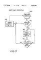
- FIG. 3 is a flow diagram relating to operation of the boiling water unit
- FIG. 4 is a flow diagram of the temperature control operation
- FIG. 5 is a flow diagram of the overload protection operation
- FIG. 6 is a flow diagram of the ⁇ After Hours ⁇ operation.
- the boiling water unit shown in FIG. 1 has an electronic temperature sensing device in the form of a thermister 50 located within the level control tank 3 at a position remote from the interconnecting conduit 21.
- the thermister 50 is sensitive to detect temperature and is connected with an electronic controller 52 by an interconnecting wire 56.
- the thermister 50 detects that the water in the heating tank 1 is boiling by sensing the temperature of the surrounding air.
- the air temperature is elevated due to the presence of steam coming-off the water and passing through the conduit 21 into the space above the water level in the level control tank 3.
- some of the steam given off travels into the level control tank 3 and raises the ambient air temperature to about 85° C.
- a thermister 54 forming a part of the over-pressure safety device situated atop the level control tank 3, replaces the capillary 29 shown in Patent No. 531449.
- FIG. 3 shows a flow diagram of the primary routine (or main loop). Within this main loop a subordinate temperature control routine, shown in FIG. 4, takes place, as does an After Hours operation routine, shown in FIG. 6.
- the overload protection routine, shown in FIG. 5, functions independently of the main loop.
- the controller 52 receives the active power wire 14, passing through two inline relay controlled contacts 60,82.
- the output signal of the thermister 50, passed along wire 56, is supplied to an input buffer device 64.
- the output signal from the thermister 54, passed by the wire 58 is supplied to the input buffer device 64.
- These two signals are converted into an appropriate data format suitable to be read by the processor 66. That data is passed from the input buffer device 64 to the processor 66 via a data bus 68.
- the processor 66 outputs signals to control each of the relay control devices 76,80.
- the relay control device 76 receives its controlling signal on output line 74, whilst the relay control device 80 receives its controlling signal by output line 78.
- Each relay control device 76,80 cause opening and closing of a respective contact 60,82.
- the contacts 60,82 control the supply or the cut-off of electricity to the heating element 2.
- FIG. 2 also shows a user control panel 90, for convenience indicated as a part of the electronic controller 52. It is equally possible that the user controls 90 are remote from the control 52, but connected thereto by an extended form of the bus arrangement 91.
- the user controls include a time of day clock that is user adjustable with respect to the time of day, and also with respect to the hours between which the After Hours operation is to take place.
- a pushbutton 92 is provided that allows selection of either continuous operation or After Hours operation.
- a ready LED 94 is provided as is an After Hours LED 96.
- the main loop commences at step 100, and firstly requires setting of a time-of-day clock (steps 101 and 102). This is followed by setting of the time-of-day pertaining to the energy saving function (steps 103 and 104), by which a time is set, typically outside of normal business hours, in which the boiling water unit is not required to continuously maintain boiling water for use.
- the energy saving mode therefore allocated a time of day where the boiling water unit automatically switches off, thus providing a significant energy saving.
- Step 105 determines whether a 24 hour mode is selected. This is a determination of whether continuous boiling water is required for 24 hours of the day. If so, then the routine continues to step 106, but if not, the energy saver operation is commenced (steps 108-112). The After Hours (energy saving) operation (step 112) is shown in more detail in FIG. 6.
- the temperature control routine (step 107) is continuously performed. Referring to FIG. 4, it can be seen that the temperature control firstly determines whether the water temperature sensed by the thermister 50 is greater than an adjustable "set temperature", corresponding to boiling of the water in the water heating tank 1.
- the "set temperature” value is variable, since the temperature of boiling will reduce with increasing altitude.
- the set level is adjusted by the supplier before delivery by means of the potentiometer 75 shown in FIG. 2.
- the element 2 is caused to turn ON (step 124). If the water temperature is greater than or equal to the "set temperature", it is not necessary to heat the water, but at the same time a three minute timer commences (step 121). If that time period has not elapsed, then the heating element 2 remains turned OFF (step 122). Therefore, in this embodiment, the thermister 50 is used only to determine when the temperature of water in the heating tank 1 is boiling. The determination of whether the water temperature has decreased to a point where it requires to be reheated is governed entirely by the timer. When the three minute interval times out the heating element 2 is caused to turn ON.
- the output signal of the thermister 50 in determining when the element is to be turned on.
- the time period of three minutes is variable, and dependents upon the normal convective heat losses from the boiling water unit. Therefore, the "set time" interval also is factory adjustable.
- the steps 124,122 that turn the heating element 2 ON and OFF therefore cause an output to be placed on the line 74, respectively to cause the relay control device 76 to close or open the contact 60, thereby either supplying or cutting-off electricity to the heating element 2.
- the After Hours operation operates such that the boiling water unit is turned OFF unless required for use.
- After Hours service step 152
- After Hours pushbutton 92 the water is heated to boiling and maintained in this condition by temperature control routine (step 159 and FIG. 3) for a period of fifteen minutes, after which time the boiling water unit is switched OFF.
- the Ready LED 94 flashes, and when the water is boiling, the LED is maintained as a steady light (steps 158,157).
- Steps 151,153 and 155 also control operation of the ready LED 94 and the After Hours LED 96.
- FIG. 5 shows the overload protection routine. This routine operates independently of the main loop shown in FIG. 3. An electrical input signal from the safety or overload thermister 54 is separately processed by the processor 66 to gain an indication of temperature, and thereby obtain a back-up system should the primary temperature sensing thermister 50 fail.
- step 141 represents a determination of the sensing of excess temperature. If this is not the case, then step 144 enables the heating element to be ON being effected by maintaining the contact 82 as closed. On the other hand, if there is an overload condition, then step 142 disables the supply of electricity to the element by opening the contact 82.
- the step 143 contemplates the situation where the overload sensing device is resettable.
- the thermister 54 can be mounted at any convenient location on the boiling water unit.
- One embodiment has the thermister 54 as a part of the over-pressure safety device 24.
- the boiling water unit is the subject of convective heat loss, in which case regular reheating of the water to boiling is required, and takes place in accordance with the methodology discussed above.
- the methodology equally applies to the instance where water is drawn-off from the outlet connection 23.
- Replenishing water is supplied to the level control tank through activation of the inlet valve 6, allowing water to discharge from the inlet pipe 7.
- the replenishing water is directed towards, and washes over, the thermister 50.
- the temperature detected by the thermister 50 then correctly determines that the water within the heating tank 1 is no longer boiling.
- This arrangement also is disclosed in commonly owned Australian Patent No. 637412.
- the thermister 50 is located in the position shown to come under the influence of the replenishing inlet water, since the ambient temperature in the level control tank 3 will, in any event, reduce.
- the After Hours function has the great benefit of saving on electrical consumption, and hence costs by, for example, shutting off the boiling water unit out of normal business hours.
- the thermister 50 can be located on the external wall surface of the level control tank 3, and the methodology for protection and control still is achievable by obtaining a knowledge of the heat loss (thermodynamic) relationship between the presence of steam within the level control tank and the surface temperature of the level control tank 3.
- An advantage in locating the thermister 50 at the external surface is that construction of the water heating unit becomes even simpler, and therefore less costly.
Landscapes
- Engineering & Computer Science (AREA)
- Food Science & Technology (AREA)
- Instantaneous Water Boilers, Portable Hot-Water Supply Apparatuses, And Control Of Portable Hot-Water Supply Apparatuses (AREA)
- Cookers (AREA)
- Heat Sensitive Colour Forming Recording (AREA)
- Control Of Temperature (AREA)
- Vaporization, Distillation, Condensation, Sublimation, And Cold Traps (AREA)
- Control Of Steam Boilers And Waste-Gas Boilers (AREA)
- Sorption Type Refrigeration Machines (AREA)
- Investigating Or Analyzing Materials Using Thermal Means (AREA)
Applications Claiming Priority (2)
| Application Number | Priority Date | Filing Date | Title |
|---|---|---|---|
| AUPM4483A AUPM448394A0 (en) | 1994-03-15 | 1994-03-15 | Protection and control of continuous boiling water units |
| AUPM4483 | 1994-03-15 |
Publications (1)
| Publication Number | Publication Date |
|---|---|
| US5692096A true US5692096A (en) | 1997-11-25 |
Family
ID=3779098
Family Applications (1)
| Application Number | Title | Priority Date | Filing Date |
|---|---|---|---|
| US08/403,336 Expired - Lifetime US5692096A (en) | 1994-03-15 | 1995-03-14 | Protection and control of continuous boiling water units |
Country Status (13)
| Country | Link |
|---|---|
| US (1) | US5692096A (de) |
| EP (1) | EP0672374B1 (de) |
| JP (1) | JP3670333B2 (de) |
| AT (1) | ATE162697T1 (de) |
| AU (1) | AUPM448394A0 (de) |
| DE (1) | DE69501508T2 (de) |
| DK (1) | DK0672374T3 (de) |
| ES (1) | ES2116040T3 (de) |
| GR (1) | GR3026605T3 (de) |
| HK (1) | HK1008725A1 (de) |
| NZ (1) | NZ270690A (de) |
| SI (1) | SI0672374T1 (de) |
| ZA (1) | ZA952112B (de) |
Cited By (16)
| Publication number | Priority date | Publication date | Assignee | Title |
|---|---|---|---|---|
| US5880438A (en) * | 1997-04-04 | 1999-03-09 | Steris Corporation | Steam sterilization apparatus and control system |
| DE29803695U1 (de) * | 1998-03-04 | 1999-07-15 | Münch GmbH, 64625 Bensheim | Vorrichtung zum Erhitzen von Trinkwasser |
| US6137955A (en) * | 1998-06-04 | 2000-10-24 | American Water Heater Company | Electric water heater with improved heating element |
| US6256456B1 (en) | 1998-02-19 | 2001-07-03 | Emerson Electric Co. | Hot water dispenser with heat dissipation plates for dry-start protection |
| US6266485B1 (en) | 1998-02-19 | 2001-07-24 | Emerson Electric Co. | One-piece plastic tank and temperature control system for a hot water dispenser |
| US6308009B1 (en) | 1998-06-04 | 2001-10-23 | American Water Heater Company | Electric water heater with electronic control |
| WO2001084060A1 (en) * | 2000-05-04 | 2001-11-08 | Emerson Electric Co. | Apparatus and method for protecting a heating tank assembly of a hot water dispenser |
| US20040040185A1 (en) * | 2001-07-27 | 2004-03-04 | Arturo Morgandi | Pressure control for household steam generator |
| DE10245825A1 (de) * | 2002-10-01 | 2004-04-22 | BSH Bosch und Siemens Hausgeräte GmbH | Vorrichtung zum Erkennen des Kochpunktes eines Kochgerätes |
| WO2004045249A1 (en) * | 2002-11-08 | 2004-05-27 | Bunn-O-Matic Corporation | Electronic thermostat for liquid heating apparatus |
| WO2005088205A1 (en) * | 2004-03-15 | 2005-09-22 | Zip Industries (Aust) Pty Ltd | A water heater and a method of operating same |
| US20090226155A1 (en) * | 2008-03-05 | 2009-09-10 | Robertshaw Controls Company | Methods for Preventing a Dry Fire Condition and a Water Heater Incorporating Same |
| CN103162404A (zh) * | 2011-12-13 | 2013-06-19 | 张海龙 | 即开式开水器石英单管发热体 |
| CN104905684A (zh) * | 2015-07-02 | 2015-09-16 | 常州华亿阳电器有限公司 | 一种能够防止高温干烧的饮水机 |
| US20170059208A1 (en) * | 2015-08-26 | 2017-03-02 | Rheem Manufacturing Company | Electric water heater having dry fire protection capability |
| US20170321927A1 (en) * | 2016-05-04 | 2017-11-09 | Lg Electronics Inc. | Induction heating module and water purifier having the same |
Families Citing this family (11)
| Publication number | Priority date | Publication date | Assignee | Title |
|---|---|---|---|---|
| GB9718246D0 (en) * | 1997-08-28 | 1997-11-05 | Strix Ltd | Electric liquid heating apparatus |
| CA2314190A1 (en) * | 1999-08-13 | 2001-02-13 | Therm-O-Disc, Incorporated | Control and method for electric water heater operation |
| KR20090031448A (ko) * | 2006-07-11 | 2009-03-25 | 코닌클리케 필립스 일렉트로닉스 엔.브이. | 물 펌핑동작을 종료할 필요가 있는 시기를 결정하는 부유부재를 구비한 음료 제조장치 |
| DE102009034322A1 (de) * | 2009-07-23 | 2011-01-27 | Wmf Württembergische Metallwarenfabrik Ag | Getränkeautomat |
| CN101900420A (zh) * | 2010-08-25 | 2010-12-01 | 章立新 | 移动式电热水器缺水保护装置 |
| CN102018447A (zh) * | 2010-08-27 | 2011-04-20 | 杨碧连 | 一种饮品快速泡制机 |
| CN102406450A (zh) * | 2011-11-25 | 2012-04-11 | 陈晓明 | 极速茶水机的面板装置 |
| CN103156518A (zh) * | 2011-12-13 | 2013-06-19 | 张海龙 | 即开式开水器 |
| CN104207648A (zh) * | 2013-05-31 | 2014-12-17 | 沁园集团股份有限公司 | 无极调温饮水机的控制方法及其系统 |
| CN104414387B (zh) * | 2013-08-28 | 2015-12-02 | 长乐市丽智产品设计有限公司 | 一种能够自动蒸发茶水的功夫茶盘 |
| CN108143287A (zh) * | 2017-12-12 | 2018-06-12 | 佛山市云米电器科技有限公司 | 一种饮水机的加热控制方法 |
Citations (11)
| Publication number | Priority date | Publication date | Assignee | Title |
|---|---|---|---|---|
| DE1250939B (de) * | 1967-09-28 | |||
| US3793934A (en) * | 1972-12-15 | 1974-02-26 | Bunn O Matic Corp | Automatic coffee maker with liquid level sensor and siphon control |
| US4354094A (en) * | 1980-11-12 | 1982-10-12 | Zip Heaters (Aust.) Pty. Limited | Thermostatically controlled electric continuous water heating unit |
| US4455477A (en) * | 1980-04-16 | 1984-06-19 | Zip Heaters (Aust) Pty. Limited | Electric boiling water heater |
| US4520259A (en) * | 1983-02-14 | 1985-05-28 | Frederick Schoenberger | Electrical energy saver |
| US4602145A (en) * | 1984-07-23 | 1986-07-22 | Bloomfield Industries, Inc. | Tap-off hot water system for electric beverage making device |
| GB2185161A (en) * | 1985-12-09 | 1987-07-08 | Otter Controls Ltd | Controls for electrical heating elements of water heaters |
| DE3733917A1 (de) * | 1987-10-07 | 1989-04-20 | Schwelm Tanksysteme Gmbh | Vorrichtung fuer die abgabe von heissem und von warmem brauchwasser |
| US5001969A (en) * | 1990-01-22 | 1991-03-26 | Proctor-Silex, Inc. | Automatic drip coffee maker |
| FR2653532A1 (fr) * | 1989-10-25 | 1991-04-26 | Bunn O Matic Corp | Ensemble capteur pour chauffe-eau a eau bouillante. |
| US5263116A (en) * | 1991-08-07 | 1993-11-16 | Heatrae Sadia Heating Limited | Heater for liquid |
Family Cites Families (3)
| Publication number | Priority date | Publication date | Assignee | Title |
|---|---|---|---|---|
| AU412689B1 (en) * | 1966-05-06 | 1971-04-23 | W. M Still & Sons Limited | IMPROVEMENTS IN OR RELATING TOTHE TEMPERATURE CONTROL OF HEATED CONTAINERS. Patent Office'Library |
| AU531449B2 (en) * | 1979-11-19 | 1983-08-25 | Zip Heaters (Australia) Pty Limited | A continuous water heating unit |
| JPH053831A (ja) * | 1991-06-28 | 1993-01-14 | Sanyo Electric Co Ltd | 自動製麺茹上げ装置 |
-
1994
- 1994-03-15 AU AUPM4483A patent/AUPM448394A0/en not_active Abandoned
-
1995
- 1995-03-13 NZ NZ270690A patent/NZ270690A/en not_active IP Right Cessation
- 1995-03-14 SI SI9530066T patent/SI0672374T1/xx unknown
- 1995-03-14 DK DK95301658T patent/DK0672374T3/da active
- 1995-03-14 EP EP95301658A patent/EP0672374B1/de not_active Expired - Lifetime
- 1995-03-14 US US08/403,336 patent/US5692096A/en not_active Expired - Lifetime
- 1995-03-14 DE DE69501508T patent/DE69501508T2/de not_active Expired - Lifetime
- 1995-03-14 ES ES95301658T patent/ES2116040T3/es not_active Expired - Lifetime
- 1995-03-14 AT AT95301658T patent/ATE162697T1/de active
- 1995-03-15 JP JP05585695A patent/JP3670333B2/ja not_active Expired - Lifetime
- 1995-03-15 ZA ZA952112A patent/ZA952112B/xx unknown
-
1998
- 1998-04-10 GR GR980400801T patent/GR3026605T3/el unknown
- 1998-07-28 HK HK98109488A patent/HK1008725A1/en not_active IP Right Cessation
Patent Citations (12)
| Publication number | Priority date | Publication date | Assignee | Title |
|---|---|---|---|---|
| DE1250939B (de) * | 1967-09-28 | |||
| US3793934A (en) * | 1972-12-15 | 1974-02-26 | Bunn O Matic Corp | Automatic coffee maker with liquid level sensor and siphon control |
| US4455477A (en) * | 1980-04-16 | 1984-06-19 | Zip Heaters (Aust) Pty. Limited | Electric boiling water heater |
| US4354094A (en) * | 1980-11-12 | 1982-10-12 | Zip Heaters (Aust.) Pty. Limited | Thermostatically controlled electric continuous water heating unit |
| US4520259A (en) * | 1983-02-14 | 1985-05-28 | Frederick Schoenberger | Electrical energy saver |
| US4602145A (en) * | 1984-07-23 | 1986-07-22 | Bloomfield Industries, Inc. | Tap-off hot water system for electric beverage making device |
| GB2185161A (en) * | 1985-12-09 | 1987-07-08 | Otter Controls Ltd | Controls for electrical heating elements of water heaters |
| DE3733917A1 (de) * | 1987-10-07 | 1989-04-20 | Schwelm Tanksysteme Gmbh | Vorrichtung fuer die abgabe von heissem und von warmem brauchwasser |
| FR2653532A1 (fr) * | 1989-10-25 | 1991-04-26 | Bunn O Matic Corp | Ensemble capteur pour chauffe-eau a eau bouillante. |
| US5038752A (en) * | 1989-10-25 | 1991-08-13 | Bunn-O-Matic Corporation | Boiling water dispenser having improved water temperature control system |
| US5001969A (en) * | 1990-01-22 | 1991-03-26 | Proctor-Silex, Inc. | Automatic drip coffee maker |
| US5263116A (en) * | 1991-08-07 | 1993-11-16 | Heatrae Sadia Heating Limited | Heater for liquid |
Non-Patent Citations (2)
| Title |
|---|
| Patent Abstracts of Japan, vol. 18, No. 101 (C 1168) Feb. 18, 1994 and JP A 5300831 (Toshiba Heating Appliances Co.) Nov. 16, 1993. * |
| Patent Abstracts of Japan, vol. 18, No. 101 (C-1168) Feb. 18, 1994 and JP-A-5300831 (Toshiba Heating Appliances Co.) Nov. 16, 1993. |
Cited By (26)
| Publication number | Priority date | Publication date | Assignee | Title |
|---|---|---|---|---|
| US5880438A (en) * | 1997-04-04 | 1999-03-09 | Steris Corporation | Steam sterilization apparatus and control system |
| US6516141B1 (en) | 1998-02-19 | 2003-02-04 | Emerson Electric Co. | Apparatus and method for protecting a heating tank assembly of a hot water dispenser |
| US6256456B1 (en) | 1998-02-19 | 2001-07-03 | Emerson Electric Co. | Hot water dispenser with heat dissipation plates for dry-start protection |
| US6266485B1 (en) | 1998-02-19 | 2001-07-24 | Emerson Electric Co. | One-piece plastic tank and temperature control system for a hot water dispenser |
| DE29803695U1 (de) * | 1998-03-04 | 1999-07-15 | Münch GmbH, 64625 Bensheim | Vorrichtung zum Erhitzen von Trinkwasser |
| US6137955A (en) * | 1998-06-04 | 2000-10-24 | American Water Heater Company | Electric water heater with improved heating element |
| US6308009B1 (en) | 1998-06-04 | 2001-10-23 | American Water Heater Company | Electric water heater with electronic control |
| WO2001084060A1 (en) * | 2000-05-04 | 2001-11-08 | Emerson Electric Co. | Apparatus and method for protecting a heating tank assembly of a hot water dispenser |
| US20040040185A1 (en) * | 2001-07-27 | 2004-03-04 | Arturo Morgandi | Pressure control for household steam generator |
| US6786182B2 (en) * | 2001-07-27 | 2004-09-07 | Imetec, S.P.A. | Pressure control for household steam generator |
| DE10245825A1 (de) * | 2002-10-01 | 2004-04-22 | BSH Bosch und Siemens Hausgeräte GmbH | Vorrichtung zum Erkennen des Kochpunktes eines Kochgerätes |
| WO2004045249A1 (en) * | 2002-11-08 | 2004-05-27 | Bunn-O-Matic Corporation | Electronic thermostat for liquid heating apparatus |
| US7263283B2 (en) | 2002-11-08 | 2007-08-28 | Bunn-O-Matic Corporation | Electronic thermostat for liquid heating apparatus |
| US20050271372A1 (en) * | 2002-11-08 | 2005-12-08 | Knepler John T | Electronic thermostat for liquid heating apparatus |
| WO2005088205A1 (en) * | 2004-03-15 | 2005-09-22 | Zip Industries (Aust) Pty Ltd | A water heater and a method of operating same |
| US20080257281A1 (en) * | 2004-03-15 | 2008-10-23 | Zip Industries (Aust) Pty Ltd | Water Heater and a Method of Operating Same |
| US20090226155A1 (en) * | 2008-03-05 | 2009-09-10 | Robertshaw Controls Company | Methods for Preventing a Dry Fire Condition and a Water Heater Incorporating Same |
| US8126320B2 (en) | 2008-03-05 | 2012-02-28 | Robertshaw Controls Company | Methods for preventing a dry fire condition and a water heater incorporating same |
| CN103162404A (zh) * | 2011-12-13 | 2013-06-19 | 张海龙 | 即开式开水器石英单管发热体 |
| CN104905684A (zh) * | 2015-07-02 | 2015-09-16 | 常州华亿阳电器有限公司 | 一种能够防止高温干烧的饮水机 |
| US20170059208A1 (en) * | 2015-08-26 | 2017-03-02 | Rheem Manufacturing Company | Electric water heater having dry fire protection capability |
| US10126018B2 (en) * | 2015-08-26 | 2018-11-13 | Rheem Manufacturing Company | Electric water heater having dry fire protection capability |
| US20170321927A1 (en) * | 2016-05-04 | 2017-11-09 | Lg Electronics Inc. | Induction heating module and water purifier having the same |
| US10267535B2 (en) * | 2016-05-04 | 2019-04-23 | Lg Electronics Inc. | Induction heating module and water purifier having the same |
| US20190170395A1 (en) * | 2016-05-04 | 2019-06-06 | Lg Electronics Inc. | Induction heating module and water purifier having the same |
| US10830493B2 (en) * | 2016-05-04 | 2020-11-10 | Lg Electronics Inc. | Induction heating module and water purifier having the same |
Also Published As
| Publication number | Publication date |
|---|---|
| DE69501508T2 (de) | 1998-08-27 |
| ZA952112B (en) | 1995-12-11 |
| DE69501508D1 (de) | 1998-03-05 |
| AUPM448394A0 (en) | 1994-04-14 |
| EP0672374A1 (de) | 1995-09-20 |
| HK1008725A1 (en) | 1999-05-14 |
| JPH0838801A (ja) | 1996-02-13 |
| JP3670333B2 (ja) | 2005-07-13 |
| GR3026605T3 (en) | 1998-07-31 |
| ATE162697T1 (de) | 1998-02-15 |
| EP0672374B1 (de) | 1998-01-28 |
| ES2116040T3 (es) | 1998-07-01 |
| SI0672374T1 (en) | 1998-08-31 |
| DK0672374T3 (da) | 1998-09-21 |
| NZ270690A (en) | 1997-02-24 |
Similar Documents
| Publication | Publication Date | Title |
|---|---|---|
| US5692096A (en) | Protection and control of continuous boiling water units | |
| HK1008725B (en) | Protection and control of continuous boiling water units | |
| AU667746B2 (en) | Electronic temperature controller for water heaters | |
| CA2633200C (en) | Programmable thermostat with preemptive setpoint adaptation based upon detection of occupancy | |
| US20240183580A1 (en) | Electronic Control System for Electric Water Heater | |
| JPS59116820A (ja) | 最適起動/停止制御装置および起動制御方法 | |
| JP2780069B2 (ja) | ユニットベンチレータのカスケード式制御方法及び装置 | |
| US5263116A (en) | Heater for liquid | |
| JP5364243B2 (ja) | 給湯装置 | |
| AU679832B2 (en) | Protection and control of continuous boiling water units | |
| GB2382646A (en) | Water heating apparatus with temperature control | |
| EP0757308B1 (de) | Schutz-Thermostat | |
| GB2368896A (en) | Heat exchange system, temperature sensor arrangement and operation | |
| US5443206A (en) | Standby loss minimizing controller for boilers with tankless water heaters | |
| KR100551194B1 (ko) | 보일러의 정전보상 이상감지 제어시스템 | |
| JPH01179804A (ja) | 二連水位制御システムにおける給水制御装置 | |
| JPH0259383B2 (de) | ||
| JP2507239B2 (ja) | 給湯器 | |
| GB2230623A (en) | Fuel rate control for heating appliance | |
| KR0134870B1 (ko) | 팬히터의 잔유량 연소시간 표시방법 | |
| JP2834262B2 (ja) | 集中制御型貯湯式電気温水器及びその制御方法 | |
| GB2230621A (en) | Controlling water heating | |
| JPH0411776B2 (de) | ||
| JPS61110840A (ja) | 電気温水器の制御装置 | |
| JPS6030936A (ja) | 貯湯式電気温水器の制御装置 |
Legal Events
| Date | Code | Title | Description |
|---|---|---|---|
| AS | Assignment |
Owner name: ZIP HEATERS (AUSTRALIA) PTY LIMITED, AUSTRALIA Free format text: ASSIGNMENT OF ASSIGNORS INTEREST;ASSIGNORS:MASSEY, RICHARD DENNIS;MASSEY, DAVID MCLEOD;SLIWA, WIESLAW HENRYK;AND OTHERS;REEL/FRAME:007584/0951 Effective date: 19950522 |
|
| STCF | Information on status: patent grant |
Free format text: PATENTED CASE |
|
| FPAY | Fee payment |
Year of fee payment: 4 |
|
| FPAY | Fee payment |
Year of fee payment: 8 |
|
| FPAY | Fee payment |
Year of fee payment: 12 |