US5693990A - Vibration isolating apparatus and vibration isolating table - Google Patents
Vibration isolating apparatus and vibration isolating table Download PDFInfo
- Publication number
- US5693990A US5693990A US08/523,137 US52313795A US5693990A US 5693990 A US5693990 A US 5693990A US 52313795 A US52313795 A US 52313795A US 5693990 A US5693990 A US 5693990A
- Authority
- US
- United States
- Prior art keywords
- vibration
- vibration isolating
- magnetic
- magnetic substance
- conducting means
- Prior art date
- Legal status (The legal status is an assumption and is not a legal conclusion. Google has not performed a legal analysis and makes no representation as to the accuracy of the status listed.)
- Expired - Fee Related
Links
Images




Classifications
-
- F—MECHANICAL ENGINEERING; LIGHTING; HEATING; WEAPONS; BLASTING
- F16—ENGINEERING ELEMENTS AND UNITS; GENERAL MEASURES FOR PRODUCING AND MAINTAINING EFFECTIVE FUNCTIONING OF MACHINES OR INSTALLATIONS; THERMAL INSULATION IN GENERAL
- F16F—SPRINGS; SHOCK-ABSORBERS; MEANS FOR DAMPING VIBRATION
- F16F15/00—Suppression of vibrations in systems; Means or arrangements for avoiding or reducing out-of-balance forces, e.g. due to motion
- F16F15/02—Suppression of vibrations of non-rotating, e.g. reciprocating systems; Suppression of vibrations of rotating systems by use of members not moving with the rotating systems
- F16F15/03—Suppression of vibrations of non-rotating, e.g. reciprocating systems; Suppression of vibrations of rotating systems by use of members not moving with the rotating systems using magnetic or electromagnetic means
-
- H—ELECTRICITY
- H02—GENERATION; CONVERSION OR DISTRIBUTION OF ELECTRIC POWER
- H02K—DYNAMO-ELECTRIC MACHINES
- H02K41/00—Propulsion systems in which a rigid body is moved along a path due to dynamo-electric interaction between the body and a magnetic field travelling along the path
- H02K41/02—Linear motors; Sectional motors
- H02K41/035—DC motors; Unipolar motors
- H02K41/0352—Unipolar motors
- H02K41/0354—Lorentz force motors, e.g. voice coil motors
- H02K41/0356—Lorentz force motors, e.g. voice coil motors moving along a straight path
-
- H—ELECTRICITY
- H02—GENERATION; CONVERSION OR DISTRIBUTION OF ELECTRIC POWER
- H02K—DYNAMO-ELECTRIC MACHINES
- H02K2201/00—Specific aspects not provided for in the other groups of this subclass relating to the magnetic circuits
- H02K2201/18—Machines moving with multiple degrees of freedom
Definitions
- the present invention relates to a vibration isolating apparatus and a vibration isolating table for actively controlling very little vibration, and particularly to a vibration isolating apparatus which is suitable for isolating vibration of a precision optical instrument, an electron microscope, a measuring instrument, a precision balance, a precision machine tool, a vibration isolating floor or the like, and to a vibration isolating table which is suitable for use in mounting these instruments thereon.
- the body to be vibrated is equipped with a mechanism for applying force from outside, and vibration of the body to be vibrated is isolated by force being applied actively to the body to be vibrated.
- this type of electromagnetic actuator-type vibration isolating apparatus 100 has a pot-type yoke 102 with a cylindrical permanent magnet 101.
- a coil 105 wound around a bobbin 104 is disposed in a gap where magnetic flux passes through.
- the bobbin 104 is supported by the yoke 102 via a pair of metallic plates 106.
- a vibrating portion 110 mounted on an object of vibration isolation is formed integrally with a leading end of the bobbin 104.
- this vibration isolating apparatus 100 is applied to, for example, a vibration isolating table 112 or the like, on which a microscope, a precision equipment or the like, being apt to be easily affected by vibration, is mounted.
- the vibration isolating table 112 is supported by a floor 116 via vibration absorbing devices 114 or the like.
- the vibration isolating apparatus 100 is disposed on the floor 116 under the vibration isolating table 112 in a state in which an axial direction of the vibration isolating apparatus 100 is placed horizontally.
- the vibrating portion 110 is fixed to a lower portion of the vibration isolating table 112.
- the vibrating portion 110 when the vibration isolating table 112 is going to move, the vibrating portion 110 generates force in a direction of stopping movement of the vibration isolating table 112 so as to control vibration of the vibration isolating table 112.
- the vibrating portion 110 of this conventional vibration isolating apparatus 100 is supported by the pair of metallic plates 106 and moves only in a predetermined direction (in the above-described example, a horizontal direction). For this reason, there exists a drawback in that, when the floor 116 vibrates in a vertical direction, this vertical vibration is transmitted to the vibration isolating table 102 via the metallic plates 106.
- a vibration isolating apparatus comprising: magnetic force generating means having a gap which allows magnetic flux to pass through in a direction intersecting a vibration direction and is connected to one of a vibration generating portion and a vibration receiving portion; conducting means which extends in a direction perpendicular to the magnetic flux passing through the gap and in a direction perpendicular to a predetermined vibration direction of the vibration generating portion and which is disposed within the gap in a state of being separated from the magnetic force generating means by a predetermined distance, the conducting means being connected to another of the vibration generating portion and the vibration receiving portion; and controlling means which charges the conducting means with an electric current so as to allow the conducting means to generate force acting in a direction opposite to the predetermined vibration direction with respect to the magnetic force generating means.
- the magnetic force generating means is connected to one of the vibration generating portion and the vibration receiving portion, and the conducting means is connected to another of the vibration generating portion and the vibration receiving portion.
- the conducting means disposed within the gap extends in the direction perpendicular to the magnetic flux passing through the gap and in the direction perpendicular to the predetermined vibration direction of the vibration generating portion. For this reason, force acting in the direction opposite to the predetermined vibration direction can be generated in the conducting means in accordance with a direction of an electric current with which the conducting means is charged, and the magnitude of force generated in the conducting means can be changed depending on an amount of electric current thereto.
- the controlling means charges the conducting means with an electric current so as to allow the conducting means to generate force acting in a direction opposite to the predetermined vibration direction with respect to the magnetic force generating means, so that vibration of the vibration receiving portion is controlled. Further, since the conducting means and the magnetic force generating means are separated from each other, even if the vibration generating portion vibrates in any direction other than a predetermined direction, the vibration is not transmitted to the vibration receiving portion via the vibration isolating apparatus. Thus, the vibration receiving portion which is an object of vibration isolation can be prevented from vibrating in the predetermined direction, and the conducting means and the magnetic force generating means are separated from each other by a predetermined distance. Accordingly, vibration in any direction other than the predetermined direction which is generated in the vibration generating portion is not transmitted to the vibration receiving portion.
- a vibration isolating table supported by a vibration generating portion via elasticity means comprising: magnetic force generating means having a gap which allows magnetic flux to pass through in a direction intersecting a vibration direction and is connected to one of a vibration generating portion and a vibration receiving portion; conducting means which extends in a direction perpendicular to the magnetic flux passing through the gap and in a direction perpendicular to a predetermined vibration direction of the vibration generating portion and which is disposed within the gap in a state of being separated from the magnetic force generating means by a predetermined distance, the conducting means being connected to another of the vibration generating portion and the vibration receiving portion; and controlling means which charges the conducting means with an electric current so as to allow the conducting means to generate force acting in a direction opposite to the predetermined vibration direction with respect to the magnetic force generating means.
- the magnetic force generating means is connected to one of the vibration generating portion and the vibration isolating table, and the conducting means is connected to another of the vibration generating portion and the vibration isolating table.
- the conducting means disposed within the gap extends in the direction perpendicular to the magnetic flux passing through the gap and in the direction perpendicular to the predetermined vibration direction of the vibration generating portion. For this reason, force acting in the direction opposite to the predetermined vibration direction of the vibration generating portion can be generated in the conducting means in accordance with a direction of an electric current applied to the conducting means, and the magnitude of force generated in the conducting means can be changed depending on an amount of electric current thereto.
- the controlling means allows an electric current to be applied to the conducting means such that the conducting means moves with respect to the magnetic force generating means in a direction opposite to the predetermined vibration direction of the vibration generating portion by the same distance as the vibration amount, so that vibration of the vibration isolating table is controlled. Further, since the conducting means and the magnetic force generating means are separated from each other, even if the vibration generating portion vibrates in any direction other than a predetermined direction, the vibration is not transmitted to the vibration isolating table. Thus, the vibration isolating table can be prevented from vibrating in the predetermined direction, and the conducting means and the magnetic force generating means are separated from each other by a predetermined distance. Accordingly, vibration of any direction other than the predetermined direction which is generated in the vibration generating portion is not transmitted to the vibration isolating table.
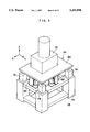
- FIG. 1 is a perspective view of a vibration isolating apparatus according to a first embodiment of the present invention
- FIG. 2 is a side view of a vibration isolating table on which the vibration isolating apparatus of the first embodiment is mounted;
- FIG. 3 is a longitudinally cross-sectional view of a vibration Isolating apparatus according to a second embodiment of the present invention.
- FIG. 4 is a plan view of a vibration isolating table according to a third embodiment of the present invention, in which rotation of the vibration isolating table can be prevented.
- FIG. 5 is a modified example of a yoke
- FIG. 6 is another modified example of the yoke
- FIG. 7 is still another modified example of the yoke
- FIG. 8 is a further different modified example of the yoke
- FIG. 9 is a perspective view of an electron-microscope supporting table to which a vibration isolating apparatus according to a fourth embodiment of the present invention is applied;
- FIG. 10 is a perspective view of the vibration isolating apparatus according to the fourth embodiment.
- FIG. 11 is a side view of the vibration isolating apparatus according to the fourth embodiment.
- FIG. 12 is a cross-sectional view of a conventional electromagnetic actuator.
- FIG. 13 is a side view of a vibration isolating table on which the conventional electromagnetic actuator is mounted.
- FIG. 2 there is shown a vibration isolating table 12 serving as a vibration receiving portion, to which a vibration isolating apparatus 10 according to the first embodiment is applied.
- the vibration isolating table 12 is supported by vibration isolating devices 16 which are respectively mounted onto four corners of the vibration isolating table 12 and fixed to a floor 14 serving as a vibration generating portion.
- the vibration isolating apparatus 10 is disposed under the vibration isolating table 12.
- the vibration isolating apparatus 10 is formed from a coil-mounting main body 18 and two yoke-mounting main bodies 20.
- the coil-mounting main body 18 is provided with a prism-shaped mounting block 22.
- An upper portion of the mounting block 22 is attached to a bottom surface of the vibration isolating table 12 at the center thereof by unillustrated bolts, adhesive or the like.
- Coils 24 project from side surfaces of the mounting block 22, which are respectively disposed in a direction indicated by arrow X and a direction indicated by arrow Y. These coils 24 are each wound in the shape of a rectangular frame and hardened by resins or the like. An axial direction of each of the coils 24 is disposed along a horizontal direction.
- the yoke-mounting main bodies 20 are respectively disposed above the floor 14 in the direction indicated by arrow X and the direction indicated by arrow Y from the coil-mounting main body 18.
- These yoke-mounting main bodies 20 are each provided with a yoke 26 forming a part of magnetic force generating means.
- the yoke 26 of the first embodiment is formed from three components: a first member 28, a second member 30, and a permanent magnet 32 forming other part of the magnetic force generating means.
- the members 28, 30 consist of magnetic substances, the first member 28 has a pair of parallel portions 28A disposed parallel to each other, and a base portion 28B which connects respective longitudinal one ends of these parallel portions 28A.
- the first member 28 has a substantially channel-shaped configuration.
- the second member 30 has a prism-shaped configuration and is provided to form a gap between the second member 30 and each of the pair of parallel portions 28A. Further, the permanent magnet 32 is disposed and fixed between the second member 30 and the base portion 28B of the first member 28. It should be noted that the permanent magnet 32 has an N pole on the side of the second member 30 and an S pole on the side of the first member 28.
- the base portion 28B of the yoke 26 is mounted on a bracket 34.
- the bracket 34 is fixed to the floor 14 by unillustrated bolts.
- the coil 24 is, as shown in FIG. 1, inserted in the gap of the yoke 26 in such a manner as to contact neither the first member 28 nor the second member 30. Further, the size of the gap is set such that the coil 24 does not contact the yoke 26 even when the coil 24 moves in any direction within a predetermined range. It should be noted that the predetermined range referred to above is the same as an amplitude of vibration of the floor 14.
- the coil 24 is sufficiently long from side to side in comparison with the second member 30. Accordingly, even when the floor 14 and the vibration isolating table 12 move relatively in a range larger than an amplitude of vibration, there is no possibility that the coil 24 be damaged.
- an acceleration sensor 36 and an acceleration sensor 38 are mounted on the vibration isolating table 12.
- the acceleration sensor 36 forms a part of controlling means for detecting a vibration amount in the direction of arrow X and a direction opposite thereto.
- the acceleration sensor 38 forms a different part of controlling means for detecting a vibration amount in the direction of arrow Y and a direction opposite thereto.
- acceleration sensors 36 and 38 are both connected to a controlling device 40 forming a further different part of the controlling means.
- the coils 24 are connected to the controlling device 40.
- the controlling device 40 controls an electric current charged for the coil 24 projecting from the coil-mounting main body 18 in the direction of arrow Y such that vibration acting on the vibration isolating table 12 in the direction of arrow X and a direction opposite thereto becomes zero. Further, when an acceleration detecting signal from the acceleration sensor 38 is inputted to the controlling device 40, the controlling device 40 controls an electric current charged for the coil 24 projecting from the coil-mounting main body 18 in the direction of arrow X such that vibration acting on the vibration isolating table 12 in the direction of arrow Y and a direction opposite thereto becomes zero.
- the controlling device 40 calculates values of vibration amount in accordance with values of the respective acceleration detecting signals from the acceleration sensors 36, 38, and then calculates current values for nullifying the calculated value of vibration amount, thereby allowing both of coils 24 to be charged with an electric current of the calculated current value.
- a hardware circuit may be used, and a software with a table or an operating equation using a CPU, ROM, RAM or the like may also be used.
- the vibration isolating table 12 In operation, for example, when the floor 14 is slightly shifted in the direction of arrow Y due to vibration, the vibration isolating table 12 is also going to move in the direction of arrow Y.
- an acceleration of the vibration isolating table 12 is detected by the acceleration sensor 38.
- the controlling device 40 receives the acceleration detecting signal from the acceleration sensor 38, the controlling device 40 allows an electric current to be applied to the coil 24 projecting from the coil-mounting main body 18 in the direction of arrow X such that the acceleration becomes zero.
- the coil 24 to which an electric current is applied receives force of the direction opposite to that of arrow Y with respect to the yoke-mounting main body 20.
- the force is transmitted to the vibration isolating table 12, which in turn moves in the direction opposite to that of arrow Y.
- the vibration of the vibration isolating apparatus 12 in the direction of arrow Y is prevented.
- the vibration of the vibration isolating table 12 can be prevented in a manner similar to the aforementioned. Accordingly, even if the floor 14 slightly vibrates in any horizontal direction, the vibration isolating table 12 does not move in the horizontal direction.
- the coil 24 and the yoke 26 do not contact each other. For this reason, for example, when the floor 14 vibrates in a vertical (Z) direction, there is no possibility that the vertical vibration of the floor 14 will be transmitted to the vibration isolating table 12 via the vibration isolating apparatus 10.
- the vertical vibration of the floor 14 is absorbed by the vibration absorbing device 16, which prevents the vibration from being transmitted to the vibration isolating table 12.
- a vibration isolating table 12 of this embodiment is adapted to control not only horizontal vibration but also vertical vibration. It should be noted that the same members as those of the first embodiment will be denoted by the same reference numerals, and a description thereof will be omitted.
- a vibration isolating apparatus 42 for control vertical vibration is disposed between the vibration isolating table 12 and the floor 14.
- the vibration isolating apparatus 42 includes a pot-type yoke 46 where a ring-shaped permanent magnet 44 is built in.
- a shaft center of the yoke 46 is disposed along a direction perpendicular to the floor 14.
- a coil 50 wound around a cylindrical bobbin 48 is inserted in a gap in such a manner as not to contact the yoke 46.
- a flange 48A is formed integrally with an upper end of the bobbin 48 and is mounted on a bottom surface of the vibration isolating table 12.
- a lower-surface outer peripheral portion of the flange 48A and an upper surface of the yoke 46 are connected with each other via a ring-shaped elastic body 52.
- the elastic body 52 is used to hold the coil 50 at a predetermined position with respect to the yoke 46.
- the elastic body 52 is made of extremely flexible rubber, sponge or the like. Meanwhile, it suffices that the elastic body 52 be softer than the vibration absorbing device 16, and various rubber materials, soft urethane material or the like can be used therefor. Accordingly, vibration of the floor 14 transmitted to the vibration isolating table 12 via the elastic body 52 can be substantially regarded as nullity.
- the coil 50 is connected to the controlling device 40 (not shown in FIG. 3), to which an acceleration sensor (not shown) is connected.
- the acceleration sensor is mounted on the vibration isolating table 12 so as to detect an acceleration of vertical vibration.
- a horizontal movement of the vibration isolating table 12 in this embodiment can be restrained by the vibration isolating apparatus 10 (not shown in FIG. 3) in the same manner as the first embodiment.
- the controlling device 40 receives an acceleration detecting signal from the acceleration sensor and controls an electric current applied to the coil 50 so as not to vibrate the vibration isolating table 12.
- the vibration isolating apparatus 42 can be controlled by the vibration isolating apparatus 42.
- the shape of the yoke 26 is not limited to those of the above-described first and second embodiments, various modifications can be applied. Modified examples of the yoke 26 will be illustrated hereinafter with reference to FIGS. 5 through 8.
- the yoke 26 shown in FIG. 5 is formed in such a manner that the second member 30 is supported by a frame-shaped magnetic substance body 60 at the center thereof via a pair of permanent magnets 32.
- the yoke 26 shown in FIG. 6 is formed in that the magnetic substance body 60 and the second member 80 are connected to be formed integrally, and the pair of permanent magnets 32 are each fixed to the magnetic substance body 60 in such a manner as to face the coil 24.
- the yoke 26 shown in FIG. 7 is formed in that prism-shaped magnetic substance bodies 64 are each held between end portions of one side of an H-shaped magnetic substance body 62 via the pair of permanent magnets 32.
- the coil 24 may be held with an extremely flexible elastic body 56 being disposed between the coil 24 and the yoke 26, as shown in FIG. 8.
- this elastic body 56 for example, rubber, sponge or the like, i.e., those having such an extent of 45 degrees at Asker hardness C, can be used.
- the vibration isolating apparatus 10 can be easily mounted on the vibration isolating table 12 or the like with the coil 24 being held at a predetermined position.
- the elastic body 56 is extremely flexible, even when the vibration isolating apparatus 10 having the elastic body 56 is applied to the vibration isolating table 12, transmittance of vibration from the floor 14 to the vibration isolating table 12 is restrained so as to be substantially regarded as nullity.
- a vibration isolating table 12 of this embodiment is formed in such a manner as to control vibration in a rotational direction of the vibration isolating table 12, i.e., in the direction indicated by arrow R. It should be noted that the same members as those of the first embodiment will be denoted by the same reference numerals, and a description thereof will be omitted.
- the vibration isolating table 12 of this embodiment is provided with two vibration isolating apparatuses 10 disposed along a diagonal line of the vibration isolating table 12. Further, the acceleration sensor 36 and the acceleration sensor 38 are formed in pairs and two sets of the acceleration sensors 36, 38 are respectively provided along the diagonal line.
- vibration of the vibration isolating table 12 in the rotational direction is detected by the two sets of the acceleration sensors 36, 38 provided along the diagonal line and two vibration isolating apparatuses 10 on the diagonal line are respectively controlled, which makes it possible to control vibration of the vibration isolating table 12 in the rotational direction thereof.
- FIGS. 9 through 11 A fourth embodiment of the present invention is described hereinafter with reference to FIGS. 9 through 11. It should be noted that the same members as those of the first embodiment will be denoted by the same reference numerals, and a description thereof will be omitted.
- a microscope table 74 serving as a vibration isolating table on which an electron microscope 72 is mounted is disposed on the floor 14.
- the microscope table 74 includes a supporting base 76 made of a high rigid member such as steel material or the like.
- An air spring 78 is mounted on each of four corners of an upper surface of the supporting base 76.
- a rectangular plate material 80 made of a high rigid material is mounted on and fixed to upper portions of these air springs 78. Meanwhile, each of the air springs 78 is formed with a spring constant thereof in the vertical direction being set small. Accordingly, the vertical vibration of the floor 14 can be shut off.
- Vibration isolating apparatuses 82 are provided on an upper surface of the supporting base 76 between each two of the air springs 78.
- the vibration isolating apparatus 82 of this embodiment has substantially the same structure as the vibration isolating apparatus 10 of the first embodiment. However, as shown in FIGS. 10 and 11, this embodiment is constructed in that a longitudinal direction of the coil 84 is different from that of the coil 24 of the first embodiment by 90 degrees and is disposed along the vertical direction. As a result, a direction of the yoke 86 is also different from that of the yoke 26 of the first embodiment by 90 degrees.
- the vibration isolating apparatus 82 for preventing vibrations in the direction indicated by arrow X and a direction opposite thereto is disposed to face in a direction in which the plate material 80 is moved in the direction of arrow X and the direction opposite thereto.
- the vibration isolating apparatus 82 disposed along the direction indicated by arrow Y and the vibration isolating apparatus 82 along a direction opposite to that of arrow Y (not shown) are respectively disposed to face in directions in which the plate material 80 is moved in the direction of arrow Y and the direction opposite thereto.
- the electron microscope 72 is mounted on and fixed to the plate material 80.
- the coil 84 can move very easily in the vertical direction. For this reason, when the plate material 80 supported by the air springs 78 each having a low spring constant is moved in the vertical direction by operating the electron microscope 72, the coil 84 and the yoke 86 can be prevented from contacting each other.
- vibration of the plate material 80 in the horizontal direction is controlled by the vibration isolating apparatuses 82 in the same manner as the first embodiment.
Landscapes
- Engineering & Computer Science (AREA)
- Physics & Mathematics (AREA)
- Electromagnetism (AREA)
- General Engineering & Computer Science (AREA)
- Chemical & Material Sciences (AREA)
- Combustion & Propulsion (AREA)
- Power Engineering (AREA)
- Acoustics & Sound (AREA)
- Aviation & Aerospace Engineering (AREA)
- Mechanical Engineering (AREA)
- Vibration Prevention Devices (AREA)
Applications Claiming Priority (2)
| Application Number | Priority Date | Filing Date | Title |
|---|---|---|---|
| JP6-212647 | 1994-09-06 | ||
| JP21264794A JPH0874928A (ja) | 1994-07-08 | 1994-09-06 | 制振装置及び除振台 |
Publications (1)
| Publication Number | Publication Date |
|---|---|
| US5693990A true US5693990A (en) | 1997-12-02 |
Family
ID=16626099
Family Applications (1)
| Application Number | Title | Priority Date | Filing Date |
|---|---|---|---|
| US08/523,137 Expired - Fee Related US5693990A (en) | 1994-09-06 | 1995-09-05 | Vibration isolating apparatus and vibration isolating table |
Country Status (3)
| Country | Link |
|---|---|
| US (1) | US5693990A (fr) |
| EP (1) | EP0701314B1 (fr) |
| DE (1) | DE69526164T2 (fr) |
Cited By (20)
| Publication number | Priority date | Publication date | Assignee | Title |
|---|---|---|---|---|
| US5975510A (en) * | 1996-06-06 | 1999-11-02 | Bridgestone Corporation | Damping apparatus |
| US6064129A (en) * | 1998-07-30 | 2000-05-16 | Hutchinson | Electromagnetic motor and active vibration-controlling apparatus including at least one such motor |
| US6089525A (en) * | 1997-10-07 | 2000-07-18 | Ultratech Stepper, Inc. | Six axis active vibration isolation and payload reaction force compensation system |
| US6202492B1 (en) * | 1996-04-05 | 2001-03-20 | Nikon Corporation | Anti-vibration apparatus and exposure apparatus |
| US6213442B1 (en) | 1998-10-08 | 2001-04-10 | Lord Corporation | Isolation system for isolation tables and the like |
| US6355994B1 (en) * | 1999-11-05 | 2002-03-12 | Multibeam Systems, Inc. | Precision stage |
| US6437864B1 (en) * | 1997-11-25 | 2002-08-20 | Ebara Corporation | Stage positioning device |
| US6501203B2 (en) * | 2001-06-01 | 2002-12-31 | Canadian Space Agency | Vibration control apparatus |
| US6654185B1 (en) * | 2000-11-14 | 2003-11-25 | Acute Applied Technologies Inc. | Electromagnetic actuator having specific coil arrangement for improving utilization rate of magnetic circuit thereof |
| US6895870B1 (en) | 2002-11-04 | 2005-05-24 | F. Peter Bizlewicz | Apparatus and method for stacking plural electronic and electro-acoustic components |
| US20060094990A1 (en) * | 2004-10-29 | 2006-05-04 | Kim Seong B | Vibratory apparatus of exercise |
| US20080169715A1 (en) * | 2007-01-17 | 2008-07-17 | Brookstone Purchasing, Inc. | Vibration apparatus and motor assembly therefore |
| EP2143409A1 (fr) | 2008-07-10 | 2010-01-13 | Leao Wang | Mécanisme de vibration électromagnétique |
| CN102118094A (zh) * | 2010-01-05 | 2011-07-06 | Lg伊诺特有限公司 | 音圈电动机 |
| WO2014072267A3 (fr) * | 2012-11-09 | 2015-09-17 | Zf Friedrichshafen Ag | Générateur à induction et procédé pour générer un courant électrique au moyen d'un générateur à induction |
| CN107357518A (zh) * | 2014-12-31 | 2017-11-17 | 刘远芳 | 触摸产生指令及自供电的控制器 |
| US20190259566A1 (en) * | 2016-07-20 | 2019-08-22 | Hitachi High-Technologies Corporation | Charged Particle Beam Device |
| US20200224746A1 (en) * | 2019-01-11 | 2020-07-16 | The Boeing Company | Couplings that actively stabilize vibrations |
| CN114598123A (zh) * | 2022-02-28 | 2022-06-07 | 复旦大学 | 一种基于磁阻电机的主动磁浮减振装置 |
| CN114857194A (zh) * | 2022-03-22 | 2022-08-05 | 中国人民解放军海军工程大学 | 一种电磁式负刚度装置 |
Families Citing this family (6)
| Publication number | Priority date | Publication date | Assignee | Title |
|---|---|---|---|---|
| JPH10288618A (ja) * | 1997-04-16 | 1998-10-27 | Seiko Instr Inc | 表面分析装置 |
| US6078114A (en) * | 1998-04-08 | 2000-06-20 | Universal Instruments Corporation | Method and apparatus for vibration reduction/control in a variable reluctance linear motor |
| CN100492826C (zh) * | 2001-02-27 | 2009-05-27 | Bei技术公司 | 具有比例螺丝管型特性的长行程线性音圈致动器 |
| WO2003104678A1 (fr) * | 2002-06-10 | 2003-12-18 | Canadian Space Agency | Appareil de controle des vibrations |
| CN114658783A (zh) * | 2022-03-22 | 2022-06-24 | 中国人民解放军海军工程大学 | 一种正负刚度均可调节的准零刚度刚度隔振器 |
| DE102022109175A1 (de) | 2022-04-14 | 2023-10-19 | Ilmenauer Mechatronik GmbH | Arbeitstisch und Verfahren zu dessen Ausrichtung |
Citations (9)
| Publication number | Priority date | Publication date | Assignee | Title |
|---|---|---|---|---|
| DE1267619B (de) * | 1962-08-22 | 1968-05-02 | Manuf Des Montres Universal | Torsionsoszillator fuer elektronische Uhren |
| US3529188A (en) * | 1966-09-29 | 1970-09-15 | Derritron Electronic Vibrators | Electro-magnetic vibrator suspension |
| US4161666A (en) * | 1976-10-18 | 1979-07-17 | Ransburg Corporation | Imbalance determining apparatus |
| SU1222933A1 (ru) * | 1983-05-04 | 1986-04-07 | Всесоюзный научно-исследовательский институт охраны труда и техники безопасности черной металлургии | Регулируемый электродинамический виброизол тор |
| JPS6223357A (ja) * | 1985-07-19 | 1987-01-31 | Showa Electric Wire & Cable Co Ltd | リニアモ−タx−yテ−ブル |
| US4976415A (en) * | 1988-06-06 | 1990-12-11 | Takenaka Corporation, A Japanese Corporation | Damping support structure |
| JPH0366952A (ja) * | 1989-08-02 | 1991-03-22 | Hitachi Ltd | 振動防止懸垂装置 |
| US5427362A (en) * | 1993-01-23 | 1995-06-27 | Firma Carl Freudenberg | Active vibration damper |
| US5449985A (en) * | 1992-08-26 | 1995-09-12 | Ebara Corporation | Zero-power control type vibration eliminating apparatus |
-
1995
- 1995-09-05 EP EP95113893A patent/EP0701314B1/fr not_active Expired - Lifetime
- 1995-09-05 DE DE69526164T patent/DE69526164T2/de not_active Expired - Fee Related
- 1995-09-05 US US08/523,137 patent/US5693990A/en not_active Expired - Fee Related
Patent Citations (9)
| Publication number | Priority date | Publication date | Assignee | Title |
|---|---|---|---|---|
| DE1267619B (de) * | 1962-08-22 | 1968-05-02 | Manuf Des Montres Universal | Torsionsoszillator fuer elektronische Uhren |
| US3529188A (en) * | 1966-09-29 | 1970-09-15 | Derritron Electronic Vibrators | Electro-magnetic vibrator suspension |
| US4161666A (en) * | 1976-10-18 | 1979-07-17 | Ransburg Corporation | Imbalance determining apparatus |
| SU1222933A1 (ru) * | 1983-05-04 | 1986-04-07 | Всесоюзный научно-исследовательский институт охраны труда и техники безопасности черной металлургии | Регулируемый электродинамический виброизол тор |
| JPS6223357A (ja) * | 1985-07-19 | 1987-01-31 | Showa Electric Wire & Cable Co Ltd | リニアモ−タx−yテ−ブル |
| US4976415A (en) * | 1988-06-06 | 1990-12-11 | Takenaka Corporation, A Japanese Corporation | Damping support structure |
| JPH0366952A (ja) * | 1989-08-02 | 1991-03-22 | Hitachi Ltd | 振動防止懸垂装置 |
| US5449985A (en) * | 1992-08-26 | 1995-09-12 | Ebara Corporation | Zero-power control type vibration eliminating apparatus |
| US5427362A (en) * | 1993-01-23 | 1995-06-27 | Firma Carl Freudenberg | Active vibration damper |
Non-Patent Citations (2)
| Title |
|---|
| Br u l & Kj r, PM Mini Shaker Type 4810 Instruction Manual , Jan. 1979, pp.1 7. * |
| Brul & Kj.oe butted.r, "PM Mini-Shaker Type 4810 Instruction Manual", Jan. 1979, pp.1-7. |
Cited By (34)
| Publication number | Priority date | Publication date | Assignee | Title |
|---|---|---|---|---|
| US6202492B1 (en) * | 1996-04-05 | 2001-03-20 | Nikon Corporation | Anti-vibration apparatus and exposure apparatus |
| US5975510A (en) * | 1996-06-06 | 1999-11-02 | Bridgestone Corporation | Damping apparatus |
| US6089525A (en) * | 1997-10-07 | 2000-07-18 | Ultratech Stepper, Inc. | Six axis active vibration isolation and payload reaction force compensation system |
| US6437864B1 (en) * | 1997-11-25 | 2002-08-20 | Ebara Corporation | Stage positioning device |
| US6064129A (en) * | 1998-07-30 | 2000-05-16 | Hutchinson | Electromagnetic motor and active vibration-controlling apparatus including at least one such motor |
| US6213442B1 (en) | 1998-10-08 | 2001-04-10 | Lord Corporation | Isolation system for isolation tables and the like |
| US6355994B1 (en) * | 1999-11-05 | 2002-03-12 | Multibeam Systems, Inc. | Precision stage |
| US20020127050A1 (en) * | 1999-11-05 | 2002-09-12 | Andeen Gerry B. | Platform positioning system |
| US6872958B2 (en) | 1999-11-05 | 2005-03-29 | Multibeam Systems, Inc. | Platform positioning system |
| US6654185B1 (en) * | 2000-11-14 | 2003-11-25 | Acute Applied Technologies Inc. | Electromagnetic actuator having specific coil arrangement for improving utilization rate of magnetic circuit thereof |
| US6501203B2 (en) * | 2001-06-01 | 2002-12-31 | Canadian Space Agency | Vibration control apparatus |
| US6895870B1 (en) | 2002-11-04 | 2005-05-24 | F. Peter Bizlewicz | Apparatus and method for stacking plural electronic and electro-acoustic components |
| US20060094990A1 (en) * | 2004-10-29 | 2006-05-04 | Kim Seong B | Vibratory apparatus of exercise |
| US7141029B2 (en) * | 2004-10-29 | 2006-11-28 | Seong Bae Kim | Vibratory apparatus of exercise |
| USRE44360E1 (en) | 2004-10-29 | 2013-07-09 | Seong Bae Kim | Vibratory apparatus of exercise |
| US7705500B2 (en) | 2007-01-17 | 2010-04-27 | Brookstone Purchasing, Inc. | Vibration apparatus and motor assembly therefore |
| US20080169715A1 (en) * | 2007-01-17 | 2008-07-17 | Brookstone Purchasing, Inc. | Vibration apparatus and motor assembly therefore |
| EP2143409A1 (fr) | 2008-07-10 | 2010-01-13 | Leao Wang | Mécanisme de vibration électromagnétique |
| CN102118094A (zh) * | 2010-01-05 | 2011-07-06 | Lg伊诺特有限公司 | 音圈电动机 |
| US20110163616A1 (en) * | 2010-01-05 | 2011-07-07 | Lg Innotek Co., Ltd. | Voice coil motor |
| US8456041B2 (en) * | 2010-01-05 | 2013-06-04 | Lg Innotek Co., Ltd. | Voice coil motor |
| CN105075080B (zh) * | 2012-11-09 | 2018-05-11 | Zf 腓德烈斯哈芬股份公司 | 感应发电器和在使用感应发电器时用于生成电流的方法 |
| CN105075080A (zh) * | 2012-11-09 | 2015-11-18 | Zf腓德烈斯哈芬股份公司 | 感应发电器和在使用感应发电器时用于生成电流的方法 |
| WO2014072267A3 (fr) * | 2012-11-09 | 2015-09-17 | Zf Friedrichshafen Ag | Générateur à induction et procédé pour générer un courant électrique au moyen d'un générateur à induction |
| US10079532B2 (en) | 2012-11-09 | 2018-09-18 | Zf Friedrichshafen Ag | Induction generator and method for generating an electric current using an induction generator |
| CN107357518A (zh) * | 2014-12-31 | 2017-11-17 | 刘远芳 | 触摸产生指令及自供电的控制器 |
| CN107357518B (zh) * | 2014-12-31 | 2024-02-13 | 刘远芳 | 触摸产生指令及自供电的控制器 |
| US20190259566A1 (en) * | 2016-07-20 | 2019-08-22 | Hitachi High-Technologies Corporation | Charged Particle Beam Device |
| US10622185B2 (en) * | 2016-07-20 | 2020-04-14 | Hitachi High-Technologies Corporation | Charged particle beam device |
| US20200224746A1 (en) * | 2019-01-11 | 2020-07-16 | The Boeing Company | Couplings that actively stabilize vibrations |
| US11028898B2 (en) * | 2019-01-11 | 2021-06-08 | The Boeing Company | Couplings that actively stabilize vibrations |
| CN114598123A (zh) * | 2022-02-28 | 2022-06-07 | 复旦大学 | 一种基于磁阻电机的主动磁浮减振装置 |
| CN114598123B (zh) * | 2022-02-28 | 2023-11-24 | 复旦大学 | 一种基于磁阻电机的主动磁浮减振装置 |
| CN114857194A (zh) * | 2022-03-22 | 2022-08-05 | 中国人民解放军海军工程大学 | 一种电磁式负刚度装置 |
Also Published As
| Publication number | Publication date |
|---|---|
| DE69526164T2 (de) | 2002-08-14 |
| EP0701314A3 (fr) | 1996-10-30 |
| EP0701314B1 (fr) | 2002-04-03 |
| EP0701314A2 (fr) | 1996-03-13 |
| DE69526164D1 (de) | 2002-05-08 |
Similar Documents
| Publication | Publication Date | Title |
|---|---|---|
| EP0701314B1 (fr) | Appareil d'isolation de vibrations et table isolée des vibrations | |
| US5610686A (en) | Exposure apparatus including an antivibration control system | |
| US5433422A (en) | Active vibration control through sensing and controlling forces on an intermediate body | |
| US5812420A (en) | Vibration-preventive apparatus and exposure apparatus | |
| JP2960692B2 (ja) | 振動減衰器 | |
| US4710656A (en) | Spring neutralized magnetic vibration isolator | |
| AU2011212653A1 (en) | Coriolis gyroscope having correction units and method for reducing the quadrature bias | |
| US7539404B2 (en) | Camera with vibration-proofing device that includes movable and fixed member with pin-shaped support member between them with curved surfaces | |
| US5975510A (en) | Damping apparatus | |
| KR102764192B1 (ko) | 촉각 정시 장치 | |
| JPH02203040A (ja) | 磁気式防振装置 | |
| JP2004340790A (ja) | 角速度センサおよび角速度検出装置 | |
| KR20130118810A (ko) | 위치 계측 장치, 패턴 전사 장치 및 디바이스 제조 방법 | |
| JP3282302B2 (ja) | 加振装置または振動除去装置 | |
| JPH0874928A (ja) | 制振装置及び除振台 | |
| JP2007240396A (ja) | 振動検出センサ、防振装置、及び露光装置 | |
| JP2004340792A (ja) | 角速度センサおよび角速度検出装置 | |
| JPH11141604A (ja) | 振動絶縁装置 | |
| JPH0674297A (ja) | 電磁アクチュエータ | |
| JP3042763B2 (ja) | 除振装置 | |
| EP1455987A1 (fr) | Appareil et procede de reduction des vibrations induites par un outil oscillant | |
| JPH09330875A (ja) | 除振装置及び露光装置 | |
| JP3807516B2 (ja) | 除振装置、除振方法及び露光装置 | |
| JPH0566832A (ja) | 2軸駆動アクチユエータ | |
| JP6016432B2 (ja) | 位置決め装置、露光装置、デバイス製造方法 |
Legal Events
| Date | Code | Title | Description |
|---|---|---|---|
| AS | Assignment |
Owner name: BRIDGESTONE CORPORATION, JAPAN Free format text: ASSIGNMENT OF ASSIGNORS INTEREST;ASSIGNOR:MIYAZAKI, TOSHIHIRO;REEL/FRAME:007634/0962 Effective date: 19950831 |
|
| FEPP | Fee payment procedure |
Free format text: PAYOR NUMBER ASSIGNED (ORIGINAL EVENT CODE: ASPN); ENTITY STATUS OF PATENT OWNER: LARGE ENTITY |
|
| FPAY | Fee payment |
Year of fee payment: 4 |
|
| REMI | Maintenance fee reminder mailed | ||
| LAPS | Lapse for failure to pay maintenance fees | ||
| STCH | Information on status: patent discontinuation |
Free format text: PATENT EXPIRED DUE TO NONPAYMENT OF MAINTENANCE FEES UNDER 37 CFR 1.362 |
|
| FP | Lapsed due to failure to pay maintenance fee |
Effective date: 20051202 |