US5697374A - Pulse rate monitor - Google Patents
Pulse rate monitor Download PDFInfo
- Publication number
- US5697374A US5697374A US08/355,503 US35550394A US5697374A US 5697374 A US5697374 A US 5697374A US 35550394 A US35550394 A US 35550394A US 5697374 A US5697374 A US 5697374A
- Authority
- US
- United States
- Prior art keywords
- pulse wave
- movement
- signal
- component
- pulse
- Prior art date
- Legal status (The legal status is an assumption and is not a legal conclusion. Google has not performed a legal analysis and makes no representation as to the accuracy of the status listed.)
- Expired - Lifetime
Links
Images




Classifications
-
- A—HUMAN NECESSITIES
- A61—MEDICAL OR VETERINARY SCIENCE; HYGIENE
- A61B—DIAGNOSIS; SURGERY; IDENTIFICATION
- A61B5/00—Measuring for diagnostic purposes; Identification of persons
- A61B5/72—Signal processing specially adapted for physiological signals or for diagnostic purposes
- A61B5/7203—Signal processing specially adapted for physiological signals or for diagnostic purposes for noise prevention, reduction or removal
- A61B5/7207—Signal processing specially adapted for physiological signals or for diagnostic purposes for noise prevention, reduction or removal of noise induced by motion artifacts
- A61B5/721—Signal processing specially adapted for physiological signals or for diagnostic purposes for noise prevention, reduction or removal of noise induced by motion artifacts using a separate sensor to detect motion or using motion information derived from signals other than the physiological signal to be measured
-
- A—HUMAN NECESSITIES
- A61—MEDICAL OR VETERINARY SCIENCE; HYGIENE
- A61B—DIAGNOSIS; SURGERY; IDENTIFICATION
- A61B5/00—Measuring for diagnostic purposes; Identification of persons
- A61B5/02—Detecting, measuring or recording for evaluating the cardiovascular system, e.g. pulse, heart rate, blood pressure or blood flow
- A61B5/024—Measuring pulse rate or heart rate
- A61B5/02438—Measuring pulse rate or heart rate with portable devices, e.g. worn by the patient
-
- A—HUMAN NECESSITIES
- A61—MEDICAL OR VETERINARY SCIENCE; HYGIENE
- A61B—DIAGNOSIS; SURGERY; IDENTIFICATION
- A61B5/00—Measuring for diagnostic purposes; Identification of persons
- A61B5/103—Measuring devices for testing the shape, pattern, colour, size or movement of the body or parts thereof, for diagnostic purposes
- A61B5/11—Measuring movement of the entire body or parts thereof, e.g. head or hand tremor or mobility of a limb
- A61B5/1104—Measuring movement of the entire body or parts thereof, e.g. head or hand tremor or mobility of a limb induced by stimuli or drugs
-
- A—HUMAN NECESSITIES
- A61—MEDICAL OR VETERINARY SCIENCE; HYGIENE
- A61B—DIAGNOSIS; SURGERY; IDENTIFICATION
- A61B5/00—Measuring for diagnostic purposes; Identification of persons
- A61B5/72—Signal processing specially adapted for physiological signals or for diagnostic purposes
- A61B5/7235—Details of waveform analysis
- A61B5/7253—Details of waveform analysis characterised by using transforms
-
- A—HUMAN NECESSITIES
- A61—MEDICAL OR VETERINARY SCIENCE; HYGIENE
- A61B—DIAGNOSIS; SURGERY; IDENTIFICATION
- A61B5/00—Measuring for diagnostic purposes; Identification of persons
- A61B5/68—Arrangements of detecting, measuring or recording means, e.g. sensors, in relation to patient
- A61B5/6801—Arrangements of detecting, measuring or recording means, e.g. sensors, in relation to patient specially adapted to be attached to or worn on the body surface
- A61B5/6802—Sensor mounted on worn items
- A61B5/681—Wristwatch-type devices
-
- A—HUMAN NECESSITIES
- A61—MEDICAL OR VETERINARY SCIENCE; HYGIENE
- A61B—DIAGNOSIS; SURGERY; IDENTIFICATION
- A61B5/00—Measuring for diagnostic purposes; Identification of persons
- A61B5/68—Arrangements of detecting, measuring or recording means, e.g. sensors, in relation to patient
- A61B5/6801—Arrangements of detecting, measuring or recording means, e.g. sensors, in relation to patient specially adapted to be attached to or worn on the body surface
- A61B5/6813—Specially adapted to be attached to a specific body part
- A61B5/6825—Hand
- A61B5/6826—Finger
-
- A—HUMAN NECESSITIES
- A61—MEDICAL OR VETERINARY SCIENCE; HYGIENE
- A61B—DIAGNOSIS; SURGERY; IDENTIFICATION
- A61B5/00—Measuring for diagnostic purposes; Identification of persons
- A61B5/72—Signal processing specially adapted for physiological signals or for diagnostic purposes
- A61B5/7235—Details of waveform analysis
- A61B5/7253—Details of waveform analysis characterised by using transforms
- A61B5/7257—Details of waveform analysis characterised by using transforms using Fourier transforms
Definitions
- the present invention relates to a pulse rate monitor mounted on a portion of a human or biological body.
- FIG. 11 is a functional block diagram for representing the construction of the conventional pulse wave detecting apparatus.
- the pulse wave detecting means 1101 detects the pulse wave signal, and outputs the detected pulse wave signal to the frequency analyzing means 1103.
- the action noise detecting means 1102 detects the action noise, or movement, signal and outputs the detected action noise signal to the frequency analyzing means 1103.
- the display means 1104 displays the frequency-analyzed result generated by the frequency analyzing means 1103.
- the control means 1105 controls the frequency analyzing means 1103 and the display means 1104.
- the conventional pulse rate monitor merely displays both the frequency analyzed result of the pulse wave sensor and the frequency analyzed result of the action noise sensor on the output display unit.
- the pulse wave frequency, or the pulse rate are specified by the user while observing the respective result representations.
- the signals are calculated in the same signal processing system with respect to the stationary condition and the action condition, and thus, the unnecessary signal processing unit is operated even under the stationary condition.
- a pulse rate monitor is arranged by employing pulse wave component extracting means for extracting pulse wave components from frequency analyzing results of a pulse wave sensor and an action noise sensor; and pulse rate calculating means for calculating a pulse rate based on the pulse wave components extracted from the pulse wave component extracting means. Further, the pulse rate monitor is arranged by confirming whether or not the action noise signal exists by action noise detecting means; and for changing the calculation method using a calculation changing means when no action noise signal exists during a predetermined period of time. As a result, the calculation amount can be reduced and the power consumption can be suppressed, so that the calculation time can be shortened.
- FIG. 1 is a functional block diagram for representing an example of a first embodiment of the pulse rate monitor of the present invention
- FIG. 2 is a functional block diagram for representing a second embodiment of the pulse rate monitor of the present invention
- FIG. 3 is a functional block diagram for showing a pulse rate monitor according to third embodiment of the present invention.
- FIG. 4 is a flow charge for showing an operation concept of CPU in the pulse rate monitor according to the first through third embodiments of the present invention.
- FIG. 5A shows an example of a waveform to be FFT-processed
- FIG. 5B indicates a result of the FFT-processed waveform
- FIG. 6A shows a result of the FFT-processed output signal of the pulse wave sensor
- FIG. 6B indicates a result of the FFT-processed output signal of the action noise sensor
- FIG. 6C represents such a pulse wave component obtained by subtracting the result of FIG. 6B from the result of FIG. 6A;
- FIG. 7 is a flow chart for indicating one example of the method for specifying the pulse wave component of the pulse rate monitor according to the present invention.
- FIG. 8 is a flow chart for indicating one example of the pulse rate monitor according to the present invention.
- FIG. 9 is a flow chart for indicating one example of the method for specifying the pulse wave component of the pulse rate monitor according to the present invention.
- FIG. 10 is a flow chart for indicating one example of the method for specifying the pulse wave component of the pulse rate monitor according to the present invention.
- FIG. 11 is a functional block diagram for indicating the arrangement of the conventional pulse rate monitor
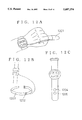
- FIGS. 12A-12C are explanatory diagrams for indicating examples of output appearance of the pulse rate monitor according to the present invention, in which FIG. 12A is an example in which the pulse rate monitor has a pulse wave sensor of the finger type, FIG. 12B is an example in which the action noise sensor is arranged into the user's belt, and FIG. 12C is an example in which the pulse wave sensor and the action noise sensor are arranged on a watch strap;
- FIG. 13 represents a result of the FFT-processed output signal from the action noise sensor.
- FIG. 14 represents an example of a functional structural diagram of a motion pitch monitor according to the present invention.
- FIG. 1 is a functional block diagram for representing a first embodiment of the pulse rate monitor according to the present invention.
- the pulse wave detecting means 101 detects a pulse wave from a human body and outputs the detected signal to the frequency analyzing means 103.
- the action noise detecting means 102 detects a movement of the human body and outputs the detected signal to the frequency analyzing means 103.
- the frequency analyzing means 103 frequency-analyzes the output signals from the pulse wave detecting means 101 and the action noise detecting means 102. To perform the frequency analysis, for instance, the Fast Fourier Transform is employed.
- the pulse wave component extracting means 104 specifies a pulse wave component corresponding to a pulse rate frequency from the frequency-analyzed results outputted from the pulse wave detecting means 101 and the action noise detecting means 102, and outputs the specified pulse wave component to the pulse rate calculating means 105.
- the pulse rate calculating means 105 calculates a pulse rate per minute from the frequency component of the pulse rate specified by the pulse wave component extracting means 104.
- the display means 106 displays the pulse rate calculated by the pulse rate calculating means 105.
- FIG. 2 is a functional block diagram representing a second embodiment of the pulse rate monitor according to the present invention.
- Pulse wave signal converting means 203 converts an analog pulse wave voltage signal of a human body, detected by the pulse wave detecting means 201, into a digital signal. The converted digital signal is outputted into pulse wave signal storing means 205.
- the action noise converting means 204 converts an analog voltage signal that is proportional to a magnitude of the action noise, detected by the action noise detecting means 202, into a digital signal.
- the converted digital signal is output into action noise signal storing means 206.
- the pulse wave signal storing means 205 stores therein the pulse wave signal converted into the digital signal.
- the action noise signal storing means 206 stores therein the action noise signal converted into the digital signal.
- Pulse wave signal calculating means 207 sequentially reads out the pulse wave signals stored in the pulse wave signal storing means 205 and frequency-analyzes the read out pulse wave signals, thereby outputting the frequency-analyzed result into pulse wave component extracting means 209.
- Action noise signal calculating means 208 sequentially reads out the action noise signals stored in the action noise signal storing means 206 and performs a frequency analysis of the read out action noise signal, thereby outputting the frequency-analyzed result into the pulse wave component extracting means 209.
- the pulse wave component extracting means 209 extracts only the pulse wave components from the frequency-analyzed results by the pulse wave signal calculating means 207 and the action noise signal calculating means 208, thereby outputting these extracted pulse wave components to calculation changing means 210.
- Timing means 211 counts a time period during which there is no action noise signal that has been rectangularized by the action noise detecting means 202, and informs when the counted time period exceeds a predetermined time period to the calculation changing means 210.
- the calculation changing means 210 Upon receipt of the "no action noise" indication issued from the timing means 211, the calculation changing means 210 outputs the pulse wave signal which has been rectangularized by the pulse wave detecting means 201 to the pulse rate calculating means 212.
- the calculation changing means 210 stops the operations of the pulse wave signal converting means 203, pulse wave signal storing means 205, pulse wave signal calculating means 207, action noise signal converting means 204, action noise signal storing means 206, action noise signal calculating means 208, and pulse wave component extracting means 209.
- calculation changing means 210 While the calculation changing means 210 outputs the rectangularized pulse wave signal to the pulse rate calculating means 212, when the action noise is detected by the action noise detecting means 202, the calculation changing means 210 immediately restarts the operations of the above described pulse wave signal converting means 203, pulse wave signal storing means 205, pulse wave signal calculating means 207, action noise signal converting means 204, action noise signal storing means 206, action noise signal calculating means 208, and pulse wave component extracting means 209, and also changes into the output signal of the pulse wave component extracting means 209.
- a pulse rate is calculated from either the frequency component of the pulse wave extracted by the pulse wave component extracting means 209, or the periodic data of the pulse wave which has been rectangularized by the pulse wave detecting means 201, and the calculation result is output to the display means 213.
- FIG. 3 is a functional block diagram for representing a pulse rate monitor according to a third embodiment of the present invention.
- a pulse wave sensor 301 senses a pulse wave from a biological body, and outputs the sensed pulse wave signal to a pulse wave signal amplifier 303.
- An action noise sensor 302 senses movement of the biological body and outputs the sensed action noise signal to an action noise signal amplifier 304.
- the pulse wave sensor for instance, a piezoelectric microphone is employed.
- an acceleration sensor is utilized.
- the pulse wave signal amplifier 303 amplifies the pulse wave signal and outputs the amplified pulse wave signal to an A/D converter 305 and a pulse wave shaper 306.
- the action noise signal amplifier 304 amplifies the action noise signal and outputs the amplified action noise signal to the A/D converter 305 and an action noise signal shaper 307.
- the A/D converter 305 converts both the pulse wave signal and the action noise signal to output the A/D-converted pulse wave signal and action noise signal to a CPU 308.
- the pulse wave signal shaper 306 shapes the pulse wave signal into a rectangular wave and outputs the shaped pulse wave signal to the CPU 308.
- the action noise signal shaper 307 shapes the action noise signal into a rectangular wave and outputs the shaped action noise signal to the CPU 308.
- FIG. 4 is a flowchart representing a sequential operation in which a confirmation is made as to whether or not the action noise signal is present, the calculation method for the pulse wave signal is changed, and the pulse rate is calculated and then displayed.
- the CPU 308 confirms whether or not the action noise signal is present in response to the output signal issued from the action noise signal shaper 307, and then switches the calculation method (S402).
- the CPU 308 performs an FFT process (S405) on the A/D-converted pulse wave signal (S403) and the A/D-converted action noise signal (S404), and further extracts the pulse wave frequency components (S406).
- the pulse wave is detected (S407) and the pulse waveform is rectangular-converted (S409). During this process, another confirmation is made as to whether or not an action noise signal is present (S408). When there is still no action noise signal (S408:NO), the pulse rate is calculated directly from the rectangular wave (S410).
- the operation of the A/D converter 305 is stopped and also the operation of the multiplier 310 is stopped which is required to perform the FFT process. Furthermore, the operation required to extract the pulse wave component executed in the CPU 308 is stopped, so that total power consumption can be lowered.
- FIGS. 5A and 5B there is graphically shown the result (FIG. 5B) obtained when a signal (FIG. 5A) including a frequency component fA and a frequency component fB equal to a half of the amplitude of the frequency component fA is FFT-processed.
- the lowest frequency obtained from the FFT-processed result is determined by the inverse number of the analyzing period of time. Assuming now that the analyzing period is 16 seconds, the line spectrum resolution becomes 1/16 seconds or 62.5 ms in period. As a consequence, the signal to be analyzed is resolved into such harmonic components being equal to 16 Hz multiplied by an integer.
- the magnitudes (power) of the respective harmonic components are denoted by a height in ordinate.
- FIG. 5B there is represented the state in which the power of the frequency component fB is equal to a half of the power of the frequency component fA.
- FIGS. 6A-6C show results obtained by FFT processing the output signals of the pulse wave sensor and the action noise sensor under an action condition.
- FIG. 6A represents a pulse wave spectrum "fmg”
- FIG. 6B indicates an action noise spectrum "fsg”
- FIG. 6C denotes a spectrum obtained by subtracting the action noise spectrum from the pulse wave spectrum, i.e., extracted pulse wave components "fM”.
- FIG. 6A both of the frequency components of the pulse waveform and the frequency components of the signal produced by the action are superimposed.
- the action noise sensor since the action noise sensor responds only to the action of the biological body, frequency components of the signal produced only by the action are obtained.
- the spectrum fsg is subtracted from the spectrum fmg, so that among the remaining line spectrum components, the maximum power component is specified as the pulse wave frequency component.
- the pulse rate is calculated (FIG. 4, S410) and the calculated pulse rate is outputted to a display element such as an LCD panel (S411).
- the maximum power frequency component among the derived pulse wave components fM is then determined (S704).
- the specified fMmax is the frequency component of the pulse wave.
- FIG. 8 there is shown a processing method for determining a pulse wave component after an action noise component is extracted from a signal of the action noise sensor, and the action noise component is eliminated from a frequency-analyzed result of a pulse wave signal.
- To extract the action noise component at least one harmonic order of the action noise component is specified, or identified, and then the other action noise components are calculated based upon the specified information of at least one harmonic order of the action noise.
- the second harmonic fs2 of the action noise sensor which is relatively easy to detect, is specified at steps S801, S802, and S803.
- the pulse wave component extracting means 104 finds a larger line spectrum frequency (fs) from the action noise signal FFT result at step S801. At first, the largest line spectrum frequency from the action noise signal FFT result is selected.
- fmin is such a frequency determined by the sampling rate for the A/D conversion.
- the sampling frequency is 8 Hz
- the maximum frequency at which the original waveform can be reproduced from the sampling theory is automatically determined as 4 Hz.
- the maximum line spectrum is specified as the second harmonic of the action noise component.
- the pulse wave component extracting means 104 finds the next frequency (fs) at step S801 and again determines whether it is within the range from fmin to fmax at step S802.
- the frequency found at step S802 is defined as the second harmonic of the action noise component at step S803.
- the pulse wave component extracting means 104 finds the second harmonic of the action noise component through steps S801 and S803.
- the fundamental harmonic fsl of the action noise component is obtained.
- the fundamental harmonic fsl of the action noise component is calculated by dividing the second harmonic of the action noise component by two at step S804.
- pulse wave components coincident with the fundamental harmonic (fsl), the second harmonic (2 ⁇ fsl), and the third harmonic (3 ⁇ fsl) of the action noise component are eliminated, and the maximum frequency component among the remaining components is specified as a pulse wave "fm" at a step S809.
- the action noise frequency is 1 to 2 Hz.
- the pulse wave component extracting means 104 finds a larger line spectrum frequency (fm) from the pulse wave signal FFT result at step S805.
- the pulse wave component extracting means 104 sets the frequency fm as the fundamental harmonic fsl of the action noise component and then finds the next frequency fm at step S805.
- the pulse wave component extracting means 104 determines that the frequency fm is not the fundamental harmonic fsl of the action noise component and then goes to step S807.
- the pulse wave component extracting means 104 determines the frequency as the second harmonic of the action noise component and then finds the next frequency fm at step S805.
- the pulse wave component extracting means 104 determines that the frequency fm is not the second harmonic of the action noise component and then goes to step S808.
- the third harmonic frequency is calculated by multiplying the fundamental frequency of the action noise signal by three.
- the pulse wave component extracting means 104 determines that the frequency fm is the third harmonic of the action noise component and then finds the next frequency fm at step S805.
- the pulse wave component extracting means 104 determines that the frequency fm is not the third harmonic of the action noise component and then goes to step S809.
- the frequency determined at step S808 is defined as the fundamental harmonic of the pulse wave component at step S809.
- FIG. 13 schematically represents results obtained by FFT-processing the outputs of the action noise sensor.
- action condition especially, under running condition, as illustrated in FIG. 13, higher power is observed in the second harmonic, as compared with that of the fundamental harmonic (i.e., 3 to 10 times higher than the fundamental harmonic during normal running).
- fundamental harmonic i.e., 3 to 10 times higher than the fundamental harmonic during normal running.
- the precision of detection may be increased by extracting the second harmonic component with the featured portion while limited to this frequency range.
- FIG. 9 there is shown a process for specifying a pulse wave component after a harmonic order of an action noise signal has been determined, or specified.
- a line spectrum fs in which power "P" is maximum is obtained from the frequency analyzed result of the action noise signal.
- Th a check is made as to whether or not an action noise component having a power higher than a predetermined value Th exists at a frequency equal to a half of fs (S902).
- the fundamental harmonic fsl of the action noise signal is obtained at a step S907.
- a fundamental harmonic of action noise component (fsl) is calculated by dividing the line spectrum fs obtained at step S901 in to the harmonic order (HMC) specified at one of steps S903, S905 and S906. Then, at a step S908, the frequency components fm are successively compared with the action noise frequency in the order of the line spectrum with the higher power P from the frequency-analyzing results of the pulse waves.
- step S908 A check is done as to whether or not this frequency component is coincident with the fundamental harmonic (fsl) of the action noise signal, the second harmonic (2 ⁇ fsl), and the third harmonic (3 ⁇ fsl) (steps S908, S909, S910, and S911).
- the maximum pulse wave frequency component fm which is not coincident with the action noise components can be extracted at a step S912.
- the frequency arrived at in step S911 is defined as the fundamental harmonic of the pulse wave component at step S912.
- FIG. 10 is a flow chart for representing a sequential operation in which a confirmation is made as to whether or not there is an action noise signal; when such a condition that the action noise signal is not confirmed exceeds a predetermined time "T", a calculation method is changed; and then a pulse rate is calculated based on a rectangular-shaped signal of pulse wave, and displayed.
- the CPU 308 makes a confirmation as to whether or not the action noise signal is present based on the output signal derived from the action noise signal shaper 307 (S1002). While the action noise signal is being confirmed (S1002:YES), a change over signal is set to OFF (S1003) so that accumulation time "Rt" for no action noise signal is set to zero (S1004).
- both the A/D converted action noise signal and pulse wave signal are FFT-processed to extract a pulse wave (S1007).
- a pulse rate is calculated (S1012) to be outputted to a display device 313 (S1013).
- the time counting operation is commenced based on the output signal derived from an oscillator 311 and a frequency divider 312, so that elapsed time Rt is accumulated (S1008).
- the accumulated time Rt exceeds a certain constant time T which is determined by either the sampling period of the signal used in the FFT process, or the sampling number (S1009:YES)
- the method for calculating the pulse rate is changed (S1010), the operations of the A/D conversion and the FFT process are stopped, and the pulse wave signal shaped by the pulse wave signal shaper 306 is entered to calculate the pulse rate (S1012). Then, the calculated pulse rate is outputted to the display device 313 (S1013).
- FIG. 14 there is shown a functional block diagram of an arrangement of a action pitch monitor.
- the frequency component of the action pitch is specified by action noise extracting means 1405.
- This specifying method may be readily realized by way of the methods previously described with reference to FIG. 8 and FIG. 9.
- running pitches corresponding to useful information for a runner can be correctly obtained.
- FIGS. 12A-12C are explanatory diagram for indicating an examples of outer appearance of the present invention.
- FIG. 12A indicates such a type of pulse rate monitor that the pulse wave sensor is assembled into a finger sack.
- FIG. 12B shows such a type of pulse rate monitor that an action noise sensor 1202 is assembled into a belt 1203.
- FIG. 12C indicates such a type of pulse wave monitor that both a pulse wave sensor 1204 and an action noise sensor 1205 are assembled into a wrist watchband in an integral form.
- the pulse wave component extracting means is employed which extracts the pulse wave components from the respective frequency-analyzed results of the pulse wave sensor and the action noise sensor, so that the pulse rate during motion condition can be displayed. Furthermore, according to the present invention, under no motion condition where the frequency analyzing process operation is not required, the operations of the A/D converter and the calculating circuit can be stopped during which high power is consumed. Accordingly, the power consumption can be suppressed. Also, since a constant time required to perform the frequency analysis is prepared from the stationary condition until the calculation method is switched, so that noncontradictory process operation may be carried out and thus such a correct pulse rate can be displayed.
Landscapes
- Health & Medical Sciences (AREA)
- Life Sciences & Earth Sciences (AREA)
- Engineering & Computer Science (AREA)
- Public Health (AREA)
- Molecular Biology (AREA)
- Physiology (AREA)
- Veterinary Medicine (AREA)
- Physics & Mathematics (AREA)
- General Health & Medical Sciences (AREA)
- Biophysics (AREA)
- Pathology (AREA)
- Biomedical Technology (AREA)
- Heart & Thoracic Surgery (AREA)
- Medical Informatics (AREA)
- Animal Behavior & Ethology (AREA)
- Surgery (AREA)
- Signal Processing (AREA)
- Computer Vision & Pattern Recognition (AREA)
- Artificial Intelligence (AREA)
- Psychiatry (AREA)
- Cardiology (AREA)
- Chemical & Material Sciences (AREA)
- Bioinformatics & Cheminformatics (AREA)
- Medicinal Chemistry (AREA)
- Dentistry (AREA)
- Oral & Maxillofacial Surgery (AREA)
- Measuring Pulse, Heart Rate, Blood Pressure Or Blood Flow (AREA)
Priority Applications (1)
| Application Number | Priority Date | Filing Date | Title |
|---|---|---|---|
| US08/918,201 US6129676A (en) | 1993-12-20 | 1997-08-25 | Movement rate monitor |
Applications Claiming Priority (4)
| Application Number | Priority Date | Filing Date | Title |
|---|---|---|---|
| JP32015793 | 1993-12-20 | ||
| JP5-320157 | 1993-12-20 | ||
| JP6302511A JP2816944B2 (ja) | 1993-12-20 | 1994-12-06 | 脈拍計 |
| JP6-302511 | 1994-12-06 |
Related Child Applications (1)
| Application Number | Title | Priority Date | Filing Date |
|---|---|---|---|
| US08/918,201 Division US6129676A (en) | 1993-12-20 | 1997-08-25 | Movement rate monitor |
Publications (1)
| Publication Number | Publication Date |
|---|---|
| US5697374A true US5697374A (en) | 1997-12-16 |
Family
ID=26563135
Family Applications (2)
| Application Number | Title | Priority Date | Filing Date |
|---|---|---|---|
| US08/355,503 Expired - Lifetime US5697374A (en) | 1993-12-20 | 1994-12-14 | Pulse rate monitor |
| US08/918,201 Expired - Lifetime US6129676A (en) | 1993-12-20 | 1997-08-25 | Movement rate monitor |
Family Applications After (1)
| Application Number | Title | Priority Date | Filing Date |
|---|---|---|---|
| US08/918,201 Expired - Lifetime US6129676A (en) | 1993-12-20 | 1997-08-25 | Movement rate monitor |
Country Status (4)
| Country | Link |
|---|---|
| US (2) | US5697374A (de) |
| EP (1) | EP0659384B1 (de) |
| JP (1) | JP2816944B2 (de) |
| DE (1) | DE69429905T2 (de) |
Cited By (39)
| Publication number | Priority date | Publication date | Assignee | Title |
|---|---|---|---|---|
| US5908396A (en) * | 1995-10-18 | 1999-06-01 | Seiko Epson Corporation | Pitch measurement device, electronic instrument, and pitch measurement method |
| US6023662A (en) * | 1995-10-18 | 2000-02-08 | Seiko Epson Corporation | Measurement device, portable electronic instrument, and measurement method |
| US6036653A (en) * | 1996-11-07 | 2000-03-14 | Seiko Epson Corporation | Pulsimeter |
| US6099478A (en) * | 1997-03-18 | 2000-08-08 | Seiko Epson Corporation | Pulse counter and pulse display method |
| US6361501B1 (en) * | 1997-08-26 | 2002-03-26 | Seiko Epson Corporation | Pulse wave diagnosing device |
| US20040017854A1 (en) * | 2002-07-26 | 2004-01-29 | Hansen Thomas H. | Method and circuit for stop of signals quantized using noise-shaping |
| US20040199081A1 (en) * | 1997-12-24 | 2004-10-07 | Braun Gmbh | Method and measuring device for determining blood pressure |
| US20050027174A1 (en) * | 2003-08-01 | 2005-02-03 | Dan Benardot | Methods, systems, and apparatus for monitoring within-day energy balance deviation |
| US20050075553A1 (en) * | 2003-10-07 | 2005-04-07 | Denso Corporation | Portable biological information monitor apparatus and information management apparatus |
| US20060195020A1 (en) * | 2003-08-01 | 2006-08-31 | Martin James S | Methods, systems, and apparatus for measuring a pulse rate |
| WO2007053146A1 (en) * | 2005-11-03 | 2007-05-10 | Georgia State University Research Foundation Inc. | Methods, systems and apparatus for measuring a pulse rate |
| US20070225586A1 (en) * | 2004-12-20 | 2007-09-27 | Takashi Nakamura | Organism information detecting apparatus |
| CN103876755A (zh) * | 2012-12-19 | 2014-06-25 | 卡西欧计算机株式会社 | 传感器数据抽取系统及传感器数据抽取方法 |
| CN103892816A (zh) * | 2012-12-27 | 2014-07-02 | 深圳迈瑞生物医疗电子股份有限公司 | 一种血压测量仪 |
| US8858454B2 (en) | 2004-10-15 | 2014-10-14 | Basis Science, Inc. | Motion cancellation of optical input signals for physiological pulse measurement |
| US8989830B2 (en) | 2009-02-25 | 2015-03-24 | Valencell, Inc. | Wearable light-guiding devices for physiological monitoring |
| US9044180B2 (en) | 2007-10-25 | 2015-06-02 | Valencell, Inc. | Noninvasive physiological analysis using excitation-sensor modules and related devices and methods |
| US9289175B2 (en) | 2009-02-25 | 2016-03-22 | Valencell, Inc. | Light-guiding devices and monitoring devices incorporating same |
| US9427191B2 (en) | 2011-07-25 | 2016-08-30 | Valencell, Inc. | Apparatus and methods for estimating time-state physiological parameters |
| US9538921B2 (en) | 2014-07-30 | 2017-01-10 | Valencell, Inc. | Physiological monitoring devices with adjustable signal analysis and interrogation power and monitoring methods using same |
| CN106539570A (zh) * | 2016-07-04 | 2017-03-29 | 悦享趋势科技(北京)有限责任公司 | 定位潮波的方法及装置 |
| US9750462B2 (en) | 2009-02-25 | 2017-09-05 | Valencell, Inc. | Monitoring apparatus and methods for measuring physiological and/or environmental conditions |
| US9794653B2 (en) | 2014-09-27 | 2017-10-17 | Valencell, Inc. | Methods and apparatus for improving signal quality in wearable biometric monitoring devices |
| US9801552B2 (en) | 2011-08-02 | 2017-10-31 | Valencell, Inc. | Systems and methods for variable filter adjustment by heart rate metric feedback |
| US20180000423A1 (en) * | 2015-03-19 | 2018-01-04 | Kabushiki Kaisha Toshiba | Measuring apparatus, measuring method and non-transitory computer readable medium |
| US9955884B2 (en) | 2016-02-11 | 2018-05-01 | General Electric Company | Method and system of monitoring cardiac function based on patient position |
| US10015582B2 (en) | 2014-08-06 | 2018-07-03 | Valencell, Inc. | Earbud monitoring devices |
| US10076253B2 (en) | 2013-01-28 | 2018-09-18 | Valencell, Inc. | Physiological monitoring devices having sensing elements decoupled from body motion |
| CN108685569A (zh) * | 2017-03-30 | 2018-10-23 | 瑞萨电子株式会社 | 脉搏测量设备、脉搏测量方法以及非暂态计算机可读介质 |
| US10258243B2 (en) | 2006-12-19 | 2019-04-16 | Valencell, Inc. | Apparatus, systems, and methods for measuring environmental exposure and physiological response thereto |
| US10413197B2 (en) | 2006-12-19 | 2019-09-17 | Valencell, Inc. | Apparatus, systems and methods for obtaining cleaner physiological information signals |
| US10610158B2 (en) | 2015-10-23 | 2020-04-07 | Valencell, Inc. | Physiological monitoring devices and methods that identify subject activity type |
| US10806399B2 (en) | 2016-11-22 | 2020-10-20 | General Electric Company | Method and system of measuring patient position |
| US10827979B2 (en) | 2011-01-27 | 2020-11-10 | Valencell, Inc. | Wearable monitoring device |
| US10874352B2 (en) | 2018-11-05 | 2020-12-29 | General Electric Company | Systems and methods for low power pulse oximetry |
| US10912505B2 (en) | 2018-11-05 | 2021-02-09 | General Electric Company | Systems and methods for low power pulse oximetery |
| US10945618B2 (en) | 2015-10-23 | 2021-03-16 | Valencell, Inc. | Physiological monitoring devices and methods for noise reduction in physiological signals based on subject activity type |
| US10966662B2 (en) | 2016-07-08 | 2021-04-06 | Valencell, Inc. | Motion-dependent averaging for physiological metric estimating systems and methods |
| US10993644B2 (en) | 2018-12-21 | 2021-05-04 | General Electric Company | SpO2 system and method |
Families Citing this family (47)
| Publication number | Priority date | Publication date | Assignee | Title |
|---|---|---|---|---|
| JP3605216B2 (ja) * | 1995-02-20 | 2004-12-22 | セイコーエプソン株式会社 | 脈拍計 |
| JPH08317912A (ja) * | 1995-03-23 | 1996-12-03 | Seiko Instr Inc | 脈拍計 |
| WO1997022295A1 (en) * | 1995-12-18 | 1997-06-26 | Seiko Epson Corporation | Health care device and exercise supporting device |
| US6042549A (en) * | 1996-03-22 | 2000-03-28 | Seiko Epson Corporation | Exercise intensity measuring device and exercise quantity measuring device |
| US6095984A (en) * | 1996-04-17 | 2000-08-01 | Seiko Epson Corporation | Arrhythmia detecting apparatus |
| FR2750236B1 (fr) * | 1996-06-21 | 1998-12-04 | Applic Electroniques Et De Tel | Dispositif de surveillance ambulatoire et son procede de mise en oeuvre |
| CN1203805C (zh) * | 1996-09-10 | 2005-06-01 | 精工爱普生株式会社 | 生物体状态测量装置及放松指导装置 |
| US6002952A (en) | 1997-04-14 | 1999-12-14 | Masimo Corporation | Signal processing apparatus and method |
| JP3666188B2 (ja) * | 1997-06-27 | 2005-06-29 | セイコーエプソン株式会社 | 心機能診断装置 |
| US6463311B1 (en) | 1998-12-30 | 2002-10-08 | Masimo Corporation | Plethysmograph pulse recognition processor |
| CA2405848C (en) | 2000-04-17 | 2010-11-09 | Vivometrics, Inc. | Systems and methods for ambulatory monitoring of physiological signs |
| US6430525B1 (en) | 2000-06-05 | 2002-08-06 | Masimo Corporation | Variable mode averager |
| US6623435B2 (en) * | 2000-07-03 | 2003-09-23 | Seiko Instruments Inc. | Pulse wave detecting apparatus |
| JP2002291709A (ja) * | 2001-03-30 | 2002-10-08 | Nippon Colin Co Ltd | 圧脈波検出装置 |
| US7355512B1 (en) | 2002-01-24 | 2008-04-08 | Masimo Corporation | Parallel alarm processor |
| JP3755501B2 (ja) | 2002-09-06 | 2006-03-15 | セイコーエプソン株式会社 | 脈拍計、脈拍計の制御方法、時計型情報機器、制御プログラムおよび記録媒体 |
| US6970792B1 (en) | 2002-12-04 | 2005-11-29 | Masimo Laboratories, Inc. | Systems and methods for determining blood oxygen saturation values using complex number encoding |
| JP3726832B2 (ja) | 2003-03-19 | 2005-12-14 | セイコーエプソン株式会社 | 脈拍計、腕時計型情報機器、制御プログラムおよび記録媒体 |
| JP4832289B2 (ja) * | 2003-04-10 | 2011-12-07 | アディダス アーゲー | 呼吸事象検出システムおよび方法 |
| JP4120537B2 (ja) * | 2003-09-02 | 2008-07-16 | 松下電器産業株式会社 | 生体情報検出装置 |
| WO2005023105A1 (ja) * | 2003-09-02 | 2005-03-17 | Matsushita Electric Industrial Co., Ltd. | 生体センサ及びこれを用いた支援システム |
| US7438683B2 (en) | 2004-03-04 | 2008-10-21 | Masimo Corporation | Application identification sensor |
| JP3626171B1 (ja) * | 2004-05-14 | 2005-03-02 | 株式会社オサチ | 循環動態評価装置 |
| US9492084B2 (en) | 2004-06-18 | 2016-11-15 | Adidas Ag | Systems and methods for monitoring subjects in potential physiological distress |
| WO2006018833A2 (en) * | 2004-08-16 | 2006-02-23 | Tadiran Spectralink Ltd. | A wearable device, system and method for measuring a pulse while a user is in motion |
| JP5328159B2 (ja) | 2005-03-01 | 2013-10-30 | セルカコア・ラボラトリーズ・インコーポレーテッド | 多波長センサ発光体 |
| US8260405B2 (en) * | 2005-12-19 | 2012-09-04 | Koninklijke Philips Electronics N.V. | Monitoring apparatus for monitoring a user's heart rate and/or heart rate variation; wristwatch comprising such a monitoring apparatus |
| EP1908402B1 (de) * | 2006-10-06 | 2015-12-09 | ETA SA Manufacture Horlogère Suisse | Verfahren und Vorrichtung zur Ausmessung des Herzschlags |
| EP1908401A1 (de) * | 2006-10-06 | 2008-04-09 | ETA SA Manufacture Horlogère Suisse | Verfahren und Vorrichtung zur Ausmessung des Herzschlags bei der Praxis eines rhythmischen Sports |
| WO2008055078A2 (en) | 2006-10-27 | 2008-05-08 | Vivometrics, Inc. | Identification of emotional states using physiological responses |
| JP5060186B2 (ja) | 2007-07-05 | 2012-10-31 | 株式会社東芝 | 脈波処理装置及び方法 |
| JP5369726B2 (ja) * | 2009-02-02 | 2013-12-18 | セイコーエプソン株式会社 | 拍動検出装置、および拍動検出方法 |
| EP2292141B1 (de) * | 2009-09-03 | 2015-06-17 | The Swatch Group Research and Development Ltd | Verfahren und Vorrichtung zum Pulsmessen mit Hilfe von Lichtwellen mit zwei Wellenlängen |
| JP5407768B2 (ja) * | 2009-11-04 | 2014-02-05 | セイコーエプソン株式会社 | 脈測定装置 |
| JP5552853B2 (ja) * | 2010-03-17 | 2014-07-16 | セイコーエプソン株式会社 | 生体情報測定装置、生体情報測定方法、および生体情報測定プログラム |
| JP5742369B2 (ja) * | 2011-03-29 | 2015-07-01 | セイコーエプソン株式会社 | 脈波計、および信号処理方法 |
| AU2013201556B2 (en) * | 2012-07-13 | 2014-06-05 | Gambro Lundia Ab | Filtering of pressure signals for suppression of periodic pulses |
| JP2014057622A (ja) * | 2012-09-14 | 2014-04-03 | Casio Comput Co Ltd | 波形データ処理装置、波形データ処理方法及びプログラム |
| TWI538660B (zh) | 2014-09-26 | 2016-06-21 | 原相科技股份有限公司 | 心跳偵測模組及其偵測、去噪方法 |
| US10478128B2 (en) | 2014-09-26 | 2019-11-19 | Pixart Imaging Inc. | Heart rate detection architecture |
| CN110292372B (zh) * | 2014-09-30 | 2022-03-01 | 原相科技股份有限公司 | 检测装置 |
| GB2532453B (en) * | 2014-11-19 | 2017-07-19 | Suunto Oy | Wearable sports monitoring equipment for measuring heart rate or muscular activity and relating method |
| JP6491920B2 (ja) * | 2015-03-25 | 2019-03-27 | クリムゾンテクノロジー株式会社 | 生体信号処理装置及び生体信号処理方法 |
| JP6052332B2 (ja) * | 2015-04-28 | 2016-12-27 | セイコーエプソン株式会社 | 脈波計、信号処理方法、およびプログラム |
| JP6036916B2 (ja) * | 2015-05-01 | 2016-11-30 | セイコーエプソン株式会社 | 生体情報処理装置 |
| EP3416538A1 (de) * | 2016-02-15 | 2018-12-26 | Koninklijke Philips N.V. | Vorrichtung und verfahren zum extrahieren von herzfrequenzinformationen |
| CN105962945B (zh) * | 2016-06-18 | 2019-08-23 | 广东乐心医疗电子股份有限公司 | 一种计算步频的方法与装置以及包含该装置的可穿戴设备 |
Citations (5)
| Publication number | Priority date | Publication date | Assignee | Title |
|---|---|---|---|---|
| US4260951A (en) * | 1979-01-29 | 1981-04-07 | Hughes Aircraft Company | Measurement system having pole zero cancellation |
| US4409983A (en) * | 1981-08-20 | 1983-10-18 | Albert David E | Pulse measuring device |
| WO1993016636A1 (en) * | 1992-02-28 | 1993-09-02 | Myllymaeki Matti | Wrist-held monitoring device for physical condition |
| US5381797A (en) * | 1993-03-26 | 1995-01-17 | Pak; Song C. | Pulse diagnostic device and method of measuring a pulse wave using this device |
| US5431170A (en) * | 1990-05-26 | 1995-07-11 | Mathews; Geoffrey R. | Pulse responsive device |
Family Cites Families (7)
| Publication number | Priority date | Publication date | Assignee | Title |
|---|---|---|---|---|
| DE3150925A1 (de) * | 1981-12-23 | 1983-06-30 | Honeywell B.V., Amsterdam | Anordnung zur pulsmessung mit einem photoelektrischen nutzsignalaufnehmer |
| US4911427A (en) * | 1984-03-16 | 1990-03-27 | Sharp Kabushiki Kaisha | Exercise and training machine with microcomputer-assisted training guide |
| JPH0315502U (de) * | 1989-06-28 | 1991-02-15 | ||
| DE4001574A1 (de) * | 1990-01-20 | 1991-07-25 | Walz Elektronik Gmbh | Vorrichtung zur erfassung der lebensfunktion von lebewesen |
| US5243992A (en) * | 1990-03-30 | 1993-09-14 | Colin Electronics Co., Ltd. | Pulse rate sensor system |
| JP2770694B2 (ja) * | 1993-01-13 | 1998-07-02 | 松下電器産業株式会社 | 生体情報処理装置 |
| US5494043A (en) * | 1993-05-04 | 1996-02-27 | Vital Insite, Inc. | Arterial sensor |
-
1994
- 1994-12-06 JP JP6302511A patent/JP2816944B2/ja not_active Expired - Lifetime
- 1994-12-14 US US08/355,503 patent/US5697374A/en not_active Expired - Lifetime
- 1994-12-20 EP EP94309563A patent/EP0659384B1/de not_active Expired - Lifetime
- 1994-12-20 DE DE69429905T patent/DE69429905T2/de not_active Expired - Lifetime
-
1997
- 1997-08-25 US US08/918,201 patent/US6129676A/en not_active Expired - Lifetime
Patent Citations (5)
| Publication number | Priority date | Publication date | Assignee | Title |
|---|---|---|---|---|
| US4260951A (en) * | 1979-01-29 | 1981-04-07 | Hughes Aircraft Company | Measurement system having pole zero cancellation |
| US4409983A (en) * | 1981-08-20 | 1983-10-18 | Albert David E | Pulse measuring device |
| US5431170A (en) * | 1990-05-26 | 1995-07-11 | Mathews; Geoffrey R. | Pulse responsive device |
| WO1993016636A1 (en) * | 1992-02-28 | 1993-09-02 | Myllymaeki Matti | Wrist-held monitoring device for physical condition |
| US5381797A (en) * | 1993-03-26 | 1995-01-17 | Pak; Song C. | Pulse diagnostic device and method of measuring a pulse wave using this device |
Cited By (117)
| Publication number | Priority date | Publication date | Assignee | Title |
|---|---|---|---|---|
| US5908396A (en) * | 1995-10-18 | 1999-06-01 | Seiko Epson Corporation | Pitch measurement device, electronic instrument, and pitch measurement method |
| US6023662A (en) * | 1995-10-18 | 2000-02-08 | Seiko Epson Corporation | Measurement device, portable electronic instrument, and measurement method |
| US6036653A (en) * | 1996-11-07 | 2000-03-14 | Seiko Epson Corporation | Pulsimeter |
| US6099478A (en) * | 1997-03-18 | 2000-08-08 | Seiko Epson Corporation | Pulse counter and pulse display method |
| US6361501B1 (en) * | 1997-08-26 | 2002-03-26 | Seiko Epson Corporation | Pulse wave diagnosing device |
| US20040199081A1 (en) * | 1997-12-24 | 2004-10-07 | Braun Gmbh | Method and measuring device for determining blood pressure |
| US6893402B2 (en) | 1997-12-24 | 2005-05-17 | Braun Gmbh | Method and measuring device for determining blood pressure |
| US20050215912A1 (en) * | 1997-12-24 | 2005-09-29 | Braun Gmbh | Method and measuring device for determining blood pressure |
| US7963921B1 (en) | 1997-12-24 | 2011-06-21 | Kaz Usa, Inc. | Method and measuring device for determining blood pressure |
| US7346113B2 (en) * | 2002-07-26 | 2008-03-18 | Texas Instruments Incorporated | Method and circuit for stop of signals quantized using noise-shaping |
| US20040017854A1 (en) * | 2002-07-26 | 2004-01-29 | Hansen Thomas H. | Method and circuit for stop of signals quantized using noise-shaping |
| US20050027174A1 (en) * | 2003-08-01 | 2005-02-03 | Dan Benardot | Methods, systems, and apparatus for monitoring within-day energy balance deviation |
| US20060195020A1 (en) * | 2003-08-01 | 2006-08-31 | Martin James S | Methods, systems, and apparatus for measuring a pulse rate |
| US20050075553A1 (en) * | 2003-10-07 | 2005-04-07 | Denso Corporation | Portable biological information monitor apparatus and information management apparatus |
| US7507207B2 (en) | 2003-10-07 | 2009-03-24 | Denso Corporation | Portable biological information monitor apparatus and information management apparatus |
| US8858454B2 (en) | 2004-10-15 | 2014-10-14 | Basis Science, Inc. | Motion cancellation of optical input signals for physiological pulse measurement |
| US20070225586A1 (en) * | 2004-12-20 | 2007-09-27 | Takashi Nakamura | Organism information detecting apparatus |
| US8096953B2 (en) * | 2004-12-20 | 2012-01-17 | Seiko Instruments Inc. | Organism information detecting apparatus |
| WO2007053146A1 (en) * | 2005-11-03 | 2007-05-10 | Georgia State University Research Foundation Inc. | Methods, systems and apparatus for measuring a pulse rate |
| US11000190B2 (en) | 2006-12-19 | 2021-05-11 | Valencell, Inc. | Apparatus, systems and methods for obtaining cleaner physiological information signals |
| US11324407B2 (en) | 2006-12-19 | 2022-05-10 | Valencell, Inc. | Methods and apparatus for physiological and environmental monitoring with optical and footstep sensors |
| US11083378B2 (en) | 2006-12-19 | 2021-08-10 | Valencell, Inc. | Wearable apparatus having integrated physiological and/or environmental sensors |
| US10987005B2 (en) | 2006-12-19 | 2021-04-27 | Valencell, Inc. | Systems and methods for presenting personal health information |
| US11412938B2 (en) | 2006-12-19 | 2022-08-16 | Valencell, Inc. | Physiological monitoring apparatus and networks |
| US11272849B2 (en) | 2006-12-19 | 2022-03-15 | Valencell, Inc. | Wearable apparatus |
| US11272848B2 (en) | 2006-12-19 | 2022-03-15 | Valencell, Inc. | Wearable apparatus for multiple types of physiological and/or environmental monitoring |
| US10716481B2 (en) | 2006-12-19 | 2020-07-21 | Valencell, Inc. | Apparatus, systems and methods for monitoring and evaluating cardiopulmonary functioning |
| US11295856B2 (en) | 2006-12-19 | 2022-04-05 | Valencell, Inc. | Apparatus, systems, and methods for measuring environmental exposure and physiological response thereto |
| US11109767B2 (en) | 2006-12-19 | 2021-09-07 | Valencell, Inc. | Apparatus, systems and methods for obtaining cleaner physiological information signals |
| US10595730B2 (en) | 2006-12-19 | 2020-03-24 | Valencell, Inc. | Physiological monitoring methods |
| US11350831B2 (en) | 2006-12-19 | 2022-06-07 | Valencell, Inc. | Physiological monitoring apparatus |
| US10413197B2 (en) | 2006-12-19 | 2019-09-17 | Valencell, Inc. | Apparatus, systems and methods for obtaining cleaner physiological information signals |
| US10258243B2 (en) | 2006-12-19 | 2019-04-16 | Valencell, Inc. | Apparatus, systems, and methods for measuring environmental exposure and physiological response thereto |
| US11395595B2 (en) | 2006-12-19 | 2022-07-26 | Valencell, Inc. | Apparatus, systems and methods for monitoring and evaluating cardiopulmonary functioning |
| US11399724B2 (en) | 2006-12-19 | 2022-08-02 | Valencell, Inc. | Earpiece monitor |
| US9044180B2 (en) | 2007-10-25 | 2015-06-02 | Valencell, Inc. | Noninvasive physiological analysis using excitation-sensor modules and related devices and methods |
| US9808204B2 (en) | 2007-10-25 | 2017-11-07 | Valencell, Inc. | Noninvasive physiological analysis using excitation-sensor modules and related devices and methods |
| US11589812B2 (en) | 2009-02-25 | 2023-02-28 | Valencell, Inc. | Wearable devices for physiological monitoring |
| US10842389B2 (en) | 2009-02-25 | 2020-11-24 | Valencell, Inc. | Wearable audio devices |
| US10973415B2 (en) | 2009-02-25 | 2021-04-13 | Valencell, Inc. | Form-fitted monitoring apparatus for health and environmental monitoring |
| US9955919B2 (en) | 2009-02-25 | 2018-05-01 | Valencell, Inc. | Light-guiding devices and monitoring devices incorporating same |
| US11471103B2 (en) | 2009-02-25 | 2022-10-18 | Valencell, Inc. | Ear-worn devices for physiological monitoring |
| US11660006B2 (en) | 2009-02-25 | 2023-05-30 | Valencell, Inc. | Wearable monitoring devices with passive and active filtering |
| US11026588B2 (en) | 2009-02-25 | 2021-06-08 | Valencell, Inc. | Methods and apparatus for detecting motion noise and for removing motion noise from physiological signals |
| US10076282B2 (en) | 2009-02-25 | 2018-09-18 | Valencell, Inc. | Wearable monitoring devices having sensors and light guides |
| US10898083B2 (en) | 2009-02-25 | 2021-01-26 | Valencell, Inc. | Wearable monitoring devices with passive and active filtering |
| US10092245B2 (en) | 2009-02-25 | 2018-10-09 | Valencell, Inc. | Methods and apparatus for detecting motion noise and for removing motion noise from physiological signals |
| US9750462B2 (en) | 2009-02-25 | 2017-09-05 | Valencell, Inc. | Monitoring apparatus and methods for measuring physiological and/or environmental conditions |
| US11160460B2 (en) | 2009-02-25 | 2021-11-02 | Valencell, Inc. | Physiological monitoring methods |
| US10842387B2 (en) | 2009-02-25 | 2020-11-24 | Valencell, Inc. | Apparatus for assessing physiological conditions |
| US8989830B2 (en) | 2009-02-25 | 2015-03-24 | Valencell, Inc. | Wearable light-guiding devices for physiological monitoring |
| US9131312B2 (en) | 2009-02-25 | 2015-09-08 | Valencell, Inc. | Physiological monitoring methods |
| US10448840B2 (en) | 2009-02-25 | 2019-10-22 | Valencell, Inc. | Apparatus for generating data output containing physiological and motion-related information |
| US9289175B2 (en) | 2009-02-25 | 2016-03-22 | Valencell, Inc. | Light-guiding devices and monitoring devices incorporating same |
| US10750954B2 (en) | 2009-02-25 | 2020-08-25 | Valencell, Inc. | Wearable devices with flexible optical emitters and/or optical detectors |
| US10716480B2 (en) | 2009-02-25 | 2020-07-21 | Valencell, Inc. | Hearing aid earpiece covers |
| US10542893B2 (en) | 2009-02-25 | 2020-01-28 | Valencell, Inc. | Form-fitted monitoring apparatus for health and environmental monitoring |
| US9289135B2 (en) | 2009-02-25 | 2016-03-22 | Valencell, Inc. | Physiological monitoring methods and apparatus |
| US9314167B2 (en) | 2009-02-25 | 2016-04-19 | Valencell, Inc. | Methods for generating data output containing physiological and motion-related information |
| US9301696B2 (en) | 2009-02-25 | 2016-04-05 | Valencell, Inc. | Earbud covers |
| US10827979B2 (en) | 2011-01-27 | 2020-11-10 | Valencell, Inc. | Wearable monitoring device |
| US11324445B2 (en) | 2011-01-27 | 2022-05-10 | Valencell, Inc. | Headsets with angled sensor modules |
| US9788785B2 (en) | 2011-07-25 | 2017-10-17 | Valencell, Inc. | Apparatus and methods for estimating time-state physiological parameters |
| US9427191B2 (en) | 2011-07-25 | 2016-08-30 | Valencell, Inc. | Apparatus and methods for estimating time-state physiological parameters |
| US9521962B2 (en) | 2011-07-25 | 2016-12-20 | Valencell, Inc. | Apparatus and methods for estimating time-state physiological parameters |
| US9801552B2 (en) | 2011-08-02 | 2017-10-31 | Valencell, Inc. | Systems and methods for variable filter adjustment by heart rate metric feedback |
| US11375902B2 (en) | 2011-08-02 | 2022-07-05 | Valencell, Inc. | Systems and methods for variable filter adjustment by heart rate metric feedback |
| US10512403B2 (en) | 2011-08-02 | 2019-12-24 | Valencell, Inc. | Systems and methods for variable filter adjustment by heart rate metric feedback |
| CN103876755B (zh) * | 2012-12-19 | 2016-04-20 | 卡西欧计算机株式会社 | 传感器数据抽取系统及传感器数据抽取方法 |
| CN103876755A (zh) * | 2012-12-19 | 2014-06-25 | 卡西欧计算机株式会社 | 传感器数据抽取系统及传感器数据抽取方法 |
| WO2014101466A1 (zh) * | 2012-12-27 | 2014-07-03 | 深圳迈瑞生物医疗电子股份有限公司 | 一种血压测量仪 |
| CN103892816A (zh) * | 2012-12-27 | 2014-07-02 | 深圳迈瑞生物医疗电子股份有限公司 | 一种血压测量仪 |
| CN103892816B (zh) * | 2012-12-27 | 2018-07-06 | 深圳迈瑞生物医疗电子股份有限公司 | 一种血压测量仪 |
| US11266319B2 (en) | 2013-01-28 | 2022-03-08 | Valencell, Inc. | Physiological monitoring devices having sensing elements decoupled from body motion |
| US12076126B2 (en) | 2013-01-28 | 2024-09-03 | Yukka Magic Llc | Physiological monitoring devices having sensing elements decoupled from body motion |
| US10856749B2 (en) | 2013-01-28 | 2020-12-08 | Valencell, Inc. | Physiological monitoring devices having sensing elements decoupled from body motion |
| US11684278B2 (en) | 2013-01-28 | 2023-06-27 | Yukka Magic Llc | Physiological monitoring devices having sensing elements decoupled from body motion |
| US10076253B2 (en) | 2013-01-28 | 2018-09-18 | Valencell, Inc. | Physiological monitoring devices having sensing elements decoupled from body motion |
| US11179108B2 (en) | 2014-07-30 | 2021-11-23 | Valencell, Inc. | Physiological monitoring devices and methods using optical sensors |
| US11185290B2 (en) | 2014-07-30 | 2021-11-30 | Valencell, Inc. | Physiological monitoring devices and methods using optical sensors |
| US12274567B2 (en) | 2014-07-30 | 2025-04-15 | Yukka Magic Llc | Physiological monitoring devices and methods using optical sensors |
| US12193845B2 (en) | 2014-07-30 | 2025-01-14 | Yukka Magic Llc | Physiological monitoring devices and methods using optical sensors |
| US9538921B2 (en) | 2014-07-30 | 2017-01-10 | Valencell, Inc. | Physiological monitoring devices with adjustable signal analysis and interrogation power and monitoring methods using same |
| US11638561B2 (en) | 2014-07-30 | 2023-05-02 | Yukka Magic Llc | Physiological monitoring devices with adjustable signal analysis and interrogation power and monitoring methods using same |
| US11638560B2 (en) | 2014-07-30 | 2023-05-02 | Yukka Magic Llc | Physiological monitoring devices and methods using optical sensors |
| US10893835B2 (en) | 2014-07-30 | 2021-01-19 | Valencell, Inc. | Physiological monitoring devices with adjustable signal analysis and interrogation power and monitoring methods using same |
| US11412988B2 (en) | 2014-07-30 | 2022-08-16 | Valencell, Inc. | Physiological monitoring devices and methods using optical sensors |
| US11337655B2 (en) | 2014-07-30 | 2022-05-24 | Valencell, Inc. | Physiological monitoring devices and methods using optical sensors |
| US10536768B2 (en) | 2014-08-06 | 2020-01-14 | Valencell, Inc. | Optical physiological sensor modules with reduced signal noise |
| US10015582B2 (en) | 2014-08-06 | 2018-07-03 | Valencell, Inc. | Earbud monitoring devices |
| US11252498B2 (en) | 2014-08-06 | 2022-02-15 | Valencell, Inc. | Optical physiological monitoring devices |
| US11252499B2 (en) | 2014-08-06 | 2022-02-15 | Valencell, Inc. | Optical physiological monitoring devices |
| US11330361B2 (en) | 2014-08-06 | 2022-05-10 | Valencell, Inc. | Hearing aid optical monitoring apparatus |
| US10623849B2 (en) | 2014-08-06 | 2020-04-14 | Valencell, Inc. | Optical monitoring apparatus and methods |
| US10779062B2 (en) | 2014-09-27 | 2020-09-15 | Valencell, Inc. | Wearable biometric monitoring devices and methods for determining if wearable biometric monitoring devices are being worn |
| US9794653B2 (en) | 2014-09-27 | 2017-10-17 | Valencell, Inc. | Methods and apparatus for improving signal quality in wearable biometric monitoring devices |
| US10798471B2 (en) | 2014-09-27 | 2020-10-06 | Valencell, Inc. | Methods for improving signal quality in wearable biometric monitoring devices |
| US10834483B2 (en) | 2014-09-27 | 2020-11-10 | Valencell, Inc. | Wearable biometric monitoring devices and methods for determining if wearable biometric monitoring devices are being worn |
| US10506310B2 (en) | 2014-09-27 | 2019-12-10 | Valencell, Inc. | Wearable biometric monitoring devices and methods for determining signal quality in wearable biometric monitoring devices |
| US10382839B2 (en) | 2014-09-27 | 2019-08-13 | Valencell, Inc. | Methods for improving signal quality in wearable biometric monitoring devices |
| US10980485B2 (en) | 2015-03-19 | 2021-04-20 | Kabushiki Kaisha Toshiba | Measuring apparatus, measuring method and non-transitory computer readable medium |
| US20180000423A1 (en) * | 2015-03-19 | 2018-01-04 | Kabushiki Kaisha Toshiba | Measuring apparatus, measuring method and non-transitory computer readable medium |
| US12285244B2 (en) | 2015-10-23 | 2025-04-29 | Yukka Magic Llc | Physiological monitoring devices and methods for noise reduction in physiological signals based on subject activity type |
| US10945618B2 (en) | 2015-10-23 | 2021-03-16 | Valencell, Inc. | Physiological monitoring devices and methods for noise reduction in physiological signals based on subject activity type |
| US10610158B2 (en) | 2015-10-23 | 2020-04-07 | Valencell, Inc. | Physiological monitoring devices and methods that identify subject activity type |
| US9955884B2 (en) | 2016-02-11 | 2018-05-01 | General Electric Company | Method and system of monitoring cardiac function based on patient position |
| US10194817B2 (en) | 2016-02-11 | 2019-02-05 | General Electric Company | Method and system of monitoring cardiac function based on patient position |
| CN106539570A (zh) * | 2016-07-04 | 2017-03-29 | 悦享趋势科技(北京)有限责任公司 | 定位潮波的方法及装置 |
| US10966662B2 (en) | 2016-07-08 | 2021-04-06 | Valencell, Inc. | Motion-dependent averaging for physiological metric estimating systems and methods |
| US10806399B2 (en) | 2016-11-22 | 2020-10-20 | General Electric Company | Method and system of measuring patient position |
| CN108685569A (zh) * | 2017-03-30 | 2018-10-23 | 瑞萨电子株式会社 | 脉搏测量设备、脉搏测量方法以及非暂态计算机可读介质 |
| US11058360B2 (en) | 2017-03-30 | 2021-07-13 | Renesas Electronics Corporation | Pulse measurement device, pulse measurement method and non-transitory computer readable medium |
| US10874352B2 (en) | 2018-11-05 | 2020-12-29 | General Electric Company | Systems and methods for low power pulse oximetry |
| US10912505B2 (en) | 2018-11-05 | 2021-02-09 | General Electric Company | Systems and methods for low power pulse oximetery |
| US11564630B2 (en) | 2018-11-05 | 2023-01-31 | GE Precision Healthcare LLC | Systems and methods for low power pulse oximetry |
| US11540755B2 (en) | 2018-11-05 | 2023-01-03 | GE Precision Healthcare LLC | Systems and methods for low power pulse oximetry |
| US10993644B2 (en) | 2018-12-21 | 2021-05-04 | General Electric Company | SpO2 system and method |
Also Published As
| Publication number | Publication date |
|---|---|
| JP2816944B2 (ja) | 1998-10-27 |
| US6129676A (en) | 2000-10-10 |
| EP0659384A1 (de) | 1995-06-28 |
| JPH07227383A (ja) | 1995-08-29 |
| EP0659384B1 (de) | 2002-02-20 |
| DE69429905T2 (de) | 2002-08-14 |
| DE69429905D1 (de) | 2002-03-28 |
Similar Documents
| Publication | Publication Date | Title |
|---|---|---|
| US5697374A (en) | Pulse rate monitor | |
| EP2065680B1 (de) | Vorrichtung zur Erfassung von Körperbewegungen | |
| US6036653A (en) | Pulsimeter | |
| JP5369726B2 (ja) | 拍動検出装置、および拍動検出方法 | |
| WO1998041142A1 (en) | Pulsometer and pulsation indication method | |
| JPH10258038A (ja) | 脈波検出装置および脈拍計 | |
| WO2008029587A1 (fr) | Dispositif de mesure médicale destiné à la production d'informations utiles pour un diagnostic | |
| JP2000166877A5 (de) | ||
| US5253650A (en) | Apparatus for recording an electrocardiogram | |
| JP3236710B2 (ja) | 実効値等の測定装置 | |
| JP3815663B2 (ja) | 脈に関する情報を検出可能な測定装置 | |
| JPS624971B2 (de) | ||
| JP3288156B2 (ja) | 脈拍計 | |
| JP4606236B2 (ja) | 重量測定方法 | |
| KR970062706A (ko) | 단시간 지속되는 아날로그 신호 이벤트의 획득 및 표시를 위한 전자신호 측정장치 | |
| JP2601799B2 (ja) | 軸受破壊予知方法 | |
| JP2011080911A (ja) | 周波数測定装置及び同周波数測定装置を備えた電子機器 | |
| JP4455938B2 (ja) | 電圧測定装置 | |
| JP3498379B2 (ja) | 心拍計 | |
| JPH0274859A (ja) | 振動試験装置 | |
| KR0137409B1 (ko) | 텔레비젼을 이용한 맥박측정 방법 및 그 장치 | |
| JP2501814Y2 (ja) | アナログ信号入力装置 | |
| JPH01228060A (ja) | Fft演算装置 | |
| JPH021566A (ja) | 周期測定装置 | |
| SU1650091A1 (ru) | Устройство дл исследовани биомеханических процессов |
Legal Events
| Date | Code | Title | Description |
|---|---|---|---|
| AS | Assignment |
Owner name: SEIKO INSTRUMENTS INC., JAPAN Free format text: ASSIGNMENT OF ASSIGNORS INTEREST;ASSIGNORS:ODAGIRI, HIROSHI;TSUBATA, KEISUKE;NAKAMURA, CHIAKI;AND OTHERS;REEL/FRAME:008619/0632 Effective date: 19970708 |
|
| STCF | Information on status: patent grant |
Free format text: PATENTED CASE |
|
| FPAY | Fee payment |
Year of fee payment: 4 |
|
| FPAY | Fee payment |
Year of fee payment: 8 |
|
| FPAY | Fee payment |
Year of fee payment: 12 |