US5771997A - Braking system in conjunction with a hydrodynamic retarder, specifically for motor vehicles - Google Patents
Braking system in conjunction with a hydrodynamic retarder, specifically for motor vehicles Download PDFInfo
- Publication number
- US5771997A US5771997A US08/562,962 US56296295A US5771997A US 5771997 A US5771997 A US 5771997A US 56296295 A US56296295 A US 56296295A US 5771997 A US5771997 A US 5771997A
- Authority
- US
- United States
- Prior art keywords
- retarder
- sump
- braking system
- working space
- valve
- Prior art date
- Legal status (The legal status is an assumption and is not a legal conclusion. Google has not performed a legal analysis and makes no representation as to the accuracy of the status listed.)
- Expired - Fee Related
Links
- 238000013022 venting Methods 0.000 claims abstract description 5
- 239000012530 fluid Substances 0.000 claims 7
- 238000001816 cooling Methods 0.000 description 3
- 239000000203 mixture Substances 0.000 description 3
- 230000000694 effects Effects 0.000 description 2
- 238000005192 partition Methods 0.000 description 2
- 239000000498 cooling water Substances 0.000 description 1
- 230000002349 favourable effect Effects 0.000 description 1
Images

Classifications
-
- F—MECHANICAL ENGINEERING; LIGHTING; HEATING; WEAPONS; BLASTING
- F16—ENGINEERING ELEMENTS AND UNITS; GENERAL MEASURES FOR PRODUCING AND MAINTAINING EFFECTIVE FUNCTIONING OF MACHINES OR INSTALLATIONS; THERMAL INSULATION IN GENERAL
- F16D—COUPLINGS FOR TRANSMITTING ROTATION; CLUTCHES; BRAKES
- F16D57/00—Liquid-resistance brakes; Brakes using the internal friction of fluids or fluid-like media, e.g. powders
- F16D57/04—Liquid-resistance brakes; Brakes using the internal friction of fluids or fluid-like media, e.g. powders with blades causing a directed flow, e.g. Föttinger type
-
- B—PERFORMING OPERATIONS; TRANSPORTING
- B60—VEHICLES IN GENERAL
- B60T—VEHICLE BRAKE CONTROL SYSTEMS OR PARTS THEREOF; BRAKE CONTROL SYSTEMS OR PARTS THEREOF, IN GENERAL; ARRANGEMENT OF BRAKING ELEMENTS ON VEHICLES IN GENERAL; PORTABLE DEVICES FOR PREVENTING UNWANTED MOVEMENT OF VEHICLES; VEHICLE MODIFICATIONS TO FACILITATE COOLING OF BRAKES
- B60T1/00—Arrangements of braking elements, i.e. of those parts where braking effect occurs specially for vehicles
- B60T1/02—Arrangements of braking elements, i.e. of those parts where braking effect occurs specially for vehicles acting by retarding wheels
- B60T1/08—Arrangements of braking elements, i.e. of those parts where braking effect occurs specially for vehicles acting by retarding wheels using fluid or powdered medium
- B60T1/087—Arrangements of braking elements, i.e. of those parts where braking effect occurs specially for vehicles acting by retarding wheels using fluid or powdered medium in hydrodynamic, i.e. non-positive displacement, retarders
Definitions
- the invention relates to a braking system in conjunction with a hydrodynamic retarder, specifically for motor vehicles.
- Such a braking system employs a single-circuit cooling system and comprises a hydrodynamic retarder including a stator impeller wheel and a rotor impeller wheel, a working medium sump and a control device for controlling the degree to which the working space of the retarder is filled.
- the control device includes a proportional valve and a connecting line to the sump, and the sump communicates with the working space of the retarder by way of a riser duct.
- Braking systems of this type have become known in a great many variants, refer for example to DE 44 08 350 A.
- Retarders are known also from a great number of publications, refer for example to DE 29 27 582, and there are prior control systems for controlling the working space fill level of the retarder, such as disclosed in DE 30 28 429, for example.
- Presently customary braking systems include a control device comprised of a proportional valve and, additionally, a sump line between the proportional valve and the working medium sump. Additionally, the sump connects via a riser duct to the working space of the retarder. In braking operation, pressure is applied on the working medium level in the sump by means of the proportional valve via the sump line. In response, the working medium rises in the riser duct and proceeds into the working space, filling it to varying degrees with working medium.
- the proportional valve connects additionally to an air separator (oil side space), which rids the working medium--generally oil--of air inclusions in it and returns the oil to circulation, whereas the air is vented to the outside.
- the operating medium serves additionally to lubricate the retarder bearings.
- a heat exchanger serving to remove the considerable amount of heat which accrues during braking action.
- the present invention provides means to achieve during braking operation a pressure balance of the forces acting on the level of the working medium sump. This prevents the undesirable air flow generated in braking to cause an escape of oil from the system.
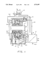
- FIG. 1 illustrates diagrammatically and in partial sectional view a braking system in accordance with one form of the invention in an idling mode, while FIG. 2 shows the system in a braking mode.
- the retarder 1 includes a rotor R and a stator S, and the retarder housing 2 forms a main space 2.1 containing an oil sump and additionally a side space 2.4.
- a partition 2.2 separates main space 2.1 from a riser duct 2.3.
- riser duct 2.3 communicates with the working space of the retarder 1 by way of its stator S.
- the braking system includes a control device, the control device including as a major part a proportional valve 3 with integrated 3/2-valve.
- a line 3.1 establishes a connection between main space 2.1 and proportional valve 3.
- a line 3.2 runs to an oil side space 3.3 serving as an oil separator and connecting to a venting duct 3.4 which communicates with a leakage oil return line of the bearings 3.5.
- a heat exchanger 4 connects via a line 4.1 to the working space of the retarder 1 and via line 4.2 to the riser duct 2.3.
- Heat exchanger 4 has an inlet 4.3 and an outlet 4.4 for the cooling water.
- the invention in the form illustrated, comprises retarder 1 featuring between rotor R and stator S a gap 1.1. Between said gap 1.1 and the main space 2.1 of the sump, a conveying connection can be established or interrupted. Shown in the duct connected to the gap 1.1 is a choke 1.2, furthermore--as an extremely important element--a 2/2-valve 1.3. Valve 1.3 can be connected, via outlet 1.4, to the main space 2.1 and via a line 1.5 to the 3/2-way valve.
- the gap shut-off valve In the nonbraking operation, valve 1.3--hereafter referred to as the "gap shut-off valve"--remains open, and is kept open by a spring 1.6.
- the oil levels in main space 2.1, in side space 2.4 as well as in riser duct 2.3 are identical.
- the air flow generated in the working space of the retarder is vented via sump line 3.1.
- a particularly favorable ancillary effect occurs because the working space of the retarder 1 sucks oil-air mixture through the riser duct 2.3.
- An oil-air mixture forms in the circulation and also in riser duct 2.3 itself. Attributable to centrifugal force, a certain amount of oil separates in the working space of retarder 1. This leads both to a reduction of the power loss and to a cooling effect.
- Line 1.5 is pressurized as well through 3/2-way valve 3, causing the gap shut-off valve 1.3 to close. Hence, the open connection between the working space of retarder 1 and the main space 2.1 is blocked. Reference is made to the arrows indicating the direction of pressure or flow.
- forming in the riser line is an oil-air mixture that proceeds into the working space of the retarder, forms there an oil film on the inside walls of the working space, which leads to a reduction of the power loss and a cooling of the retarder.
- the generated heat from the power loss is removed by way of the heat exchanger.
Landscapes
- Engineering & Computer Science (AREA)
- Mechanical Engineering (AREA)
- General Engineering & Computer Science (AREA)
- Physics & Mathematics (AREA)
- Fluid Mechanics (AREA)
- Transportation (AREA)
- Braking Arrangements (AREA)
- Transmission Of Braking Force In Braking Systems (AREA)
Applications Claiming Priority (2)
| Application Number | Priority Date | Filing Date | Title |
|---|---|---|---|
| DE4442219.9 | 1994-11-26 | ||
| DE4442219A DE4442219A1 (de) | 1994-11-26 | 1994-11-26 | Bremsanlage mit einem hydrodynamischen Retarder, insbesondere für Kraftfahrzeuge |
Publications (1)
| Publication Number | Publication Date |
|---|---|
| US5771997A true US5771997A (en) | 1998-06-30 |
Family
ID=6534289
Family Applications (1)
| Application Number | Title | Priority Date | Filing Date |
|---|---|---|---|
| US08/562,962 Expired - Fee Related US5771997A (en) | 1994-11-26 | 1995-11-27 | Braking system in conjunction with a hydrodynamic retarder, specifically for motor vehicles |
Country Status (4)
| Country | Link |
|---|---|
| US (1) | US5771997A (ja) |
| EP (1) | EP0713811B1 (ja) |
| JP (1) | JPH08207740A (ja) |
| DE (2) | DE4442219A1 (ja) |
Cited By (10)
| Publication number | Priority date | Publication date | Assignee | Title |
|---|---|---|---|---|
| US20030188940A1 (en) * | 2000-07-07 | 2003-10-09 | Hans Jonsson | Hydrodynamic brake |
| WO2002090163A3 (en) * | 2001-05-10 | 2003-11-27 | Volvo Lastvagnar Ab | Hydraulic vehicle retarder and method of controlling such retarder |
| US20040195063A1 (en) * | 2001-03-22 | 2004-10-07 | Simonis John C | Fluid coupled vehicle speed retarder |
| US20050016804A1 (en) * | 2001-10-17 | 2005-01-27 | Klause Vogelsang | Hydrodynamic braking system provide with a retarder |
| US20050155828A1 (en) * | 2002-07-03 | 2005-07-21 | Johnny Farm | Hydrodynamic brake |
| CN102996686A (zh) * | 2012-12-04 | 2013-03-27 | 华南农业大学 | 消除液力缓速器油气混合的油路结构及其工作方法 |
| WO2015158104A1 (en) * | 2014-04-16 | 2015-10-22 | Tianwei Li | Hydraulic damper |
| WO2018189203A1 (en) | 2017-04-11 | 2018-10-18 | Dana Belgium N.V. | Hydrodynamic retarder system |
| WO2018197586A1 (en) | 2017-04-26 | 2018-11-01 | Dana Belgium N.V. | Hydrodynamic retarder system and method of controlling a hydrodynamic retarder system |
| WO2024188779A1 (de) * | 2023-03-10 | 2024-09-19 | Voith Patent Gmbh | Hydrodynamische retarder mit füllrohr |
Families Citing this family (11)
| Publication number | Priority date | Publication date | Assignee | Title |
|---|---|---|---|---|
| SE523008C2 (sv) * | 2002-07-03 | 2004-03-23 | Scania Cv Ab | Hydrodynamisk broms |
| DE102005050480B3 (de) * | 2005-10-21 | 2007-01-18 | Voith Turbo Gmbh & Co. Kg | Steuerluftsystem und Verfahren zum Steuern des Steuerluftdruckes in einem solchen System |
| EP1970788A3 (de) * | 2007-03-16 | 2010-03-10 | Voith Turbo H + L Hydraulic GmbH & Co. KG | Pneumatikregeleinrichtung und Verfahren hierfür |
| DE102008000901A1 (de) | 2008-04-01 | 2009-10-08 | Zf Friedrichshafen Ag | Steuergehäuse für eine hydraulische Retardersteuerung |
| DE102012002038A1 (de) * | 2012-02-03 | 2013-08-08 | Voith Patent Gmbh | Hydrodynamischer Retarder |
| DE102012002039A1 (de) | 2012-02-03 | 2013-08-08 | Voith Patent Gmbh | Hydrodynamischer Retarder |
| CN104405795B (zh) * | 2014-11-28 | 2016-09-28 | 宁波华盛汽车部件有限公司 | 液力缓速器上的液压油循环系统 |
| CN105570351B (zh) * | 2016-03-10 | 2018-03-30 | 合肥三叶机械有限公司 | 无摩擦防抱死气压刹车装置 |
| EP4292891A1 (en) * | 2022-06-17 | 2023-12-20 | ZF CV Systems Europe BV | Proportionality valve for a hydraulic endurance brake system for a vehicle, in particular utility vehicle, hydraulic endurance brake system and vehicle, in particular utility vehicle |
| DE102022125358A1 (de) * | 2022-09-30 | 2024-04-25 | Voith Patent Gmbh | Arbeitsmediumkreislauf für einen Retarder |
| DE102023105956B4 (de) * | 2023-03-10 | 2024-09-19 | Voith Patent Gmbh | Hydrodynamischer Retarder mit Arbeitsmediumtank |
Citations (9)
| Publication number | Priority date | Publication date | Assignee | Title |
|---|---|---|---|---|
| US3180692A (en) * | 1961-02-24 | 1965-04-27 | Voith Getriebe Kg | Filling controlled hydrodynamic fluid circuit |
| US3547231A (en) * | 1968-09-20 | 1970-12-15 | Eaton Yale & Towne | Fluid retarder |
| US3951242A (en) * | 1968-11-14 | 1976-04-20 | Maschinenfabrik Augsburg-Nurnberg Ag | Hydraulic brake for heavy vehicles |
| US3958671A (en) * | 1973-12-08 | 1976-05-25 | Voith Getriebe Kg | Hydrodynamic brake system |
| DE2927582A1 (de) * | 1979-07-07 | 1981-01-08 | Voith Getriebe Kg | Hydrodynamische bremse |
| DE3028429A1 (de) * | 1980-07-26 | 1982-02-11 | Voith-Turbo Gmbh & Co Kg, 7180 Crailsheim | Hydrodynamische drehmomentuebertragungseinheit, insbesondere hydrodynamische bremse |
| US4864872A (en) * | 1988-06-13 | 1989-09-12 | Stahl Jere F | Hydraulic dynamometer |
| DE3940825A1 (de) * | 1989-12-11 | 1991-06-13 | Voith Turbo Kg | Hydrodynamischer retarder |
| DE4408350A1 (de) * | 1994-03-11 | 1994-10-06 | Voith Turbo Kg | Antriebseinheit und Verfahren zum Betreiben der Antriebseinheit |
Family Cites Families (1)
| Publication number | Priority date | Publication date | Assignee | Title |
|---|---|---|---|---|
| DE2710927A1 (de) * | 1977-03-12 | 1978-09-14 | Daimler Benz Ag | Hydrodynamischer retarder fuer fahrzeuge, insbesondere fuer kraftfahrzeuge |
-
1994
- 1994-11-26 DE DE4442219A patent/DE4442219A1/de not_active Withdrawn
-
1995
- 1995-11-20 DE DE59507814T patent/DE59507814D1/de not_active Expired - Fee Related
- 1995-11-20 EP EP95118236A patent/EP0713811B1/de not_active Expired - Lifetime
- 1995-11-27 JP JP7307951A patent/JPH08207740A/ja active Pending
- 1995-11-27 US US08/562,962 patent/US5771997A/en not_active Expired - Fee Related
Patent Citations (9)
| Publication number | Priority date | Publication date | Assignee | Title |
|---|---|---|---|---|
| US3180692A (en) * | 1961-02-24 | 1965-04-27 | Voith Getriebe Kg | Filling controlled hydrodynamic fluid circuit |
| US3547231A (en) * | 1968-09-20 | 1970-12-15 | Eaton Yale & Towne | Fluid retarder |
| US3951242A (en) * | 1968-11-14 | 1976-04-20 | Maschinenfabrik Augsburg-Nurnberg Ag | Hydraulic brake for heavy vehicles |
| US3958671A (en) * | 1973-12-08 | 1976-05-25 | Voith Getriebe Kg | Hydrodynamic brake system |
| DE2927582A1 (de) * | 1979-07-07 | 1981-01-08 | Voith Getriebe Kg | Hydrodynamische bremse |
| DE3028429A1 (de) * | 1980-07-26 | 1982-02-11 | Voith-Turbo Gmbh & Co Kg, 7180 Crailsheim | Hydrodynamische drehmomentuebertragungseinheit, insbesondere hydrodynamische bremse |
| US4864872A (en) * | 1988-06-13 | 1989-09-12 | Stahl Jere F | Hydraulic dynamometer |
| DE3940825A1 (de) * | 1989-12-11 | 1991-06-13 | Voith Turbo Kg | Hydrodynamischer retarder |
| DE4408350A1 (de) * | 1994-03-11 | 1994-10-06 | Voith Turbo Kg | Antriebseinheit und Verfahren zum Betreiben der Antriebseinheit |
Cited By (16)
| Publication number | Priority date | Publication date | Assignee | Title |
|---|---|---|---|---|
| US20030188940A1 (en) * | 2000-07-07 | 2003-10-09 | Hans Jonsson | Hydrodynamic brake |
| US6923301B2 (en) * | 2000-07-07 | 2005-08-02 | Scania Cv Ab | Hydrodynamic brake |
| US20040195063A1 (en) * | 2001-03-22 | 2004-10-07 | Simonis John C | Fluid coupled vehicle speed retarder |
| WO2002090163A3 (en) * | 2001-05-10 | 2003-11-27 | Volvo Lastvagnar Ab | Hydraulic vehicle retarder and method of controlling such retarder |
| US20050016804A1 (en) * | 2001-10-17 | 2005-01-27 | Klause Vogelsang | Hydrodynamic braking system provide with a retarder |
| US20050155828A1 (en) * | 2002-07-03 | 2005-07-21 | Johnny Farm | Hydrodynamic brake |
| US7097013B2 (en) * | 2002-07-03 | 2006-08-29 | Scania Cv Ab (Publ) | Hydrodynamic brake |
| CN102996686B (zh) * | 2012-12-04 | 2015-09-30 | 华南农业大学 | 消除液力缓速器油气混合的油路结构及其工作方法 |
| CN102996686A (zh) * | 2012-12-04 | 2013-03-27 | 华南农业大学 | 消除液力缓速器油气混合的油路结构及其工作方法 |
| WO2015158104A1 (en) * | 2014-04-16 | 2015-10-22 | Tianwei Li | Hydraulic damper |
| US10138959B2 (en) | 2014-04-16 | 2018-11-27 | Tianwei Li | Hydraulic damper |
| WO2018189203A1 (en) | 2017-04-11 | 2018-10-18 | Dana Belgium N.V. | Hydrodynamic retarder system |
| US11173882B2 (en) * | 2017-04-11 | 2021-11-16 | Dana Belgium N.V. | Hydrodynamic retarder system |
| WO2018197586A1 (en) | 2017-04-26 | 2018-11-01 | Dana Belgium N.V. | Hydrodynamic retarder system and method of controlling a hydrodynamic retarder system |
| US11312341B2 (en) | 2017-04-26 | 2022-04-26 | Dana Belgium N.V. | Hydrodynamic retarder system and method of controlling a hydrodynamic retarder system |
| WO2024188779A1 (de) * | 2023-03-10 | 2024-09-19 | Voith Patent Gmbh | Hydrodynamische retarder mit füllrohr |
Also Published As
| Publication number | Publication date |
|---|---|
| EP0713811A1 (de) | 1996-05-29 |
| DE59507814D1 (de) | 2000-03-23 |
| EP0713811B1 (de) | 2000-02-16 |
| DE4442219A1 (de) | 1995-06-01 |
| JPH08207740A (ja) | 1996-08-13 |
Similar Documents
| Publication | Publication Date | Title |
|---|---|---|
| US5771997A (en) | Braking system in conjunction with a hydrodynamic retarder, specifically for motor vehicles | |
| US4175647A (en) | Hydrodynamic retarder for vehicles, especially for motor vehicles | |
| CN105121238B (zh) | 液力减速器 | |
| US3774735A (en) | Hydrodynamic retarder for vehicles | |
| US2827989A (en) | Hydrodynamic drive and brake | |
| US3768613A (en) | Fluid clutch housing | |
| JP2006502900A (ja) | リターダ付き駆動ユニット | |
| US5090523A (en) | Hydrodynamic retarder | |
| GB1597404A (en) | Auxiliary oil supply systems | |
| KR101093647B1 (ko) | 물 리타더를 구비한 자동차 구동장치 | |
| US6817455B1 (en) | Retarder system | |
| US4324320A (en) | Power limiting control for retarder with friction brake | |
| US3888335A (en) | Hydrodynamic retarder for vehicles, especially for motor vehicles | |
| CN101479142A (zh) | 液动力减速器 | |
| US20170327099A1 (en) | Working medium circuit for a hydrodynamic machine | |
| US2287130A (en) | Hydrodynamic brake mechanism | |
| US4432442A (en) | Hydrodynamic torque-transfer unit, especially a hydrodynamic brake | |
| CN219588001U (zh) | 流体动力学的缓速器 | |
| GB2125952A (en) | A cooling circuit for internal combustion engines | |
| JPH05501444A (ja) | 液圧システムにおける運転状態改善のための装置 | |
| JP2009541127A (ja) | 流体リターダ | |
| JPH11236947A (ja) | 回転振動ダンパ又は振動を制動しかつ回転弾性を有するクラツチ | |
| US20050016804A1 (en) | Hydrodynamic braking system provide with a retarder | |
| EP1305537B1 (en) | Hydrodynamic brake | |
| US20040238301A1 (en) | Method for emptying a hydrodynamic retarder in an accelerated manner and hydrodynamic retarder |
Legal Events
| Date | Code | Title | Description |
|---|---|---|---|
| AS | Assignment |
Owner name: VOITH TURBO GMBH, GERMANY Free format text: ASSIGNMENT OF ASSIGNORS INTEREST;ASSIGNORS:FRIEDRICH, JURGEN;MULLER, WOLFGANG;REEL/FRAME:007836/0539 Effective date: 19951215 |
|
| FEPP | Fee payment procedure |
Free format text: PAYOR NUMBER ASSIGNED (ORIGINAL EVENT CODE: ASPN); ENTITY STATUS OF PATENT OWNER: LARGE ENTITY |
|
| FPAY | Fee payment |
Year of fee payment: 4 |
|
| FPAY | Fee payment |
Year of fee payment: 8 |
|
| REMI | Maintenance fee reminder mailed | ||
| LAPS | Lapse for failure to pay maintenance fees | ||
| STCH | Information on status: patent discontinuation |
Free format text: PATENT EXPIRED DUE TO NONPAYMENT OF MAINTENANCE FEES UNDER 37 CFR 1.362 |
|
| FP | Lapsed due to failure to pay maintenance fee |
Effective date: 20100630 |