US5772306A - Illuminating device with a light distributing lens - Google Patents
Illuminating device with a light distributing lens Download PDFInfo
- Publication number
- US5772306A US5772306A US08/660,740 US66074096A US5772306A US 5772306 A US5772306 A US 5772306A US 66074096 A US66074096 A US 66074096A US 5772306 A US5772306 A US 5772306A
- Authority
- US
- United States
- Prior art keywords
- light
- lens
- axis
- vehicle
- light distribution
- Prior art date
- Legal status (The legal status is an assumption and is not a legal conclusion. Google has not performed a legal analysis and makes no representation as to the accuracy of the status listed.)
- Expired - Fee Related
Links
Images






Classifications
-
- F—MECHANICAL ENGINEERING; LIGHTING; HEATING; WEAPONS; BLASTING
- F21—LIGHTING
- F21S—NON-PORTABLE LIGHTING DEVICES; SYSTEMS THEREOF; VEHICLE LIGHTING DEVICES SPECIALLY ADAPTED FOR VEHICLE EXTERIORS
- F21S41/00—Illuminating devices specially adapted for vehicle exteriors, e.g. headlamps
- F21S41/20—Illuminating devices specially adapted for vehicle exteriors, e.g. headlamps characterised by refractors, transparent cover plates, light guides or filters
- F21S41/25—Projection lenses
- F21S41/27—Thick lenses
Definitions
- the present invention relates to an illuminating device with a light distributing lens and, more particularly, to an illuminating device adapted for use in a vehicle.
- a headlamp for a vehicle in which a light distribution can obtain a desired dispersion in the right and left directions without blurring the boundary between bright and dark portions on the upper edge of the illumination pattern, has been proposed in Japanese Patent Publication No. Hei 4-10163. This is designed to obtain a light distribution dispersing in the right and left directions of a vehicle with a projecting lens by projecting forward a shading edge of a light reflected by a reflective mirror.
- the present invention has an object to improve an illuminating device.
- the present invention has another object to provide an illuminating device which provides a clear edge in the vertical direction of the light distribution and dispersion at the edge in the horizontal direction.
- a lens for a light distribution has a light incident surface and a light exit surface, where the exit surface is formed in an aspheric surface so that an aberration in the horizontal direction can be larger than an aberration in the vertical direction of the exit surface.
- a peripheral portion in the horizontal direction is blurrier than a peripheral portion in the vertical direction.
- a radius of curvature of the outer periphery of a horizontal cross-section of the aspheric lens surface is formed to be smaller than a radius of curvature of the outer periphery of a vertical cross-section.
- the aspheric lens surface is made of a curved surface that is formed by combining ellipsoids, and the outer periphery of the vertical cross-section of the same lens surface is formed in an ellipsoid.
- the lens for the light distribution has a total reflective surface inclined by a predetermined angle with respect to the vertical surface of the light axis, and the light distribution formed by the outgoing light from the exit surface is formed to be located slantingly in the vertical direction of the light axis based on the reflection by a total reflective surface.
- the total reflective surface is formed to stray off the light-axis direction gradually as it goes closer to the exit surface, and also the inclining angle is formed to be gradually smaller as it goes closer to the exit surface.
- FIGS. 1(a) to 1(c) are schematic views of a principle of the present invention.
- FIG. 2 is a perspective view showing a main portion of a lens for a hot zone light distribution of a first embodiment of the present invention
- FIG. 3 is a vectorial view showing an aberration of the lens for the hot zone light distribution of FIG. 2;
- FIGS. 4(a) and 4(b) are perspective views showing an example where the lens for the hot zone light distribution of FIG. 2 is applied to a headlamp for a vehicle;
- FIG. 5 is a perspective view showing a first modification of the first embodiment of the present invention.
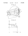
- FIG. 6 is a view showing a graph for explanation of the first modification of FIG. 5;
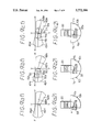
- FIGS. 7(a) to 7(d) are schematic views showing a second modification of the first embodiment of the present invention.
- FIGS. 8(a) and 8(b) are schematic views showing a second embodiment of the present invention.
- FIGS. 9(a1) to 9(c2) are schematic views explaining the second embodiment of the present invention.
- FIGS. 10(a) and 10(b) are perspective views showing a third embodiment of the present invention.
- FIGS. 11(a) to 11(b) are perspective views showing a fourth embodiment of the present invention.
- FIGS. 1(a) to 1(c) showing the principle of the present invention
- a light-axis of a lens 10 as shown in FIG. 1(a) is a z-axis
- a horizontal direction of the lens 10 is an x-axis
- a vertical direction of the lens 10 is a y-axis
- light is designed to be emitted from a focal position f of this lens 10.
- a cross-sectional shape in the vertical direction is so designed as to make a beam emitted from the lens 10 substantially a parallel beam as shown in FIG. 1(b).
- this aberration means that light emitted from one point does not converge on one point
- outgoing light of the horizontal cross-section of this lens 10 is so designed that a beam emitted from the lens 10 as shown in FIG. 1(c) cannot become a parallel beam. That is a cross-sectional shape in the horizontal direction is so designed that an aberration at the infinite-point becomes larger than the aberration of the vertical cross-section.
- the lens 10 is not limited to a one-sided convex lens as shown in FIG. 1(a), but it can also be formed by combining biconvex lenses or concaveconvex lenses.
- FIG. 2 shows a perspective view of a lens of the first embodiment.
- the lens 10 according to the present first embodiment is shaped like a roughly one quarter (1/4) of a cone, made of material having excellent light transmittance, for example, polycarbonate or acrylic resin material.
- This lens 10 is composed of a light incident surface 11 where a light flux emitted from a light source not shown in the figure enters in the z-axis direction (a light-axis), a light exit surface 12 forming a lens surface of an aspheric surface described below, a side total reflective surface 13 in the vertical direction with respect to the light-axis, and an upper total reflective surface 14 in the horizontal direction with respect to the light-axis.
- a vertical cross-sectional (z-y plane) outer periphery A of the exit surface 12 is shaped like a lens having a focal point in the vicinity of a crossing point 13a between the incident surface 11 and the z-axis.
- a horizontal cross-sectional (z-x plane) outer periphery B has a focal point in the vicinity of a crossing point 13a between the incident surface 11 and the z-axis, however, the shape of the lens has a larger aberration than the vertical cross-sectional (z-y plane) outer periphery A.
- the horizontal cross-sectional (z-x plane) outer periphery B is a curved surface shifting gradually along the y-axis of the vertical cross-sectional (z-y plane) outer periphery A, while the vertical cross-sectional (z-y plane) outer periphery A is a curved surface shifting gradually along the x-axis of the horizontal cross-sectional (z-x plane) outer periphery B. Specifically, if a radius of curvature of the horizontal cross-sectional (z-x plane) outer periphery B is made smaller than a radius of curvature of the vertical cross-sectional (z-y plane) outer periphery A, the direction and the size of the aberration is in a state shown in FIG. 3.
- FIG. 3 is a view where the aberration of the beam seen from the incident direction (z-axis direction) of a light of the exit surface 12 is indicated by vectors (arrow marks in the figure). From FIG. 3, it is understood that the aberration of the lens 10 becomes larger in the horizontal direction (x-axis direction), the aberration conversely becomes smaller as it goes closer to the vertical direction (y-axis direction). Therefore, the light distribution does not disperse widely in the vertical direction (y-axis direction) in order not to cause glaring against the on-coming vehicles running in the opposite lane, however it disperses widely in the horizontal direction (x-axis direction) which causes a blurred light distribution at the peripheral portions. Thus, light intensity in the horizontal direction (x-axis direction) so smoothly decreases that uneven distribution of light which may be caused by a sudden change of the light intensity can be prevented.
- FIGS. 4(a) and 4(b) are views showing an example which adopts the lens 10 to a low beam of a headlamp for a vehicle.
- the headlamp comprises an optical fiber 30 emitting a light by entering the light generated by an electrically-driven light source not shown in the figure, a lens 20 for a flat light distribution forming a flat light distribution 41 (a light distribution made of very widely area dispersed light right and left below the horizontal-axis H--H of FIG.
- FIG. 4(b) shows a light distribution 40 formed by the light irradiated by the lens 20 for the flat distribution and the lens 10 for the hot zone light distribution.
- the lens 20 for the flat light distribution made of such a material having excellent light transmittance as a polycarbonate or acrylic resin material is substantially formed in the shape of a fan.
- This lens 20 for the flat light distribution comprises an incident surface 21 partially glued with a transparent adhesive via a shade 32 at the upper portion of the exit surface 31 of the optical fiber 30, an exit surface 22 forming a biconvex lens for upper and lower portions, left and right side surfaces 23, 24 forming reflective surfaces, respectively, and a bottom surface 25 forming the same reflective surface.
- the focal point of this lens 20 for the flat light distribution is designed to be placed in the vicinity of the incident surface 21.
- the lens 10 for the hot zone light distribution comprises an incident surface 11 partially glued with a transparent adhesive via a shade 33 at the lower portion of the optical fiber 30, an exit surface 12 forming the direction and the size of the aberration as shown in FIG. 3 by making a radius of curvature of the horizontal cross-sectional (z-x plane) outer periphery B smaller than a radius of curvature of the vertical cross-sectional (z-y plane) outer periphery A as shown in FIG. 2, a side total reflective surface 13 forming an inclined surface inclining in the clockwise direction by 7.5° with respect to the vertical surface along the irradiating direction, and another upper total reflective surface 14 forming a horizontal surface.
- incident surfaces 11 and 21 may be disposed as closely as possible to the optical fiber 30 without using adhesives.
- the upper total reflective surface 14 is adjacent to the side total reflective surface 13 as a boundary of a line c along the irradiating direction at the upper edge of the side total reflective surface 13.
- the shade 33 has a cut line 34 inclining by a predetermined angle (for example, 15°) to the lower right toward the irradiating direction, with respect to the horizontal surface.
- the focal position F of the lens surface in the vertical direction of the exit surface 12 is placed near the incident surface 11, and is designed to be positioned at a crossing point between the side total reflective surface 13 and the cut line 34 of the shade 33.
- the focal position of the lens surface in the horizontal direction of the exit surface 12 is set near the focal position F of the lens surface in the vertical direction.
- the hot zone light distribution 42 has an area 42a formed by direct light emitted from the direct exit surface 12 without reflecting on the side total reflective surface 13 and the upper total reflective surface 14 and an area 42a z dispersing blurredly due to the aberration. Because the cut line 34 of the shade 33 inclines based on the focal position F of the exit surface 12 by a predetermined angle (for example, 15° ) to the lower right toward the irradiating direction, these areas 42a and 42a z have the upper edge a inclining to the upper left by 15° from the horizontal axis H--H as shown in FIG. 4(b).
- the hot zone light distribution 42 has an area 42b formed by reflected light emitted from the exit surface 12 after reflecting on the side total reflective surface 13 and an area 42b z dispersing blurredly due to the aberration. Based on the focal position F of the exit surface 12, as shown in FIG. 4(b), these areas 42b and 42b z are positioned having a substantially horizontal upper edge b immediately below the horizontal axis H--H.
- the hot zone light distribution 42 has an area 42c formed by a reflected light emitted from the exit surface 12 after reflecting on the upper total reflective surface 14 and an area 42c z dispersing blurredly due to the aberration.
- an area 42d formed by re-reflected light emitted from the exit surface 12 after reflecting on the side total reflective surface 13 again, posterior to reflecting on the upper total reflective surface 14 and an area 42d z dispersing blurredly due to the aberration.
- These areas 42c, 42c z , 42d, and 42d z are formed, based on the focal position F of the exit surface 12, as shown in FIG. 4 (b), immediately below the respective areas 42a and 42a z , and immediately below the respective areas 42b and 42b z .
- the hot zone light distribution illuminating a far distant area without causing glaring against the on-coming vehicle can be obtained whether it is the right or the left traffic system by positioning the areas 42a and 42a z located at the upper side to the left side in case of a vehicle running on the left lane and by positioning the same areas to the right side in case of a vehicle running on the right lane.
- a reflective surface the side total reflective surface 13 in case of FIG.
- the shape of the lens surface of the exit surface 12 makes the aberration in the vertical direction (z-y plane) substantially zero in the present first modified embodiment.
- the shape of the lens surfaces of the exit surface 12 in order to make the aberration in the vertical direction (z-y plane) to be substantially zero, it is desirable for the shape of the lens surfaces of the exit surface 12 to be a curved surface composed of a combination of elliptical-shaped lens surface of the exit surface 12.
- FIG. 5 is a view showing a lens 10a for a hot zone light distribution shaped like a curved surface composed of a combination of elliptical-shaped lens surfaces of the exit surface.
- the longer diameter of the outer peripheral ellipsoid C of the vertical cross-section (z-y plane) of the lens 10a for the hot zone light distribution is a
- the shorter diameter is b 0
- the original points of the x-axis, the y-axis, and the z-axis are taken at the vertex of the lens 10a for the hot zone light distribution
- the outer peripheral ellipsoid C of the vertical cross-section (z-y plane) is expressed by the following equation 3.
- the radius of curvature of the outer peripheral ellipsoid D of the horizontal cross-section becomes smaller than the radius of curvature of the outer peripheral ellipsoid C of the vertical cross-section, thus, the aberration shown in FIG. 3 is provided.
- the shorter diameter b 2 has to be linearly changed from b 0 to b 1 as ⁇ becomes closer to ⁇ /2 (x-axis) from zero (y-axis), or as shown with a curved line (b) of FIG. 6, the shorter diameter b2 has to be non-linearly changed from b 0 to b 1 as ⁇ becomes closer to ⁇ /2 (x-axis) from zero (y-axis), or as shown with a curved line (c) in FIG.
- the shorter diameter b 2 when ⁇ is between zero (y-axis) and nearby ⁇ /2 (x-axis), the shorter diameter b 2 should be left as b 0 , however, the shorter diameter b 2 should be abruptly changed to b 1 between nearby ⁇ /2 (x-axis) and ⁇ /2 (x-axis).
- the curved line (c) in FIG. 6 when the shorter diameter b 2 is abruptly changed to b 1 between nearby ⁇ /2 (x-axis) and ⁇ /2 (x-axis), the aberration is not apt to occur furthermore in the vertical direction, which prevents glaring against the on-coming vehicles running in the opposite lane.
- the size of the aberration is adjusted by changing the shorter diameters of the outer peripheral ellipsoids of the vertical cross-section and the horizontal cross-section of the lens 10a for the hot zone light distribution
- the size of the aberration can be adjusted by changing the longer diameter, or the size of the aberration can be adjusted by changing both the longer and shorter diameters at the same time.
- the lens surface of the exit surface is in the shape of an ellipsoid in order to adjust the aberration, however, it may be able to be shaped in a curved surface other than an ellipsoidal shape.
- the lens 10, 10a for the hot zone light distribution of the first embodiment and the first modification it is substantially shaped like one quarter (1/4) of a cone, and also the side total reflective surfaces 13 and 13a are disposed inclining to the left side with respect to the light-axis direction (z-axis direction) by 7.5°, accordingly, the aberration direction is primarily in the left to upper left direction, which inclines the hot zone light distribution toward the left (FIGS. 4(a) and 4(b)).
- a modification is performed on the total reflective surface of a side surface as shown in FIGS. 7(a) and 7(b).
- FIG. 7(a) is a view showing light distribution characteristics when a side total reflective surface of a lens 10b for hot zone light distribution is modified.
- FIG. 7(b) shows a perspective view of the lens 10b for the hot zone light distribution taken from the above
- FIG. 7(c) shows a shape of an incident surface 11b of the lens 10b for hot zone light distribution
- FIG. 7(d) is a view showing a cross-sectional shape taken along the line 7(d)--7(d) in FIG. 7(b).
- the side total reflective surface 13b of the lens 10b for the hot zone light distribution has, as shown with a two-dot line in FIG. 7(c) and FIG. 7(b) and FIG. 7(d), an inclined surface 13b 1 inclining toward the left side by 7.5° with respect to the vertical surface along the irradiating direction, and a cut line 34b of a shade 33b also inclines toward the lower right by 15° along the irradiating direction.
- the light distribution characteristic has an area formed by direct light 42a 1 , an area 42b 1 (inside of the two-dot line of FIG. 7(a)) formed by the reflective light oh the inclined surface 13b 1 , an area 42c 1 , formed by the reflective light on an upper total reflective surface 14b, and an area 42d 1 (inside of the two-dot line of FIG. 7(a)) formed by re-reflected light, i.e., the reflective light on the upper surface reflective surface 14b reflected again on the inclined surface 13b 1 .
- FIG. 7(a) there is an area dispersing blurredly due to the aberration of the lens 10b for the hot zone light distribution as shown in FIG. 4(b), however, its illustration is omitted in this case.
- the right edge portion of the hot zone light distribution can be extended in the right direction, however, as shown with a broken line of FIG. 7(a), it is extended to the lower right side (areas 42b 2 and 42d 2 inside a broken line of FIG. 7 (a)) owing to the aberration of the lens 10b for the hot zone light distribution, so that visibility of a distant area at the right side decreases.
- the inclined surface 13b 3 of the cross-section F--F becomes an inclined surface of 4.5°, thus a smooth surface can be continuously formed between a point Z 1 at the incident side of the light of the inclined surface 13b 3 and a point Z 2 at the exit side.
- the surface between the point Z 1 at the incident side and the point Z 2 at the exit side can be formed in plural surfaces, or may be formed in a curved surface.
- the hot zone light distribution illuminating a far distant area without causing glaring against the on-coming vehicle can be obtained whether it is the right or the left traffic system by positioning the area 42a 1 , located at the upper side to the left side in the case of a vehicle running in the left lane and by positioning the same area to the right side in the case of a vehicle running in the right lane.
- a reflective surface the inclined surface 13b 3 in case of FIG. 7(d) in the vertical direction is concerned, it should be disposed inclined to the left side for a vehicle running in the left lane and to the right side for a vehicle running in the right lane from the incident surface of the lens 10b for the hot zone light distribution.
- two lenses substantially shaped like one quarter (1/4) of a cone can be combined to make them one lens substantially shaped like one half (1/2) of a cone, so that it can be a lens for hot zone light distribution.
- FIG. 8(a) two lenses substantially shaped like one quarter (1/4) of a cone are combined to make a lens substantially shaped like one half (1/2) of a cone.
- This lens may be used for hot zone light distribution applied to a low beam of a head lamp for a vehicle.
- the present second embodiment in order to make the lens in the shape of a substantially one half (1/2) of a cone, comprises the lens 10b for the hot zone light distribution as in the foregoing embodiments and an additional lens 10c for hot zone light distribution having a total reflective surface vertically disposed with respect to the light-axis at a side surface.
- FIG. 8(a) illustrates a headlamp for a vehicle, whose headlamp comprises the optical fiber 30 emitting light by entering the light generated by a light source, not shown in the figure, the lens 20 for flat light distribution forming the flat light distribution 41 by entering the light transmitted through this optical fiber 30, the lens 10b for the hot zone light distribution forming a hot zone light distribution, and another lens 10c for the hot zone light distribution.
- FIG. 8(b) shows a light distribution 40A formed by the light irradiated by the lens 20 for the flat distribution, the lens 10 for the hot zone light distribution and another lens 10c for the hot zone light distribution.
- FIGS. 8(a) and 8(b) since the lens 20 for the flat light distribution, the optical fiber 30, the shades 32, 33 and the flat light distribution 41 are respectively the same as the lens 20 for the flat light distribution, the optical fiber 30, the shades 32, 33 and the flat light distribution 41 in the first embodiment of FIG. 4, explanations therefor are omitted. Also, in FIGS. 8(a) and 8(b), since the lens 10b for the hot zone light distribution and hot zone light distributions 43a 1 , 43b 3 , 43c 1 , and 43d 3 are respectively the same as the lens 10b for the hot zone light distribution and the hot zone light distributions 42a 1 , 42b 3 , 42c 1 , and 42d 3 of FIG. 7, explanations therefor are omitted.
- the respective hot zone light distributions 43a 1z , 43b 3z , 43c 1z , and 43d 3z , of FIG. 8(b) show areas of the peripheries of respective hot zone distributions 42a 1 , 42b 3 , 42c 1 , and 42d 3 dispersing blurredly owing to the aberration.
- the hot distribution 50 has an area 50a formed by direct light emitted from the direct exit surface 12c without being reflected on the side total reflective surface 13c and the upper total reflective surface 14c. Since the cut line 34 of the shade 33 inclines, based on the focal position of the exit surface 12c, by a predetermined angle (for example, 15°) to the lower right toward the irradiating direction, this area has an upper edge c inclining to the upper left by 15° from the horizontal axis H--H as shown in FIG. 8(b).
- the hot zone light distribution 50 has an area 50b formed by reflected light emitted from an exit surface 12c after reflecting on a side total reflective surface 13c. Based on the focal position of the exit surface 12c, as shown in FIG. 8(b), this area 50b is positioned to have a substantially horizontal upper edge d immediately below the horizontal axis H--H.
- the hot zone light distribution 50 has an area 50c formed by reflected light emitted from the exit surface 12c after being reflected on the upper total reflective surface 14c.
- it has an area 50d formed by a re-reflected light emitted from the exit surface 12c after being reflected on the side total reflective surface 13c again, posterior to reflecting on the upper total reflective surface 14c.
- These areas 50c and 50d are respectively formed, based on the focal position of the exit surface 12c, as shown in FIG. 8(b), immediately below the respective areas 50a and 50b.
- FIGS. 9(a1) to 9(c2) is a view showing a difference in the characteristics of each hot zone light distribution between the case where one lens substantially shaped like a quarter (1/4) of a cone is employed as a lens for the hot zone light distribution and the case where one lens substantially shaped like one half (1/2) of a cone by combining two lenses substantially shaped like a quarter (1/4) of a cone.
- FIG. 9(a2) shows the shapes of the incident surface 11b of the lens 10b for the hot zone light distribution and the shade 33 of FIG. 7(b), while FIG. 9(a2) shows a characteristic of the hot zone light distribution.
- FIG. 9(a2) shows the shapes of the incident surface 11b of the lens 10b for the hot zone light distribution and the shade 33 of FIG. 7(b), while FIG. 9(a2) shows a characteristic of the hot zone light distribution.
- FIG. 9(b2) shows the shapes of the incident surfaces 11b and 11c of the lenses 10b and 10c for the hot zone light distribution, and the shade 33 of FIG. 8(a), and FIG. 9(b1) shows the same characteristic of the hot zone light distribution as in FIG. 8(b).
- FIG. 9(c2) shows the shapes of the incident surfaces of the lenses 10b and 10c for the hot zone light distribution, and the shade 33 of FIG. 8(b), and FIG. 9 (c1) shows a characteristic of the hot zone light distribution.
- the second hot zone light distribution 50 can irradiate the upper left portion in a distant area, by making the shape of the shade 33 as shown in FIG. 9(b2), and also can irradiate the center portion in a distant area, by making the shape of the shade 33 as shown in FIG. 9(c2).
- the present second embodiment has been explained in case the illuminating device for a vehicle of the present second embodiment is used as a headlamp for a vehicle running in the left lane, however, in case it is used as a headlamp for a vehicle running in the right lane, the lenses 10b and 10c for the hot zone light distribution, and the shade 33 or shade 33a should be used by disposing them symmetrically.
- FIG. 10(a) is a perspective view showing a headlamp for a vehicle employing a lens substantially shaped like one half (1/2) of a cone of the present third embodiment as the hot zone light distribution as well as a view showing a characteristic of the light distribution.
- FIG. 10(a) is a perspective view showing a headlamp for a vehicle employing a lens substantially shaped like one half (1/2) of a cone of the present third embodiment as the hot zone light distribution as well as a view showing a characteristic of the light distribution.
- FIG. 10(a) a headlamp for a vehicle comprising the optical fiber 30 emitting light by entering the light generated by a light source not shown in the figure, the lens 20 for the flat light distribution forming the flat light distribution 41 by entering the light transmitted through this optical fiber 30, and the lens 10d for the hot zone light distribution in the shape of a substantially one half (1/2) of a cone forming a hot zone light distribution 60.
- FIG. 10(b) shows a light distribution 40B formed by light irradiated by the lens for the flat light distribution 20 and the lens 10d for the hot zone light distribution 10d.
- a vertical cross-section (z-y plane) of an exit surface 12d of the lens 10d for the hot zone light distribution of the present third embodiment has a focal point in the vicinity of an incident surface 11d and the lens surface has a radius of curvature to be substantially zero aberration. Furthermore, as for the lens surface, a radius of curvature of the horizontal cross-section (z-x plane) of the exit surface 12d of the lens 10d for the hot zone light distribution is made smaller than a radius of curvature of the vertical cross-section (z-y plane). That is, the aberration of the horizontal cross-section (z-x plane) is formed larger than the aberration of the vertical cross-section (z-y plane).
- light emitted from the exit surface 12d of the lens 10d for the hot zone light distribution disperses in the right and left directions, and also can form a hot zone light distribution 60 enabling it to illuminate a far distant area without causing glaring against the on-coming vehicles running in the opposite lane.
- the hot zone light distribution 60 shown in FIG. 10(b) has an area 60a formed by a direct light emitted from direct exit surface 12d without reflecting on the upper total reflective surface 14d, an area 60a z where the periphery of the area 60a disperses blurredly due to the aberration, an area 60b formed by reflective light emitted from an exit surface 12d after reflecting on the upper total reflective surface 14d, and an area 60b z where the periphery of the area 60b disperses blurredly due to the aberration.
- a light emitted from the exit surface 12d of the lens 10d for the hot zone light distribution disperses in the right and left direction, and also can form a hot zone light distribution 60 enabling it to illuminate a far distant area without causing glaring against the on-coming vehicles running in the opposite lane.
- the lens 20 for the flat light distribution forming the flat light distribution 41 and the lens 10d for the hot zone light distribution in the shape of a substantially one half (1/2) of a cone forming the hot zone light distribution 60 are composed by disposing them vertically, the positions of the lens 20 for the flat light distribution and the lens 10d for the hot zone light distribution 10d can be reversed in the construction.
- FIG. 11(a) is a perspective view showing the present fourth embodiment where the lens for the flat light distribution forming the flat light distribution is disposed at the left side in the light-axis direction (z-axis direction) and the lens for the hot zone light distribution using a lens in the shape of a substantially one half (1/2) of a cone is disposed at the right side of the light-axis direction (z-axis direction), and
- FIG. 11(b) is a view showing a characteristic of the light distribution.
- FIG. 11(a) shows a headlamp for a vehicle comprising an optical fiber 30a emitting light by entering the light generated by a light source not shown in the figure, a lens 20a for the flat light distribution emitting and forming the flat light distribution 42 by entering the light transmitted through this optical fiber 30a, an optical fiber 30b emitting a light by entering the light generated by a light source not shown in the figure, and the lens 10e for the hot zone light distribution in the shape of a substantially one half (1/2) of a cone emitting and forming a hot zone light distribution by entering the light emitted by this optical fiber 30b.
- FIG. 11(b) shows a light distribution 40c formed by light irradiated by the lens 20a for the flat light distribution and the lens for the hot zone light distribution 10e.
- a vertical cross-section (z-y plane) of an exit surface 12e of the lens 10e for the hot zone light distribution of the present fourth embodiment has a focal point in the vicinity of an incident surface lie and the lens surface has a radius of curvature to be substantially zero aberration. Furthermore, as for the lens surface, a radius of curvature of the horizontal cross-section (z-x plane) of the exit surface 12e of the lens 10e for the hot zone light distribution is made smaller than a radius of curvature of the vertical cross-section (z-y plane). That is, the aberration of the horizontal cross-section (z-x plane) is formed larger than the aberration of the vertical cross-section (z-y plane).
- a side total reflective surface 13e forming an inclined surface inclining clockwise by 7.5° with respect to the vertical surface along the irradiating direction is formed. Accordingly, a light emitted from the exit surface 12e of the lens 10e for the hot zone light distribution can form a hot zone light distribution 70 enabling to illuminate an upper left place in a distant area without causing glaring against the oncoming vehicles running in the opposite lane.
- a hot zone light distribution 70 shown in FIG. 11(b) has an area 70a formed by direct light emitted from a direct exit surface 12e without reflecting on the side total reflective surface 13e, an area 70a z where the periphery of the area 70a disperses blurredly due to the aberration, an area 70b formed by light emitted from the exit surface 12e after reflecting on the side total reflective surface 13e, and an area 70b z where the periphery of the area 70b disperses blurredly due to the aberration.
- the aberration of the horizontal cross-section (x-axis direction) is formed larger than the aberration of the vertical cross-section (y-axis direction)
- light emitted from the exit surface 12e of the lens 10e for the hot zone light distribution disperses in the right and left direction, and also can form the hot zone light distribution 70 enabling it to illuminate a far distant area without causing glaring against the on-coming vehicles running in the opposite lane.
- the lens 20a for the flat light distribution is disposed at the left side of the light-axis direction (z-axis direction) and the lens 10e for the hot zone light distribution in the shape of a substantially one half (1/2) of a cone is disposed at the left side of the light-axis direction (z-axis direction)
- the right and left positions of these lens 20a for the flat light distribution and the lens 10e for the hot zone light distribution can be reversely disposed.
- the side surface forms the side total reflective surface 13e forming an inclined surface inclining clockwise by 7.5° with respect to the vertical surface along the irradiating direction, however, as for a vehicle running in the right lane, the side surface forms the side total reflective surface forming an inclined surface inclining counterclockwise by 7.5° with respect to the vertical surface along the irradiating direction.
Landscapes
- Engineering & Computer Science (AREA)
- General Engineering & Computer Science (AREA)
- Non-Portable Lighting Devices Or Systems Thereof (AREA)
Applications Claiming Priority (2)
| Application Number | Priority Date | Filing Date | Title |
|---|---|---|---|
| JP7144997A JPH08339704A (ja) | 1995-06-12 | 1995-06-12 | 車両用灯具装置 |
| JP7-144997 | 1995-06-12 |
Publications (1)
| Publication Number | Publication Date |
|---|---|
| US5772306A true US5772306A (en) | 1998-06-30 |
Family
ID=15375075
Family Applications (1)
| Application Number | Title | Priority Date | Filing Date |
|---|---|---|---|
| US08/660,740 Expired - Fee Related US5772306A (en) | 1995-06-12 | 1996-06-11 | Illuminating device with a light distributing lens |
Country Status (4)
| Country | Link |
|---|---|
| US (1) | US5772306A (fr) |
| EP (1) | EP0748978B1 (fr) |
| JP (1) | JPH08339704A (fr) |
| DE (1) | DE69626240T2 (fr) |
Cited By (10)
| Publication number | Priority date | Publication date | Assignee | Title |
|---|---|---|---|---|
| US6022117A (en) * | 1996-10-09 | 2000-02-08 | Canon Kabushiki Kaisha | Illuminating device for projecting light |
| US6273596B1 (en) * | 1997-09-23 | 2001-08-14 | Teledyne Lighting And Display Products, Inc. | Illuminating lens designed by extrinsic differential geometry |
| EP1445639A1 (fr) * | 2003-02-06 | 2004-08-11 | Hewlett-Packard Development Company, L.P. | Lentille d'éclairage à intensité variable |
| US20060098447A1 (en) * | 2002-10-24 | 2006-05-11 | Manfred Griesinger | Led projector for asymmetrical illumination |
| US20070024993A1 (en) * | 2005-07-27 | 2007-02-01 | Honda Motor Co., Ltd. | Ambient light lens |
| US20070262245A1 (en) * | 2006-05-05 | 2007-11-15 | Stabila Messgerate Gustav Ullrich Gmbh | Device and method for projecting a marking onto a boundary |
| US20090273935A1 (en) * | 2008-05-01 | 2009-11-05 | Woodward Ronald O | Hotspot cutoff d-optic |
| US20140198513A1 (en) * | 2013-01-15 | 2014-07-17 | Automotive Lighting Reutlingen Gmbh | Light module for a motor vehicle headlamp, configured to generate a stripe-shaped light distribution |
| US20150070926A1 (en) * | 2013-09-06 | 2015-03-12 | Automotive Lighting Reutlingen Gmbh | Projection lens for use in an led module for a motor vehicle headlamp, and an led module and motor vehicle headlamp having a projection lens of this type |
| CN117685528A (zh) * | 2024-02-02 | 2024-03-12 | 浙江嘀视科技有限公司 | 一种改善光斑泛黄的照明模组、车灯和车辆 |
Families Citing this family (8)
| Publication number | Priority date | Publication date | Assignee | Title |
|---|---|---|---|---|
| DE19857439A1 (de) * | 1998-12-12 | 2000-06-15 | Hella Kg Hueck & Co | Scheinwerfer |
| DE10205048A1 (de) * | 2002-02-07 | 2003-08-21 | Hella Kg Hueck & Co | Lichtauskoppelelement für Fahrzeuge |
| JP4442216B2 (ja) | 2003-12-19 | 2010-03-31 | 豊田合成株式会社 | Ledランプ装置 |
| DE102006002324A1 (de) * | 2006-01-18 | 2007-07-19 | Hella Kgaa Hueck & Co. | Leuchteinheit für Fahrzeuge |
| US8628203B2 (en) | 2008-07-22 | 2014-01-14 | Universal Entertainment Corporation | Lighting device using light-emitting diode and gaming machine including the lighting device |
| KR101425968B1 (ko) * | 2012-10-25 | 2014-08-05 | 은종호 | 상하퍼짐이 보정되는 차량용 헤드라이트 |
| FR3019267A1 (fr) * | 2014-04-01 | 2015-10-02 | Valeo Vision | Systeme d'eclairage a longue portee pour vehicule automobile |
| CN106402798B (zh) * | 2016-11-15 | 2019-05-21 | 华中科技大学 | 一种用于led灯照明的透镜 |
Citations (10)
| Publication number | Priority date | Publication date | Assignee | Title |
|---|---|---|---|---|
| US4073578A (en) * | 1975-04-21 | 1978-02-14 | Phillip M. Frieder | Spectacle lens for aphakia patients |
| US4195919A (en) * | 1977-10-31 | 1980-04-01 | Shelton William A | Contact lens with reduced spherical aberration for aphakic eyes |
| US4572620A (en) * | 1982-08-16 | 1986-02-25 | Olympus Optical Co., Ltd. | Zoom lens system |
| US4583153A (en) * | 1984-01-24 | 1986-04-15 | Tsuyama Mfg. Co., Ltd. | Lamp |
| JPH0410163A (ja) * | 1990-04-27 | 1992-01-14 | Casio Comput Co Ltd | 文書処理装置 |
| US5245366A (en) * | 1991-10-31 | 1993-09-14 | Svochak Jan B | Bifocal contact lens and method of making same |
| EP0623789A1 (fr) * | 1993-05-04 | 1994-11-09 | Sari Ingenierie | Système de conduite pour installation de climatisation de local ou similaire |
| JPH0721801A (ja) * | 1993-06-28 | 1995-01-24 | Nippondenso Co Ltd | 車両用前照灯装置 |
| US5436806A (en) * | 1993-10-20 | 1995-07-25 | Nippondenso Co., Ltd. | Illumination device |
| US5450243A (en) * | 1987-02-25 | 1995-09-12 | Olympus Optical Co., Ltd. | Imaging system having a blurring optical element for minimizing moire phenomenon |
Family Cites Families (3)
| Publication number | Priority date | Publication date | Assignee | Title |
|---|---|---|---|---|
| JP2754690B2 (ja) * | 1989-03-31 | 1998-05-20 | 市光工業株式会社 | プロジェクタ型前照灯 |
| JPH08138408A (ja) * | 1994-11-11 | 1996-05-31 | Nippondenso Co Ltd | 車両用前照灯 |
| JPH08195103A (ja) * | 1994-11-15 | 1996-07-30 | Nippondenso Co Ltd | 車両用灯具装置 |
-
1995
- 1995-06-12 JP JP7144997A patent/JPH08339704A/ja active Pending
-
1996
- 1996-06-11 DE DE69626240T patent/DE69626240T2/de not_active Expired - Fee Related
- 1996-06-11 EP EP96109330A patent/EP0748978B1/fr not_active Expired - Lifetime
- 1996-06-11 US US08/660,740 patent/US5772306A/en not_active Expired - Fee Related
Patent Citations (10)
| Publication number | Priority date | Publication date | Assignee | Title |
|---|---|---|---|---|
| US4073578A (en) * | 1975-04-21 | 1978-02-14 | Phillip M. Frieder | Spectacle lens for aphakia patients |
| US4195919A (en) * | 1977-10-31 | 1980-04-01 | Shelton William A | Contact lens with reduced spherical aberration for aphakic eyes |
| US4572620A (en) * | 1982-08-16 | 1986-02-25 | Olympus Optical Co., Ltd. | Zoom lens system |
| US4583153A (en) * | 1984-01-24 | 1986-04-15 | Tsuyama Mfg. Co., Ltd. | Lamp |
| US5450243A (en) * | 1987-02-25 | 1995-09-12 | Olympus Optical Co., Ltd. | Imaging system having a blurring optical element for minimizing moire phenomenon |
| JPH0410163A (ja) * | 1990-04-27 | 1992-01-14 | Casio Comput Co Ltd | 文書処理装置 |
| US5245366A (en) * | 1991-10-31 | 1993-09-14 | Svochak Jan B | Bifocal contact lens and method of making same |
| EP0623789A1 (fr) * | 1993-05-04 | 1994-11-09 | Sari Ingenierie | Système de conduite pour installation de climatisation de local ou similaire |
| JPH0721801A (ja) * | 1993-06-28 | 1995-01-24 | Nippondenso Co Ltd | 車両用前照灯装置 |
| US5436806A (en) * | 1993-10-20 | 1995-07-25 | Nippondenso Co., Ltd. | Illumination device |
Cited By (18)
| Publication number | Priority date | Publication date | Assignee | Title |
|---|---|---|---|---|
| US6022117A (en) * | 1996-10-09 | 2000-02-08 | Canon Kabushiki Kaisha | Illuminating device for projecting light |
| US6273596B1 (en) * | 1997-09-23 | 2001-08-14 | Teledyne Lighting And Display Products, Inc. | Illuminating lens designed by extrinsic differential geometry |
| US20060098447A1 (en) * | 2002-10-24 | 2006-05-11 | Manfred Griesinger | Led projector for asymmetrical illumination |
| EP1445639A1 (fr) * | 2003-02-06 | 2004-08-11 | Hewlett-Packard Development Company, L.P. | Lentille d'éclairage à intensité variable |
| US20040156201A1 (en) * | 2003-02-06 | 2004-08-12 | Smith Mark A. | Variable intensity illuminator lens |
| US6866405B2 (en) | 2003-02-06 | 2005-03-15 | Hewlett-Packard Development Company, L.P. | Variable intensity illuminator lens |
| US7599136B2 (en) * | 2005-07-27 | 2009-10-06 | Honda Motor Co., Ltd. | Ambient light lens |
| US20070024993A1 (en) * | 2005-07-27 | 2007-02-01 | Honda Motor Co., Ltd. | Ambient light lens |
| US20070262245A1 (en) * | 2006-05-05 | 2007-11-15 | Stabila Messgerate Gustav Ullrich Gmbh | Device and method for projecting a marking onto a boundary |
| US7771074B2 (en) * | 2006-05-05 | 2010-08-10 | Stabila Messgerate Gustav Ullrich Gmbh | Device and method for projecting a marking onto a boundary |
| US20090273935A1 (en) * | 2008-05-01 | 2009-11-05 | Woodward Ronald O | Hotspot cutoff d-optic |
| US8475019B2 (en) * | 2008-05-01 | 2013-07-02 | Magna International Inc. | Hotspot cutoff D-optic |
| US20140198513A1 (en) * | 2013-01-15 | 2014-07-17 | Automotive Lighting Reutlingen Gmbh | Light module for a motor vehicle headlamp, configured to generate a stripe-shaped light distribution |
| US9046237B2 (en) * | 2013-01-15 | 2015-06-02 | Automotive Lighting Reutlingen Gmbh | Light module for a motor vehicle headlamp, configured to generate a stripe-shaped light distribution |
| US20150070926A1 (en) * | 2013-09-06 | 2015-03-12 | Automotive Lighting Reutlingen Gmbh | Projection lens for use in an led module for a motor vehicle headlamp, and an led module and motor vehicle headlamp having a projection lens of this type |
| US9476558B2 (en) * | 2013-09-06 | 2016-10-25 | Automotive Lighting Reutlingen Gmbh | Projection lens for use in an LED module for a motor vehicle headlamp, and an LED module and motor vehicle headlamp having a projection lens of this type |
| CN117685528A (zh) * | 2024-02-02 | 2024-03-12 | 浙江嘀视科技有限公司 | 一种改善光斑泛黄的照明模组、车灯和车辆 |
| CN117685528B (zh) * | 2024-02-02 | 2024-04-16 | 浙江嘀视科技有限公司 | 一种改善光斑泛黄的照明模组、车灯和车辆 |
Also Published As
| Publication number | Publication date |
|---|---|
| EP0748978A2 (fr) | 1996-12-18 |
| EP0748978B1 (fr) | 2003-02-19 |
| DE69626240D1 (de) | 2003-03-27 |
| DE69626240T2 (de) | 2003-10-16 |
| JPH08339704A (ja) | 1996-12-24 |
| EP0748978A3 (fr) | 1997-03-12 |
Similar Documents
| Publication | Publication Date | Title |
|---|---|---|
| EP0748978B1 (fr) | Dispositif d'éclairage comprenant une lentille pour la distribution de la lumière | |
| CN106969311B (zh) | 车辆用灯具 | |
| JP3005687B2 (ja) | 灯 具 | |
| US6416210B1 (en) | Headlamp for a vehicle | |
| EP0950847B1 (fr) | Lampe, en particulier pour véhicules ou feux de signalisation | |
| JP3005954B2 (ja) | 灯 具 | |
| JP2517368B2 (ja) | 自動車用前照灯及び自動車用前照灯装置 | |
| US6244731B1 (en) | Lamp comprised of a composite reflector and aspheric lenses | |
| JP3017195B1 (ja) | 灯 具 | |
| US20040252517A1 (en) | Headlamp for vehicle | |
| EP0371510B1 (fr) | Phare pour véhicules automobiles | |
| JPS6215701A (ja) | 自動車のすれ違いビ−ム又は霧灯用投光器 | |
| CN104121535A (zh) | 用于机动车前大灯的光模块 | |
| US5685627A (en) | Headlamp for a vehicle | |
| JP5152487B2 (ja) | 車両用前照灯 | |
| US5681104A (en) | Mini-projector beam headlamps | |
| CN114623414A (zh) | 用于车辆的灯 | |
| JP2005166371A (ja) | 車両用灯具 | |
| JP2003281906A (ja) | 車両用前照灯 | |
| JP3958653B2 (ja) | ヘッドランプ | |
| US6328463B1 (en) | Automobile headlamp | |
| US5408390A (en) | Projector-type headlamp for vehicles | |
| US6971778B2 (en) | Headlight for Vehicles | |
| JP2003036705A (ja) | 照明装置 | |
| US5645339A (en) | Vehicle headlamp construction for a well defined lower beam pattern |
Legal Events
| Date | Code | Title | Description |
|---|---|---|---|
| AS | Assignment |
Owner name: NIPPONDENSO CO., LTD., JAPAN Free format text: ASSIGNMENT OF ASSIGNORS INTEREST;ASSIGNOR:OKUCHI, HIROAKI;REEL/FRAME:008049/0661 Effective date: 19960521 |
|
| FPAY | Fee payment |
Year of fee payment: 4 |
|
| REMI | Maintenance fee reminder mailed | ||
| LAPS | Lapse for failure to pay maintenance fees | ||
| STCH | Information on status: patent discontinuation |
Free format text: PATENT EXPIRED DUE TO NONPAYMENT OF MAINTENANCE FEES UNDER 37 CFR 1.362 |
|
| FP | Lapsed due to failure to pay maintenance fee |
Effective date: 20060630 |