US5794731A - Tensioning and shock-absorption device for the idler wheel of a tracked vehicle - Google Patents
Tensioning and shock-absorption device for the idler wheel of a tracked vehicle Download PDFInfo
- Publication number
- US5794731A US5794731A US08/586,646 US58664696A US5794731A US 5794731 A US5794731 A US 5794731A US 58664696 A US58664696 A US 58664696A US 5794731 A US5794731 A US 5794731A
- Authority
- US
- United States
- Prior art keywords
- chassis
- spring
- piston
- face plate
- idler wheel
- Prior art date
- Legal status (The legal status is an assumption and is not a legal conclusion. Google has not performed a legal analysis and makes no representation as to the accuracy of the status listed.)
- Expired - Fee Related
Links
Images


Classifications
-
- B—PERFORMING OPERATIONS; TRANSPORTING
- B62—LAND VEHICLES FOR TRAVELLING OTHERWISE THAN ON RAILS
- B62D—MOTOR VEHICLES; TRAILERS
- B62D55/00—Endless track vehicles
- B62D55/08—Endless track units; Parts thereof
- B62D55/30—Track-tensioning means
-
- B—PERFORMING OPERATIONS; TRANSPORTING
- B62—LAND VEHICLES FOR TRAVELLING OTHERWISE THAN ON RAILS
- B62D—MOTOR VEHICLES; TRAILERS
- B62D55/00—Endless track vehicles
- B62D55/08—Endless track units; Parts thereof
- B62D55/30—Track-tensioning means
- B62D55/305—Track-tensioning means acting on pivotably mounted idlers
Definitions
- the invention relates to a tensioning and shock-absorption device for the idler wheel of a tracked vehicle.
- a tensioning device for the idler wheel of a tracked vehicle consisting of a hydraulic correcting element and a spring-tensioning device with pretensioned helical springs, whereby the tensioning device is fitted between mounting elements of the idler wheel and the mounting elements on the chassis side.
- the hydraulic correcting element is a hydraulic cylinder, on whose piston a plunger is arranged, which projects towards the mounting elements of the idler wheel and can rest against them.
- a feeding device for filling or emptying the cylinder chamber containing the hydraulic medium is provided.
- a stop plate is fastened to the outer cylinder wall, while at the hydraulic cylinder end facing away from the idler wheel a further stop plate is supported slidably towards a final stop plate.
- the helical spring is tensioned between the stop plates.
- the slidable stop plate rests with its side facing away from the helical spring against the mounting elements on the chassis side, whereby these mounting elements form a free space for the spring deflection of the hydraulic cylinder.
- the helical spring is arranged coaxially with the hydraulic cylinder which passes through it with slight play.
- the corresponding chamber of the hydraulic cylinder is filled with grease.
- the slidable stop plate is thereby formed by a screw nut, which is screwed onto the hydraulic cylinder end provided with an outer thread, whereby the threading zone of the hydraulic cylinder corresponds to a multiple of the screw nut height.
- the stop plates also have radially projecting guide plates, which engage in guide ridges on the chassis side, so that they can slide in the longitudinal direction of the tensioning device and can not be radially rotated.
- the device be insertable with untensioned spring unit between the mounting elements of the idler wheel and the mounting elements of the vehicle chassis, that the hydraulic tensioning unit be supported with its plunger or its cylinder on mounting elements of the idler wheel, which rests against the chain of the vehicle.
- the device which in the assembly stage is untensioned is introduced for the purpose of mounting into the corresponding mounting space between the mounting elements of the idler wheel and the vehicle chassis.
- the spring unit rests on parts of the vehicle chassis with its first backing plate facing away from the idler wheel.
- the piston with the plunger is displaced, whereby the hydraulic tensioning unit is supported between mounting elements of the idler wheel and parts of the spring-tensioning unit.
- the plunger advances, at first the idler wheel is pressed against the chain of the vehicle, whereby the chain forms a countersupport.
- the enveloping chain prevents further movement of the idler wheel, so that as a reaction a force is initiated on the spring unit, whereby the spring unit is pretensioned.
- a blocking of the spring unit can take place in a suitable way, so that a return travel of the spring unit in the sense of relaxation is excluded.
- the spring unit is pretensioned and the entire device is able to function.
- the hydraulic tensioning unit is actuated to the point that the plunger pretensions the spring unit to the extent that the locking element of the spring unit can be removed.
- the chamber of the hydraulic cylinder is evacuated, so that the plunger can return and the spring unit can relax.
- the complete device can be dismounted tension-free to be repaired or replaced.
- a further development considered to be particularly advantageous consists in that the cylinder of the hydraulic tensioning unit is affixed to mounting elements of the running wheel and has a piston with a plunger projecting towards the spring unit, whereby on the side of the cylinder facing the idler wheel a feeding device is provided, for filling or emptying the chamber containing the hydraulic medium, that the spring unit consisting of the two backing plates and a helical spring is arranged coaxially with the plunger and rests with its first backing plate facing away from the plunger against mounting elements of the chassis and/or is affixed thereto, while the second backing plate can be directly or also indirectly supported against the frontal side of the plunger, and that a return stop which can be overridden by the second backing plate during pretensioning is releasably fastened to mounting elements of the vehicle.
- the cylinder of the hydraulic tensioning unit be fastened to the mounting element of the idler wheel and that the mounting element be releasably fastened to the mounting element of a further idler wheel, that on the cylinder a sleeve with a bottom and a collar on the open side be sealingly guided and that a plunger sealingly guided in the cylinder be supported at its frontal side on the bottom of the sleeve, whereby the supply of the hydraulic medium is to be provided in a chamber at the bottom (mounting element) of the cylinder, that the second backing plate be an annular plate slipped over the sleeve and which rests against the collar, that the first backing plate be formed by a plate coaxial with the sleeve and the helical compression spring of the spring unit rests against the backing plates, and that the first backing plate be fastened to mounting elements of the vehicle chassis.
- the device which in the assembly stage is untensioned is introduced in the corresponding installation space between the mounting elements of the idler wheel and of the vehicle chassis.
- the first backing plate can be fastened to mounting elements of the vehicle chassis, for which these mounting elements have a mounting slot oriented transversely to the direction of the spring action, wherein the first backing plate can be inserted.
- the first backing plate can be secured in the slot for instance by a catch or the like. It is also possible to make the first backing plate in one piece with the mounting elements of the vehicle chassis or to connect it rigidly to the latter, as long as in principle it is meant to be equipped with a corresponding tensioning device.
- the cylinder of the hydraulic tensioning unit can be fastened with its corresponding mounting elements to the mounting elements of the idler wheel frame.
- the chamber for containing the hydraulic medium of the cylinder is emptied.
- the hydraulic medium preferably grease
- the hydraulic medium can be fed into the chamber for containing the hydraulic medium, whereby the plunger is displaced in the cylinder in the direction of the first backing plate.
- the displacement of the plunger causes a concurrent entrainment of the sleeve, which in turn moves the second backing plate in the direction of the first backing plate.
- the hydraulic tensioning unit is actuated to the point that the plunger by means of the spring unit advances so far that the locking of the second backing plate can be removed. After that the chamber of the hydraulic cylinder is emptied, so that the plunger moves back and the spring unit can relax. When the spring is completely relaxed and the hydraulic cylinder chamber is extensively or completely emptied, the complete device can then be dismounted tension-free, repaired or replaced.
- the solution proposed by the invention also makes possible to dismount merely the hydraulic aggregate of the device for the purpose of repair or maintenance, in that the mechanism preventing the spring unit from travelling back, particularly the back-run lock of the second backing plate remains installed and the chamber of the hydraulic cylinder is emptied, so that the plunger moves back. Due to the return motion of the plunger the sleeve located on the cylinder can also be moved back. This way the entire hydraulic unit can be removed, while the spring unit remains in tensioned state on the vehicle chassis.
- the construction according to the invention has the additional advantage that due to the selected arrangement and construction the overall dimensions of the device can be kept very small, so that the required installation space is only slightly bigger than the fitting length of the untensioned spring.
- the first backing plate has a centering collar or the like centering element on its side facing the sleeve bottom for the corresponding end of the helical compression spring.
- FIG. 1 is a top view of a device according to the invention, in untensioned and in tensioned state;
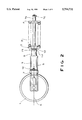
- FIG. 2 is a side view of the device in the tensioned state
- FIG. 3 is an alternative embodiment in the view according to FIG. 1;
- FIG. 4 is the device according to FIG. 3 in the view according to FIG. 2;
- FIG. 5 is the device according to FIG. 4 seen in a section V--V and
- FIG. 6 is the essential parts of a device according to the invention in a side view, seen in a median longitudinal section.
- the tensioning and shock absorption device for an idler wheel 1 of tracked vehicles consists of a mechanical suspension unit with a helical spring 2 and first and second face or backing plates 3, 4, as well as a hydraulic tensioning unit 5.
- the device can be fitted between the mounting plates or elements 6 of the vehicle chassis WC (FIG. 1) and mounting elements 7 of the idler wheel 1 mounted on a wheel support S and rotatable about a wheel axis W which extends perpendicular to a chassis axis A.
- the device is fitted with untensioned spring unit 2, 3 between the mounting elements 7 of the idler wheel and the mounting elements 6 of the vehicle chassis, as can be seen from the lower half of FIG. 1 and the lower half of FIG. 3.
- the spring unit 2, 3, 4 rests with the first backing or first face plate 4 facing away from the idler wheel 1 against parts of the vehicle chassis 6. It can be fixed in this position. In this position takes place a pretensioning of the spring unit by means of hydraulic displacement of the second backing or second face plate 3 by the hydraulic tensioning unit 5, which rests with its plunger 8 or its cylinder 9 against the mounting elements 7 of the idler wheel, which in turn rests against the chain of the vehicle (not shown).
- the plunger 8 advances, the helical spring 2 is pretensioned by the second backing plate. After a corresponding displacement of the backing plate 3, a position is reached wherein it becomes possible to lock the backing plate 3 against back travel.
- a locking element 10 is irretrievably mounted in a suitable manner, which prevents the back travel of the backing plate 3.
- the plunger 8 can then travel back, until the backing plate rests on the locking element 10 and this in turn rests against the mounting part or chassis support WC.
- the cylinder 9 of the hydraulic tensioning unit 5 is affixed to the mounting elements 7 of the running wheel, particularly through welding.
- the hydraulic tensioning unit 5 has a piston 11 with a plunger 8 projecting towards the spring unit 2, 3, 4.
- a feeding device 12 is provided for filling or emptying the chamber 13 containing the hydraulic medium (for instance grease).
- the spring unit consisting of the two backing plates 3, 4 and a helical compression spring 2 is arranged coaxially with the plunger 8 and rests with the first backing plate 4 facing away from the plunger 8 against the mounting elements 6 of the vehicle chassis.
- the backing plate 4 can also be inserted in a corresponding pocket or the like of the mounting frame 6.
- the second plate 3 can rest against the frontal side of the plunger 8, directly or indirectly via a head plate 14 of a bolt 15 guided coaxially through the spring unit.
- the plunger is pushed forward (in the drawing FIG. 1 from the position shown at the bottom to the position shown at the top), whereby the helical compression spring 2 is pretensioned.
- a back stop 10 which rests against the mounting elements 19 of the chassis can be releasably inserted in this position.
- the plunger 8 can then be retracted by slightly emptying the chamber 13, until the position shown in the upper half of FIG. 1 is reached. In this position the device is ready to function.
- a snap ring 16 is arranged to prevent loosing, which when the helical spring 2 is relaxed, can be supported against the rear side of the backing plate 4, but which must not take up any load.
- the bolt 15 serves merely to prevent the spring tensioning unit from bending out and to insure the coaxial arrangement of the backing plates 3 and 4.
- the hydraulic tensioning unit 5 is concentrically surrounded by the spring unit, whereby the second backing plate 3 is affixed to the idler-wheel end of the cylinder 9, particularly is welded thereto, while the backing plate 4 is traversed with motion play by the cylinder 9. It rests against mounting elements 6 of the chassis.
- a plunger 8 can advance towards the mounting elements 7 of the idler wheel 1 and can rest against it.
- a device 12 for filling and emptying the chamber 13 of the cylinder 9 is provided on the side of the piston 9 facing away from the plunger 8 .
- the helical compression spring 2 is coaxially traversed by the cylinder 9. In order to mount the device the position according to the lower half of FIG.
- FIG. 5 various locking elements 10 are shown, which in the embodiment shown on the left in FIG. 5 are insertable in an insertion channel open at the top, this way leading to a blockage of the axial displacement of the backing plate 3, while in the embodiment shown to the right in FIG. 5 the locking element 10 is slid in through a lateral insertion channel formed in the plunger 8.
- the invention offers a device which allows the mounting and dismounting of the device in an untensioned state, whereby preliminary tensioning of the spring tensioning unit and the readiness to operate can be achieved in the simplest manner.
- the tensioning and shock-absorption device for an idler wheel of tracked vehicles consists of a mechanical suspension unit with a helical spring 2 and backing plates 3, 4, as well as a hydraulic tensioning unit 5.
- the hydraulic tensioning unit 5 consists of a plate (7) which can be fastened to a mounting element of the idler wheel, which preferably comprises a device for feeding hydraulic medium into the hydraulic tensioning unit.
- a cylinder 9 of the hydraulic tensioning unit is fastened to this plate 7, for instance by welding.
- a plunger 8 is sealingly guided, while on the outer surface of cylinder 9 a sleeve 20 is sealingly guided, which has a bottom 21 and a collar or flange 22 at the open end.
- This device can be fitted between the mounting element of the vehicle chassis and the mounting elements of the idler wheel.
- the device with untensioned spring unit is inserted, as shown in the lower half of the drawing figure, between the mounting elements of the idler wheel and mounting elements of the vehicle chassis, whereby the corresponding mounting elements of the vehicle chassis is formed by the thereon fastened first backing plate 4.
- the helical spring 2 rests against the first backing plate 4 and against the second backing plate 3.
- the plate 7 is fastened on mounting elements of the idler wheel.
- a pretensioning of the spring unit takes place by means of hydraulic displacement of the second backing plate 3 caused by the hydraulic tensioning unit 5, which rests with its cylinder 9 against mounting elements 7 of the idler wheel, which in turn rests on the vehicle chain.
- the plunger 8 is actuated by pressure, at first the idler wheel is pretensioned against the chain and subsequently the idler wheel in this pretensioned position is used as a countersupport, so that when the plunger is further hydraulically advanced the sleeve 20 and via the collar 22 the backing plate 3 is entrained, whereby the helical spring 2 is pretensioned against the backing plate 4.
- a position is reached wherein it is possible to lock the stop plate 3 against back travel.
- a locking element is inserted between the mounting elements of the chassis and irretrievably mounted in a suitable manner, which prevents the stop plate 3 from back travel.
- the plunger 8 can then be retracted, until the stop plate 3 rests against the corresponding locking element 10, and this in turn rests against a corresponding mounting element.
- a device is made available which allows to mount and dismount the device in an untensioned state, whereby the pretensioning of the spring unit and its readiness to operate can be achieved in the simplest manner. Thereby the overall dimensions of the device are only slightly bigger than the length of the helical compression spring 2 in a relaxed state.
- the invention is not limited to the embodiment examples, but is multiply variable within the framework of the invention.
Landscapes
- Engineering & Computer Science (AREA)
- Chemical & Material Sciences (AREA)
- Combustion & Propulsion (AREA)
- Transportation (AREA)
- Mechanical Engineering (AREA)
- Devices For Conveying Motion By Means Of Endless Flexible Members (AREA)
- Vehicle Body Suspensions (AREA)
- Springs (AREA)
- Handcart (AREA)
- Vehicle Cleaning, Maintenance, Repair, Refitting, And Outriggers (AREA)
Applications Claiming Priority (5)
| Application Number | Priority Date | Filing Date | Title |
|---|---|---|---|
| DE19934323912 DE4323912A1 (de) | 1993-07-16 | 1993-07-16 | Vorrichtung zum Spannen und Abfedern des Leitrades von Kettenfahrzeugen |
| DE4330833.3 | 1993-09-11 | ||
| DE4323912.9 | 1993-09-11 | ||
| DE4330833A DE4330833A1 (de) | 1993-07-16 | 1993-09-11 | Vorrichtung zum Spannen und Abfedern des Leitrades von Kettenfahrzeugen |
| PCT/DE1994/000524 WO1995002533A1 (de) | 1993-07-16 | 1994-05-04 | Vorrichtung zum spannen und abfedern des leitrades von kettenfahrzeugen |
Publications (1)
| Publication Number | Publication Date |
|---|---|
| US5794731A true US5794731A (en) | 1998-08-18 |
Family
ID=25927742
Family Applications (1)
| Application Number | Title | Priority Date | Filing Date |
|---|---|---|---|
| US08/586,646 Expired - Fee Related US5794731A (en) | 1993-07-16 | 1994-05-04 | Tensioning and shock-absorption device for the idler wheel of a tracked vehicle |
Country Status (8)
| Country | Link |
|---|---|
| US (1) | US5794731A (de) |
| EP (1) | EP0707549B1 (de) |
| JP (1) | JP3455880B2 (de) |
| KR (1) | KR100316822B1 (de) |
| AT (1) | ATE160738T1 (de) |
| AU (1) | AU6676194A (de) |
| DE (2) | DE4330833A1 (de) |
| WO (1) | WO1995002533A1 (de) |
Cited By (8)
| Publication number | Priority date | Publication date | Assignee | Title |
|---|---|---|---|---|
| US20040216932A1 (en) * | 2001-07-09 | 2004-11-04 | United Defense, Lp | Hybrid wheel and track vehicle drive system |
| US20060108870A1 (en) * | 2004-11-19 | 2006-05-25 | Livesay Richard E | Idler recoil and adjustment system for track type work machine |
| US20090200862A1 (en) * | 2008-02-11 | 2009-08-13 | Caterpillar Inc. | Idler recoil assembly and machine using same |
| US20110248562A1 (en) * | 2007-05-23 | 2011-10-13 | Giorgio Bordini | Crawler Traction Device |
| US20120305321A1 (en) * | 2009-12-02 | 2012-12-06 | Rolic Invest S.Ar.L. | Snow groomer and relative control method |
| US20140144716A1 (en) * | 2010-06-01 | 2014-05-29 | Joseph J. Wirkus | Crawler track tensioning assembly |
| US10207755B2 (en) | 2016-07-26 | 2019-02-19 | Caterpillar Inc. | Recoil assembly for undercarriage system |
| US20210221454A1 (en) * | 2020-01-17 | 2021-07-22 | Barreto Manufacturing, Inc. | Hydraulic tensioning system for track drive vehicle |
Families Citing this family (2)
| Publication number | Priority date | Publication date | Assignee | Title |
|---|---|---|---|---|
| ATE267112T1 (de) | 1998-04-22 | 2004-06-15 | Intertractor Gmbh | Fahrschiff für raupenfahrzeuge |
| CN105947005A (zh) * | 2016-05-06 | 2016-09-21 | 江苏盖亚环境科技股份有限公司 | 一种土壤取样修复一体钻机的履带涨紧机构 |
Citations (5)
| Publication number | Priority date | Publication date | Assignee | Title |
|---|---|---|---|---|
| US3841715A (en) * | 1972-12-26 | 1974-10-15 | Caterpillar Tractor Co | Idler mounting mechanism and track adjuster |
| US3980351A (en) * | 1975-01-02 | 1976-09-14 | Fiat-Allis Construction Machinery, Inc. | Track idler recoil spring assembly and method for installation and removal |
| US4413862A (en) * | 1980-11-17 | 1983-11-08 | Deere & Company | Track recoil system |
| US4580850A (en) * | 1982-12-30 | 1986-04-08 | Simmel S.P.A. | Safety device for a track stretcher |
| DE4025929A1 (de) * | 1990-08-16 | 1992-02-20 | Intertractor Ag | Spannvorrichtung fuer das leitrad von kettenfahrzeugen |
Family Cites Families (2)
| Publication number | Priority date | Publication date | Assignee | Title |
|---|---|---|---|---|
| US4088377A (en) * | 1976-02-06 | 1978-05-09 | Caterpillar Tractor Co. | Recoil spring lock device |
| DE9011884U1 (de) * | 1990-08-14 | 1990-10-18 | Intertractor AG, 5820 Gevelsberg | Spannvorrichtung für das Leitrad von Kettenfahrzeugen |
-
1993
- 1993-09-11 DE DE4330833A patent/DE4330833A1/de not_active Withdrawn
-
1994
- 1994-05-04 AU AU66761/94A patent/AU6676194A/en not_active Abandoned
- 1994-05-04 WO PCT/DE1994/000524 patent/WO1995002533A1/de not_active Ceased
- 1994-05-04 AT AT94914329T patent/ATE160738T1/de not_active IP Right Cessation
- 1994-05-04 US US08/586,646 patent/US5794731A/en not_active Expired - Fee Related
- 1994-05-04 JP JP50427495A patent/JP3455880B2/ja not_active Expired - Fee Related
- 1994-05-04 DE DE59404735T patent/DE59404735D1/de not_active Expired - Fee Related
- 1994-05-04 EP EP94914329A patent/EP0707549B1/de not_active Expired - Lifetime
- 1994-05-04 KR KR1019960700148A patent/KR100316822B1/ko not_active Expired - Fee Related
Patent Citations (5)
| Publication number | Priority date | Publication date | Assignee | Title |
|---|---|---|---|---|
| US3841715A (en) * | 1972-12-26 | 1974-10-15 | Caterpillar Tractor Co | Idler mounting mechanism and track adjuster |
| US3980351A (en) * | 1975-01-02 | 1976-09-14 | Fiat-Allis Construction Machinery, Inc. | Track idler recoil spring assembly and method for installation and removal |
| US4413862A (en) * | 1980-11-17 | 1983-11-08 | Deere & Company | Track recoil system |
| US4580850A (en) * | 1982-12-30 | 1986-04-08 | Simmel S.P.A. | Safety device for a track stretcher |
| DE4025929A1 (de) * | 1990-08-16 | 1992-02-20 | Intertractor Ag | Spannvorrichtung fuer das leitrad von kettenfahrzeugen |
Cited By (12)
| Publication number | Priority date | Publication date | Assignee | Title |
|---|---|---|---|---|
| US20040216932A1 (en) * | 2001-07-09 | 2004-11-04 | United Defense, Lp | Hybrid wheel and track vehicle drive system |
| US20060108870A1 (en) * | 2004-11-19 | 2006-05-25 | Livesay Richard E | Idler recoil and adjustment system for track type work machine |
| US7252349B2 (en) * | 2004-11-19 | 2007-08-07 | Caterpillar Inc | Idler recoil and adjustment system for track type work machine |
| US20110248562A1 (en) * | 2007-05-23 | 2011-10-13 | Giorgio Bordini | Crawler Traction Device |
| US20090200862A1 (en) * | 2008-02-11 | 2009-08-13 | Caterpillar Inc. | Idler recoil assembly and machine using same |
| US8011740B2 (en) | 2008-02-11 | 2011-09-06 | Caterpillar Inc. | Idler recoil assembly and machine using same |
| US20120305321A1 (en) * | 2009-12-02 | 2012-12-06 | Rolic Invest S.Ar.L. | Snow groomer and relative control method |
| US8579057B2 (en) * | 2009-12-02 | 2013-11-12 | Snowgrolic S.Ar.L. | Snow groomer and relative control method |
| US20140144716A1 (en) * | 2010-06-01 | 2014-05-29 | Joseph J. Wirkus | Crawler track tensioning assembly |
| US10207755B2 (en) | 2016-07-26 | 2019-02-19 | Caterpillar Inc. | Recoil assembly for undercarriage system |
| US20210221454A1 (en) * | 2020-01-17 | 2021-07-22 | Barreto Manufacturing, Inc. | Hydraulic tensioning system for track drive vehicle |
| US12030568B2 (en) * | 2020-01-17 | 2024-07-09 | Barreto Manufacturing, Inc. | Hydraulic tensioning system for track drive vehicle |
Also Published As
| Publication number | Publication date |
|---|---|
| EP0707549A1 (de) | 1996-04-24 |
| DE4330833A1 (de) | 1995-03-23 |
| AU6676194A (en) | 1995-02-13 |
| WO1995002533A1 (de) | 1995-01-26 |
| ATE160738T1 (de) | 1997-12-15 |
| JP3455880B2 (ja) | 2003-10-14 |
| EP0707549B1 (de) | 1997-12-03 |
| KR100316822B1 (ko) | 2002-02-28 |
| JPH09500070A (ja) | 1997-01-07 |
| DE59404735D1 (de) | 1998-01-15 |
Similar Documents
| Publication | Publication Date | Title |
|---|---|---|
| US5794731A (en) | Tensioning and shock-absorption device for the idler wheel of a tracked vehicle | |
| US5857822A (en) | Ejection and compacting system for refuse truck | |
| US4992019A (en) | Rubbish collection vehicle | |
| DE3025269C2 (de) | ||
| DE102005004136B4 (de) | Halteeinrichtung für bewegliche Giessform sowie Formschließeinheit | |
| US2934226A (en) | Compaction bodies | |
| EP1054821A1 (de) | Handhabungssystem für müllbehälter | |
| CN215849824U (zh) | 一种核电放射性固体废物、废树脂压实减容的超压机 | |
| US3980351A (en) | Track idler recoil spring assembly and method for installation and removal | |
| US9469279B2 (en) | Support for supporting and compensating a shift in the position of a parked semi-trailer | |
| CN111169824B (zh) | 粉粒物料运输车料盖及粉粒物料运输车 | |
| US3687313A (en) | Plunger shield for refuse vehicle loading chamber | |
| US20030215315A1 (en) | Front-loading refuse body with ejection wall | |
| US4625660A (en) | Auxiliary apparatus for discharging incineration residues of furnaces, particularly refuse incinerators | |
| US9358745B2 (en) | Compactor | |
| US3207336A (en) | Refuse compacting vehicle body | |
| CN209739909U (zh) | 滑块可调的压缩垃圾车推铲 | |
| CN218536840U (zh) | 一种自卸车防侧翻安全装置 | |
| US4027584A (en) | Water actuated garbage compactor | |
| US5809875A (en) | Apparatus for crushing scrap vehicle wheels | |
| US3237967A (en) | Transport container manipulating apparatus for vehicles | |
| US6623153B2 (en) | Device and method for charging a plasticizing unit of an injection molding machine | |
| CN210848248U (zh) | 一种金属压射装置 | |
| CN216580761U (zh) | 履带行走底盘和工程机械 | |
| CN110482047A (zh) | 一种可车载移动倾翻式密封罐装置 |
Legal Events
| Date | Code | Title | Description |
|---|---|---|---|
| AS | Assignment |
Owner name: INTERTRACTOR AG, GERMANY Free format text: ASSIGNMENT OF ASSIGNORS INTEREST;ASSIGNOR:KLAUS, HELMUT;REEL/FRAME:008010/0588 Effective date: 19951218 |
|
| FEPP | Fee payment procedure |
Free format text: PAYOR NUMBER ASSIGNED (ORIGINAL EVENT CODE: ASPN); ENTITY STATUS OF PATENT OWNER: LARGE ENTITY |
|
| FPAY | Fee payment |
Year of fee payment: 4 |
|
| REMI | Maintenance fee reminder mailed | ||
| LAPS | Lapse for failure to pay maintenance fees | ||
| STCH | Information on status: patent discontinuation |
Free format text: PATENT EXPIRED DUE TO NONPAYMENT OF MAINTENANCE FEES UNDER 37 CFR 1.362 |
|
| FP | Lapsed due to failure to pay maintenance fee |
Effective date: 20060818 |