US5827152A - Control system for automtic transmission for vehicle - Google Patents
Control system for automtic transmission for vehicle Download PDFInfo
- Publication number
- US5827152A US5827152A US08/970,538 US97053897A US5827152A US 5827152 A US5827152 A US 5827152A US 97053897 A US97053897 A US 97053897A US 5827152 A US5827152 A US 5827152A
- Authority
- US
- United States
- Prior art keywords
- hydraulically engaged
- hydraulically
- engaged element
- shift
- slipping
- Prior art date
- Legal status (The legal status is an assumption and is not a legal conclusion. Google has not performed a legal analysis and makes no representation as to the accuracy of the status listed.)
- Expired - Lifetime
Links
Images


Classifications
-
- F—MECHANICAL ENGINEERING; LIGHTING; HEATING; WEAPONS; BLASTING
- F16—ENGINEERING ELEMENTS AND UNITS; GENERAL MEASURES FOR PRODUCING AND MAINTAINING EFFECTIVE FUNCTIONING OF MACHINES OR INSTALLATIONS; THERMAL INSULATION IN GENERAL
- F16H—GEARING
- F16H61/00—Control functions within control units of change-speed- or reversing-gearings for conveying rotary motion ; Control of exclusively fluid gearing, friction gearing, gearings with endless flexible members or other particular types of gearing
- F16H61/02—Control functions within control units of change-speed- or reversing-gearings for conveying rotary motion ; Control of exclusively fluid gearing, friction gearing, gearings with endless flexible members or other particular types of gearing characterised by the signals used
- F16H61/0202—Control functions within control units of change-speed- or reversing-gearings for conveying rotary motion ; Control of exclusively fluid gearing, friction gearing, gearings with endless flexible members or other particular types of gearing characterised by the signals used the signals being electric
- F16H61/0204—Control functions within control units of change-speed- or reversing-gearings for conveying rotary motion ; Control of exclusively fluid gearing, friction gearing, gearings with endless flexible members or other particular types of gearing characterised by the signals used the signals being electric for gearshift control, e.g. control functions for performing shifting or generation of shift signal
- F16H61/0206—Layout of electro-hydraulic control circuits, e.g. arrangement of valves
-
- F—MECHANICAL ENGINEERING; LIGHTING; HEATING; WEAPONS; BLASTING
- F16—ENGINEERING ELEMENTS AND UNITS; GENERAL MEASURES FOR PRODUCING AND MAINTAINING EFFECTIVE FUNCTIONING OF MACHINES OR INSTALLATIONS; THERMAL INSULATION IN GENERAL
- F16H—GEARING
- F16H59/00—Control inputs to control units of change-speed- or reversing-gearings for conveying rotary motion
- F16H59/36—Inputs being a function of speed
- F16H59/46—Inputs being a function of speed dependent on a comparison between speeds
-
- B—PERFORMING OPERATIONS; TRANSPORTING
- B60—VEHICLES IN GENERAL
- B60W—CONJOINT CONTROL OF VEHICLE SUB-UNITS OF DIFFERENT TYPE OR DIFFERENT FUNCTION; CONTROL SYSTEMS SPECIALLY ADAPTED FOR HYBRID VEHICLES; ROAD VEHICLE DRIVE CONTROL SYSTEMS FOR PURPOSES NOT RELATED TO THE CONTROL OF A PARTICULAR SUB-UNIT
- B60W2510/00—Input parameters relating to a particular sub-units
- B60W2510/02—Clutches
- B60W2510/0241—Clutch slip, i.e. difference between input and output speeds
-
- Y—GENERAL TAGGING OF NEW TECHNOLOGICAL DEVELOPMENTS; GENERAL TAGGING OF CROSS-SECTIONAL TECHNOLOGIES SPANNING OVER SEVERAL SECTIONS OF THE IPC; TECHNICAL SUBJECTS COVERED BY FORMER USPC CROSS-REFERENCE ART COLLECTIONS [XRACs] AND DIGESTS
- Y10—TECHNICAL SUBJECTS COVERED BY FORMER USPC
- Y10S—TECHNICAL SUBJECTS COVERED BY FORMER USPC CROSS-REFERENCE ART COLLECTIONS [XRACs] AND DIGESTS
- Y10S477/00—Interrelated power delivery controls, including engine control
- Y10S477/906—Means detecting or ameliorating the effects of malfunction or potential malfunction
Definitions
- the present invention relates to a control system for an automatic transmission for a vehicle, which performs a shifting by selectively bringing any of a plurality of hydraulically engaged elements into an engaged state, based upon the operational state of the vehicle.
- the hydraulic pressure for bringing a hydraulic clutch or a hydraulic brake, in the automatic transmission of a vehicle, into its engaged state is set at the minimum pressure (i.e., at a skeleton pressure) so as to reduce shifting shock.
- the minimum pressure i.e., at a skeleton pressure
- a control system for an automatic transmission for a vehicle disclosed in Japanese Patent Application Laid-Open No. 300457/92 is designed such that when slipping of the hydraulic clutch or the hydraulic brake is detected, the hydraulic pressure supplied to the hydraulic clutch or the hydraulic brake is increased to inhibit the slipping.
- the present invention has been accomplished with such circumstance in view, and it is an object of the present invention to reliably prevent the slipping of hydraulically engaged elements without increasing the hydraulic pressure.
- a control system for an automatic transmission for a vehicle which performs shifting by selectively bringing any of a plurality of hydraulically engaged elements into an engaged state, based upon an operational state of the vehicle.
- the control system comprises a slip detecting means for detecting slipping of a selected hydraulically engaged element during non-shifting; a determining means for determining one of the hydraulically engaged elements which has a driving force transmitting capacity larger than the selected hydraulically engaged element; and a switching means for switching the selected hydraulically engaged element to the hydraulically engaged element determined by the determining means to thereby bring the determined hydraulically engaged element into its engaged state, when slipping is detected by the slip detecting means.
- the determining means determines one of the hydraulically engaged elements for establishing a shift stage lower than a shift stage established by the selected hydraulically engaged element.
- the hydraulically engaged element selected based on the operational state of the vehicle corresponds with the hydraulically engaged element determined by said determining means
- the hydraulically engaged element selected based on the operational state of the vehicle is brought into its engaged state, in place of the hydraulically engaged element determined by the determining means.
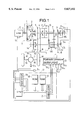
- FIG. 1 is an illustration of the arrangement of an automatic transmission and a control unit therefor.
- FIG. 2 is a flow chart of the operation of the preferred embodiment of the present invention.
- FIG. 3 is a flow chart of a portion of the operation of the preferred embodiment.
- FIG. 4 is a graph for explaining the operation.
- the automatic transmission T for a vehicle includes a main shaft MS connected to a crankshaft 1 of an engine E through a torque converter 2 having a lock-up clutch L, and a counter shaft CS connected to the main shaft MS through a plurality of gear trains.
- Carried on the main shaft MS are a main first-shift gear 3, a main second-shift gear 4, a main third-shift gear 5, a main fourth-shift gear 6 and a main reverse gear 7.
- Carried on the counter shaft CS are a counter first-shift gear 8 meshed with the main first-shift gear 3, a counter second-shift gear 9 meshed with the main second-shift gear 4, a counter third-shift gear 10 meshed with the main third-shift gear 5, a counter fourth-shift gear 11 meshed with the main fourth-shift gear 6 and a counter reverse gear 12 connected to the main reverse gear 7 through a reverse idle gear 13.
- first-shift stage is established.
- the first-shift clutch C 1 is maintained in an engaged state even during establishment of second to fourth shift stages and hence, the counter first-shift gear 8 is supported through a one-way clutch C OW .
- main second-shift gear 4 relatively rotatably carried on the main shaft MS is coupled to the main shaft MS by a second-shift clutch C 2
- a second-shift stage is established.
- the counter third-shift gear 10 relatively rotatably carried on the counter shaft CS is coupled to the counter shaft CS by a third-shift clutch C 3 , a third-shift stage is established.
- main fourth-shift gear 6 relatively rotatably carried on the main shaft MS is coupled to the main shaft MS by a fourth-shift reverse clutch C 4R in a condition in which the counter fourth-shift gear 11 relatively rotatably carried on the counter shaft CS has been coupled to the counter shaft CS by a selector gear SG
- a fourth-shift stage is established.
- the counter reverse gear 7 relatively rotatably carried on the main shaft MS is coupled to the main shaft MS by the fourth-shift reverse clutch C 4R in a condition in which the counter reverse gear 12 relatively rotatably carried on the counter shaft CS has been coupled to the counter shaft CS by the selector gear SG.
- the rotation of the counter shaft CS is transmitted through a final drive gear 14 and a final driven gear 15 to a differential D and then transmitted therefrom through left and right axles 16, 16 to driving wheels W, W.
- An electronic control unit U includes a CPU 17, a ROM 18, a RAM 19, an input circuit 20 and an output circuit 21.
- Inputted to the input circuit 20 of the electronic control unit U are a throttle opening degree TH detected by a throttle opening degree sensor S 1 mounted on the engine E, a main shaft revolution-number N MS detected by a main shaft revolution-number sensor S 2 mounted on the main shaft MS, a counter shaft revolution-number N CS detected by a counter shaft revolution-number sensor S 3 mounted on the counter shaft CS, a vehicle speed V detected by a vehicle speed sensor S 4 mounted on the differential D, and a shift selecting lever position S detected by a shift selecting lever position sensor S 5 .
- the output circuit 21 of the electronic control unit U is connected to the shift solenoids SL 1 and SL 2 , lock-up clutch solenoids SL 3 and SL 4 and a shifting clutch hydraulic pressure solenoid SL 5 provided in a hydraulic pressure control circuit O, in order to control the operation of the first-shift clutch C 1 , the second-shift clutch C 2 , the third-shift clutch C 3 , the fourth-shift reverse clutch C 4R , the selector gear SG and the lock-up clutch L of the automatic transmission T.
- a timer is started at Step S7 if all of the following conditions (1) to (6) are established: (1) the position of a shift selecting lever of the automatic transmission T is in a "D4" range or a "D3" range which are automatic shifting ranges, at Step S1 of a flow chart in FIG.
- the currently established shift stage is a second shift stage, a third shift stage or a fourth shift stage, at Step S2; (3) a throttle opening degree TH detected by the throttle opening degree sensor S 1 , is between a fully-closed opening degree CTH and a control region opening degree TH1, at Step S3; (4) a vehicle speed V detected by the vehicle speed sensor S 4 , is not less than a reference vehicle speed V 1 , at Step S4; (5) the automatic transmission T is not shifting, at Step S5; and (6) a clutch slip rate ECL is smaller than a reference slip rate E1 at Step S6. If any of the conditions at Steps S1 to S6 is not established, the timer is reset at Step S8.
- a clutch slip rate ECL is calculated according to an equation of:
- the clutch slip rate ECL is 1.
- the clutch slips resulting in an increased number N MS of revolutions of the main shaft, the value of the clutch slip rate ECL becomes less than 1. If the clutch slip rate ECL becomes less than the reference slip rate E1 by comparing the clutch slip rate ECL with the reference slip rate E 1 (E 1 ⁇ 1), it is determined that the clutch has been brought into a slipping state.
- the shift stage Sx is shifted down to a shift stage lower by one stage than a current shift stage S 0 at Step S10, and a control flag F CS indicating the fact that a slip-avoiding control is being carried out, is set at "1" at Step S11. Therefore, if slipping is generated in the clutch during traveling of the vehicle at the fourth-shift stage, the fourth-shift stage is shifted down to the third-shift stage. If slipping is generated in the clutch during traveling of the vehicle at the second-shift stage, the second-shift stage is shifted down to the first-shift stage.
- the substantial capacity (transmittable torque) of the clutch for a lower-shift stage used at higher engine output during starting or accelerating of the vehicle is set at a larger value. Therefore, if the shift stage is shifted down to a lower shift stage when the clutch is slipping, the slipping of the clutch can be prevented and reduced. Even when there is no difference between the substantial capacity of the clutch before shifting and the substantial capacity of the clutch after shifting, the relationship between the throttle opening degree TH and the vehicle speed V is varied by the shift change, and the clutch operation can move out of a slip-generating zone.
- Step S24 the shift stage Sx provided after the down-shifting is maintained until it corresponds with a shift stage S MAP searched from the usual shift map.
- the control flag F CS is reset at "0" at Step S25. As a result, the slip-avoiding control is finished, returning to a shift control based on the usual shift map.
- the shift stage is shifted down to a lower shift stage when slipping is generated in the clutch.
- the shift stage can be shifted up to a higher shift stage.
- the hydraulically engaged element of the automatic transmission in the embodiment is not limited to the clutch, and may be a brake.
- the determining means determines the hydraulically engaged element for establishing a shift stage lower than the shift stage established by the hydraulically engaged element which is in its engaged state. Therefore, it is possible to further reliably prevent the slipping.
Landscapes
- Engineering & Computer Science (AREA)
- General Engineering & Computer Science (AREA)
- Mechanical Engineering (AREA)
- Control Of Transmission Device (AREA)
Priority Applications (1)
| Application Number | Priority Date | Filing Date | Title |
|---|---|---|---|
| US08/970,538 US5827152A (en) | 1994-08-23 | 1997-11-14 | Control system for automtic transmission for vehicle |
Applications Claiming Priority (4)
| Application Number | Priority Date | Filing Date | Title |
|---|---|---|---|
| JP6198136A JP2967392B2 (ja) | 1994-08-23 | 1994-08-23 | 車両用自動変速機の制御装置 |
| JP6-198136 | 1994-08-23 | ||
| US51563995A | 1995-08-16 | 1995-08-16 | |
| US08/970,538 US5827152A (en) | 1994-08-23 | 1997-11-14 | Control system for automtic transmission for vehicle |
Related Parent Applications (1)
| Application Number | Title | Priority Date | Filing Date |
|---|---|---|---|
| US51563995A Continuation | 1994-08-23 | 1995-08-16 |
Publications (1)
| Publication Number | Publication Date |
|---|---|
| US5827152A true US5827152A (en) | 1998-10-27 |
Family
ID=16386052
Family Applications (1)
| Application Number | Title | Priority Date | Filing Date |
|---|---|---|---|
| US08/970,538 Expired - Lifetime US5827152A (en) | 1994-08-23 | 1997-11-14 | Control system for automtic transmission for vehicle |
Country Status (4)
| Country | Link |
|---|---|
| US (1) | US5827152A (de) |
| EP (1) | EP0698754B1 (de) |
| JP (1) | JP2967392B2 (de) |
| DE (1) | DE69520990T2 (de) |
Cited By (1)
| Publication number | Priority date | Publication date | Assignee | Title |
|---|---|---|---|---|
| US20080182715A1 (en) * | 2006-12-29 | 2008-07-31 | Mike Dickinson | Automotive-transmission clutch-pressure duration |
Citations (9)
| Publication number | Priority date | Publication date | Assignee | Title |
|---|---|---|---|---|
| US4785689A (en) * | 1985-12-24 | 1988-11-22 | Toyota Jidosha Kabushiki Kaisha | Failsafe system in automatic transmission |
| EP0310277A2 (de) * | 1987-09-28 | 1989-04-05 | SATURN CORPORATION (a Delaware corp.) | Erfassen und Ausregeln des Rutsches bei stationärem Lauf für ein Getriebe eines Kraftfahrzeugs |
| US4843551A (en) * | 1987-09-28 | 1989-06-27 | Saturn Corporation | Failure mode shift pattern alteration for an electronically controlled transmission |
| US4845621A (en) * | 1986-08-19 | 1989-07-04 | Aisin Seiki Kabushiki Kaisha | Speed control apparatus |
| EP0353771A2 (de) * | 1988-08-05 | 1990-02-07 | Honda Giken Kogyo Kabushiki Kaisha | Gerät zur Gangschaltungssteuerung in einem automatischen Getriebe |
| US4958538A (en) * | 1987-08-10 | 1990-09-25 | Suzuki Jidosha Kogyo Kabushiki | Method and apparatus for controlling line pressure of continuously variable transmission system |
| EP0457585A2 (de) * | 1990-05-18 | 1991-11-21 | Toyota Jidosha Kabushiki Kaisha | System und Verfahren zur Regelung eines automatischen Getriebes |
| JPH04300457A (ja) * | 1991-03-27 | 1992-10-23 | Jatco Corp | 自動変速機の変速制御装置 |
| US5400678A (en) * | 1992-10-30 | 1995-03-28 | Ford Motor Company | Line pressure optimization in an automatic transmission |
-
1994
- 1994-08-23 JP JP6198136A patent/JP2967392B2/ja not_active Expired - Fee Related
-
1995
- 1995-08-21 EP EP95305797A patent/EP0698754B1/de not_active Expired - Lifetime
- 1995-08-21 DE DE69520990T patent/DE69520990T2/de not_active Expired - Fee Related
-
1997
- 1997-11-14 US US08/970,538 patent/US5827152A/en not_active Expired - Lifetime
Patent Citations (9)
| Publication number | Priority date | Publication date | Assignee | Title |
|---|---|---|---|---|
| US4785689A (en) * | 1985-12-24 | 1988-11-22 | Toyota Jidosha Kabushiki Kaisha | Failsafe system in automatic transmission |
| US4845621A (en) * | 1986-08-19 | 1989-07-04 | Aisin Seiki Kabushiki Kaisha | Speed control apparatus |
| US4958538A (en) * | 1987-08-10 | 1990-09-25 | Suzuki Jidosha Kogyo Kabushiki | Method and apparatus for controlling line pressure of continuously variable transmission system |
| EP0310277A2 (de) * | 1987-09-28 | 1989-04-05 | SATURN CORPORATION (a Delaware corp.) | Erfassen und Ausregeln des Rutsches bei stationärem Lauf für ein Getriebe eines Kraftfahrzeugs |
| US4843551A (en) * | 1987-09-28 | 1989-06-27 | Saturn Corporation | Failure mode shift pattern alteration for an electronically controlled transmission |
| EP0353771A2 (de) * | 1988-08-05 | 1990-02-07 | Honda Giken Kogyo Kabushiki Kaisha | Gerät zur Gangschaltungssteuerung in einem automatischen Getriebe |
| EP0457585A2 (de) * | 1990-05-18 | 1991-11-21 | Toyota Jidosha Kabushiki Kaisha | System und Verfahren zur Regelung eines automatischen Getriebes |
| JPH04300457A (ja) * | 1991-03-27 | 1992-10-23 | Jatco Corp | 自動変速機の変速制御装置 |
| US5400678A (en) * | 1992-10-30 | 1995-03-28 | Ford Motor Company | Line pressure optimization in an automatic transmission |
Cited By (1)
| Publication number | Priority date | Publication date | Assignee | Title |
|---|---|---|---|---|
| US20080182715A1 (en) * | 2006-12-29 | 2008-07-31 | Mike Dickinson | Automotive-transmission clutch-pressure duration |
Also Published As
| Publication number | Publication date |
|---|---|
| EP0698754A3 (de) | 1997-05-14 |
| JPH0861476A (ja) | 1996-03-08 |
| EP0698754B1 (de) | 2001-05-23 |
| JP2967392B2 (ja) | 1999-10-25 |
| DE69520990T2 (de) | 2001-09-06 |
| DE69520990D1 (de) | 2001-06-28 |
| EP0698754A2 (de) | 1996-02-28 |
Similar Documents
| Publication | Publication Date | Title |
|---|---|---|
| US5738607A (en) | Control system for automatic transmission for vehicle | |
| US4911275A (en) | System for controlling a clutch for a vehicle | |
| EP0240283A2 (de) | Steuersystem für eine Kraftfahrzeugkupplung | |
| US6603214B1 (en) | Control equipment for a vehicle and control method thereof | |
| RU2338099C2 (ru) | Способ предотвращения рывков, связанных с переключением режимов в автомобиле | |
| US7762925B2 (en) | Engine power reduction during automatic transmission shifting | |
| EP0725234B1 (de) | Steuerungssystem für automatisches Fahrzeuggetriebe | |
| US5209332A (en) | Control system for a clutch of a motor vehicle | |
| EP1400732A2 (de) | Steuersystem und -verfahren für Automatikgetriebe | |
| JP3007547B2 (ja) | 車両用油圧作動式変速機の油圧制御装置 | |
| US5827152A (en) | Control system for automtic transmission for vehicle | |
| US5669848A (en) | Control system for automatic transmission for vehicle | |
| JP4007321B2 (ja) | 自動車の制御装置 | |
| JP3266751B2 (ja) | 車両用自動変速機の制御装置 | |
| JPH1047463A (ja) | 自動変速機のダウンシフト制御装置及びその方法 | |
| JP2899935B2 (ja) | 車両用油圧作動式変速機の制御装置 | |
| JPH08303575A (ja) | 自動変速機 | |
| JP3295300B2 (ja) | 車両用自動変速機の制御装置 | |
| JP3622355B2 (ja) | 自動変速機の制御装置 | |
| JP3426380B2 (ja) | 車両用自動変速機の制御装置 | |
| JP3223232B2 (ja) | 車両用自動変速機の制御装置 | |
| KR100716626B1 (ko) | 자동 변속 차량용 더블 클러치 구동방법 | |
| JPH06313477A (ja) | 車両用自動変速機装置 | |
| JPH07127720A (ja) | 車両用自動変速機の変速制御装置 | |
| JP2000018379A (ja) | 自動変速機の制御方法 |
Legal Events
| Date | Code | Title | Description |
|---|---|---|---|
| STCF | Information on status: patent grant |
Free format text: PATENTED CASE |
|
| FEPP | Fee payment procedure |
Free format text: PAYOR NUMBER ASSIGNED (ORIGINAL EVENT CODE: ASPN); ENTITY STATUS OF PATENT OWNER: LARGE ENTITY |
|
| CC | Certificate of correction | ||
| FPAY | Fee payment |
Year of fee payment: 4 |
|
| FPAY | Fee payment |
Year of fee payment: 8 |
|
| FPAY | Fee payment |
Year of fee payment: 12 |