US5854874A - Image recording/reproducing system - Google Patents
Image recording/reproducing system Download PDFInfo
- Publication number
- US5854874A US5854874A US08/717,235 US71723596A US5854874A US 5854874 A US5854874 A US 5854874A US 71723596 A US71723596 A US 71723596A US 5854874 A US5854874 A US 5854874A
- Authority
- US
- United States
- Prior art keywords
- semiconductor chip
- external housing
- housing
- reproducing system
- digital information
- Prior art date
- Legal status (The legal status is an assumption and is not a legal conclusion. Google has not performed a legal analysis and makes no representation as to the accuracy of the status listed.)
- Expired - Fee Related
Links
- 229910052782 aluminium Inorganic materials 0.000 claims abstract description 9
- XAGFODPZIPBFFR-UHFFFAOYSA-N aluminium Chemical compound [Al] XAGFODPZIPBFFR-UHFFFAOYSA-N 0.000 claims abstract description 9
- RYGMFSIKBFXOCR-UHFFFAOYSA-N Copper Chemical compound [Cu] RYGMFSIKBFXOCR-UHFFFAOYSA-N 0.000 claims abstract description 8
- 229910052802 copper Inorganic materials 0.000 claims abstract description 8
- 239000010949 copper Substances 0.000 claims abstract description 8
- 239000004065 semiconductor Substances 0.000 claims description 54
- 238000012545 processing Methods 0.000 claims description 15
- 230000003287 optical effect Effects 0.000 claims description 11
- 230000004888 barrier function Effects 0.000 claims description 9
- 238000012546 transfer Methods 0.000 claims description 9
- 238000002955 isolation Methods 0.000 claims description 7
- 230000005540 biological transmission Effects 0.000 claims description 6
- 239000006260 foam Substances 0.000 claims description 4
- FYYHWMGAXLPEAU-UHFFFAOYSA-N Magnesium Chemical compound [Mg] FYYHWMGAXLPEAU-UHFFFAOYSA-N 0.000 claims description 3
- BQCADISMDOOEFD-UHFFFAOYSA-N Silver Chemical compound [Ag] BQCADISMDOOEFD-UHFFFAOYSA-N 0.000 claims description 3
- PCHJSUWPFVWCPO-UHFFFAOYSA-N gold Chemical compound [Au] PCHJSUWPFVWCPO-UHFFFAOYSA-N 0.000 claims description 3
- 229910052737 gold Inorganic materials 0.000 claims description 3
- 239000010931 gold Substances 0.000 claims description 3
- 229910052749 magnesium Inorganic materials 0.000 claims description 3
- 239000011777 magnesium Substances 0.000 claims description 3
- 229910052709 silver Inorganic materials 0.000 claims description 3
- 239000004332 silver Substances 0.000 claims description 3
- 230000017525 heat dissipation Effects 0.000 claims 10
- 230000003467 diminishing effect Effects 0.000 claims 2
- 229910052751 metal Inorganic materials 0.000 claims 2
- 239000002184 metal Substances 0.000 claims 2
- 239000000463 material Substances 0.000 abstract description 8
- 230000003292 diminished effect Effects 0.000 abstract description 4
- 239000003570 air Substances 0.000 description 11
- 230000009467 reduction Effects 0.000 description 11
- 230000007246 mechanism Effects 0.000 description 10
- 239000004973 liquid crystal related substance Substances 0.000 description 6
- 239000004020 conductor Substances 0.000 description 5
- 230000008901 benefit Effects 0.000 description 4
- 238000010586 diagram Methods 0.000 description 4
- 230000004048 modification Effects 0.000 description 3
- 238000012986 modification Methods 0.000 description 3
- 239000012080 ambient air Substances 0.000 description 2
- 230000000694 effects Effects 0.000 description 2
- 238000000034 method Methods 0.000 description 2
- 230000005855 radiation Effects 0.000 description 2
- 239000000758 substrate Substances 0.000 description 2
- XUIMIQQOPSSXEZ-UHFFFAOYSA-N Silicon Chemical compound [Si] XUIMIQQOPSSXEZ-UHFFFAOYSA-N 0.000 description 1
- 230000006835 compression Effects 0.000 description 1
- 238000007906 compression Methods 0.000 description 1
- 238000013461 design Methods 0.000 description 1
- 230000020169 heat generation Effects 0.000 description 1
- 230000001771 impaired effect Effects 0.000 description 1
- 230000006872 improvement Effects 0.000 description 1
- 239000007769 metal material Substances 0.000 description 1
- 239000004033 plastic Substances 0.000 description 1
- 230000036544 posture Effects 0.000 description 1
- 230000008569 process Effects 0.000 description 1
- 238000005204 segregation Methods 0.000 description 1
- 229910052710 silicon Inorganic materials 0.000 description 1
- 239000010703 silicon Substances 0.000 description 1
- 230000001629 suppression Effects 0.000 description 1
- 230000009466 transformation Effects 0.000 description 1
Images


Classifications
-
- G—PHYSICS
- G11—INFORMATION STORAGE
- G11B—INFORMATION STORAGE BASED ON RELATIVE MOVEMENT BETWEEN RECORD CARRIER AND TRANSDUCER
- G11B33/00—Constructional parts, details or accessories not provided for in the other groups of this subclass
- G11B33/12—Disposition of constructional parts in the apparatus, e.g. of power supply, of modules
- G11B33/121—Disposition of constructional parts in the apparatus, e.g. of power supply, of modules the apparatus comprising a single recording/reproducing device
-
- H—ELECTRICITY
- H04—ELECTRIC COMMUNICATION TECHNIQUE
- H04N—PICTORIAL COMMUNICATION, e.g. TELEVISION
- H04N5/00—Details of television systems
- H04N5/222—Studio circuitry; Studio devices; Studio equipment
-
- G—PHYSICS
- G11—INFORMATION STORAGE
- G11B—INFORMATION STORAGE BASED ON RELATIVE MOVEMENT BETWEEN RECORD CARRIER AND TRANSDUCER
- G11B31/00—Arrangements for the associated working of recording or reproducing apparatus with related apparatus
- G11B31/006—Arrangements for the associated working of recording or reproducing apparatus with related apparatus with video camera or receiver
-
- G—PHYSICS
- G11—INFORMATION STORAGE
- G11B—INFORMATION STORAGE BASED ON RELATIVE MOVEMENT BETWEEN RECORD CARRIER AND TRANSDUCER
- G11B33/00—Constructional parts, details or accessories not provided for in the other groups of this subclass
- G11B33/14—Reducing influence of physical parameters, e.g. temperature change, moisture, dust
- G11B33/1406—Reducing the influence of the temperature
- G11B33/1426—Reducing the influence of the temperature by cooling plates, e.g. fins
-
- H—ELECTRICITY
- H04—ELECTRIC COMMUNICATION TECHNIQUE
- H04N—PICTORIAL COMMUNICATION, e.g. TELEVISION
- H04N23/00—Cameras or camera modules comprising electronic image sensors; Control thereof
- H04N23/50—Constructional details
- H04N23/52—Elements optimising image sensor operation, e.g. for electromagnetic interference [EMI] protection or temperature control by heat transfer or cooling elements
-
- H—ELECTRICITY
- H04—ELECTRIC COMMUNICATION TECHNIQUE
- H04N—PICTORIAL COMMUNICATION, e.g. TELEVISION
- H04N5/00—Details of television systems
- H04N5/76—Television signal recording
-
- H—ELECTRICITY
- H04—ELECTRIC COMMUNICATION TECHNIQUE
- H04N—PICTORIAL COMMUNICATION, e.g. TELEVISION
- H04N5/00—Details of television systems
- H04N5/76—Television signal recording
- H04N5/765—Interface circuits between an apparatus for recording and another apparatus
- H04N5/77—Interface circuits between an apparatus for recording and another apparatus between a recording apparatus and a television camera
- H04N5/772—Interface circuits between an apparatus for recording and another apparatus between a recording apparatus and a television camera the recording apparatus and the television camera being placed in the same enclosure
-
- G—PHYSICS
- G11—INFORMATION STORAGE
- G11B—INFORMATION STORAGE BASED ON RELATIVE MOVEMENT BETWEEN RECORD CARRIER AND TRANSDUCER
- G11B33/00—Constructional parts, details or accessories not provided for in the other groups of this subclass
- G11B33/02—Cabinets; Cases; Stands; Disposition of apparatus therein or thereon
- G11B33/08—Insulation or absorption of undesired vibrations or sounds
-
- H—ELECTRICITY
- H04—ELECTRIC COMMUNICATION TECHNIQUE
- H04N—PICTORIAL COMMUNICATION, e.g. TELEVISION
- H04N5/00—Details of television systems
- H04N5/76—Television signal recording
- H04N5/78—Television signal recording using magnetic recording
- H04N5/781—Television signal recording using magnetic recording on disks or drums
Definitions
- the present invention relates to a video camera or still camera or combined video/still camera for recording a digital signal.
- the invention is concerned with how to reduce a size of a camera system which adopts a PC card type magnetic recording medium.
- a digital signal compressing circuit or an LSI thereof involves a heat generation of several watts or so. According to the related art, therefore, when such circuit is mounted within an image recording/reproducing system, there arises a problem that the smaller the size of the camera, the internal temperature of the system becomes higher.
- a magnetic recording arrangement using a hard disk is apt to be affected by any impact or vibration in comparison with a magnetic recording arrangement using an ordinary magnetic tape.
- Objects of the present invention are to minimize a rise in internal temperature of an image recording/reproducing system, protect a hard disk against an impact exerted on an exterior of the system, and protect the hard disk from heat generated by a signal processing circuit while reducing a size of the recording/reproducing system.
- a magnetic recording arrangement comprising a hard disk and a digital signal compressing circuit on opposite surfaces, i.e., a front and back, of a single circuit board, disposing the hard disk centrally in an interior of the image recording/reproducing system, disposing the signal compressing circuit in the vicinity of (i.e., in close proximity to) the system housing, and interposing a heat radiating plate or material between the package surface of an LSI (Large Scale Integrated) package of the signal compressing circuit and the system housing.
- LSI Large Scale Integrated
- a magnetic recording arrangement comprising a hard disk and a digital signal compressing circuit are disposed on opposite front and back surfaces of a single circuit board, whereby a digital signal recording circuit can be constructed having a small volume, and the circuit board can act as a thermal barrier to reduce or block a heat conduction path from the digital signal compressing circuit (and especially an LSI circuit thereof) to the hard disk.
- the hard disk is disposed centrally in the interior of the image recording/reproducing system, and accordingly, any impact or vibration imposed on the exterior of the system is transmitted to the hard disk only indirectly through a circuit board mounting frame or through the circuit board, whereby the impact or vibration is diminished to protect the hard disk. Disposing the hard disk centrally also reduces a hard disk noise reaching an outside of the camera housing.
- the signal compressing circuit (and especially an LSI package thereof) is disposed in the vicinity of (i.e., in close proximity to) the system housing, a heat radiating plate or material is interposed between the LSI package surface of the signal compressing circuit and the system housing.
- the housing is formed of aluminum or the like, whereby there can be attained a very efficient heat conduction and dissipation arrangement which utilizes the system housing as a heat sink, and hence it is possible to decrease a rise in internal temperature of the system.
- FIG. 1 is a structural sectional view of a combined portable camera-video system
- FIG. 2 is a structural diagram obtained by seeing the structure of FIG. 1 from a rear view;
- FIG. 3 is a structural diagram of a PCMCIA card type hard disk drive unit as inserted into a PCMCIA connector and as seen from a side;
- FIG. 4 is an enlarged view of heat radiator means according to the present invention.
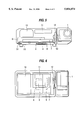
- FIG. 5 is a structural diagram corresponding to FIG. 1 with the exception that the lens unit mounting direction has been modified;
- FIG. 6 is a top view of the structure shown in FIG. 5;
- FIG. 7 is a temperature verses distance chart comparing temperatures of a disadvantageous spaced embodiment using only air for heat conduction and the present invention using a medium for heat conduction.
- FIG. 1 is a structural diagram of a combined portable camera-video (i.e., still camera and video camera) system, showing a central section of the system.
- portable camera-video i.e., still camera and video camera
- the numeral 1 denotes a lens unit (e.g., an automatic or manual focusing 3 ⁇ lens unit), numeral 4 denotes a circuit board with a signal processing circuit mounted thereon, numeral 6 denotes an LSI package for compressing a video signal, numeral 7 denotes a PCMCIA card connector mounted to the circuit board, numeral 9 denotes a card type hard disk drive of a PCMCIA Type 3, numeral 10 denotes a battery, and numeral 11 denotes a liquid crystal display panel, numeral 51 denotes a rubber vibration isolator, and numeral 52 denotes a card slot for the card type hard disk drive.
- a lens unit e.g., an automatic or manual focusing 3 ⁇ lens unit
- numeral 4 denotes a circuit board with a signal processing circuit mounted thereon
- numeral 6 denotes an LSI package for compressing a video signal
- numeral 7 denotes a PCMCIA card connector mounted to the circuit board
- numeral 9 de
- the PCMCIA as referred to herein stands for Personal Computer Memory Card International Association, which is a unified standard name of card type information recording systems used in the field of personal computers.
- PCMCIA standard an external size of PCMCIA devices is standardized at 54.4 mm long by 85.6 mm wide, and the thickness is 3.3 mm in a Type 1 device (which is the thinnest), 5.0 mm in Type 2, and 10.5 mm in Type 3.
- a semiconductor memory e.g., packages or flash memory
- a number and size of parts capable of being incorporated in a card become greater.
- a Type 3 card it is possible to incorporate both a hard disk of 1.8 inch size and a drive unit therefor.
- This hard disk capacity permits a large amount of non-volatile storage, e.g., 200 to 340 M bytes.
- video-audio data of the MPEG1 (Moving Picture Experts Group, ISO 11172 Video-Audio Compressing Standard) format such storage can record a video data volume corresponding to 30 minutes or so. Accordingly, in addition to use of PCMCIA hard disk devices in computers, such recording arrangement is also applicable as a recording medium in a home video camera.
- the external shape of the PCMCIA card is much smaller than that of a typical VTR using an 8 mm tape and requiring an associated tape drive mechanism, it is possible to reduce the size of the system body.
- the present invention is applied to a system using such PCMCIA card type hard disk as a recording medium in a combined video/still camera system, it is possible to attain a reduction of size and cost and improvement of reliability of the system to a greatest extent.
- FIG. 1 is a sectional view of a combined video/still camera system having a reduced size of an external shape, which is 140 mm high, 76 mm wide, and 43 mm thick, exclusive of the lens portion.
- the system operates in the following manner. First, light is condensed by the lens unit 1, such light is focused onto a CCD sensor 2 and is converted thereby into an analog electric signal.
- the lens unit 1 and the CCD portion are connected to the body through a rotating mechanism 12 so as to be rotatable for a predetermined range, e.g., 180°, at the center of the rotating mechanism 12.
- the lens unit 1 When the rotating mechanism 12 is in the state shown in FIG. 1, the lens unit 1 is directed at the same angle as the liquid crystal panel 11, so that it is possible to take a picture of the photographer. On the other hand, when the rotating mechanism 12 is rotated 180°, the lens unit is directed toward an object, thus permitting an ordinary way of use, i.e., with the lens unit directed toward an object and a user viewing the liquid crystal panel.
- the analog output signal from the CCD sensor 2 is transmitted to the circuit board 4 within the camera body through a flexible connector 13 which is inserted through a hole formed centrally within the rotating mechanism 12.
- the signal which has been inputted to the circuit board 4 is first converted to digital data by means of a 10-bit ADC (Analog-to-Digital Converter).
- ADC Analog-to-Digital Converter
- Such data train in this embodiment, is transmitted at 10 bits ⁇ 14.3 MHz.
- the speed is very high and a data volume is very large. It is impossible to store unprocessed data as they are in the recording medium (e.g., due to a large volume thereof).
- the image data is compressed to about one fiftieth by means of the LSI package 6 providing an image compressing encoder which is in conformity with MPEG1.
- an MPEG1-defined header and voice data can be added to the image compressed data, which is then sent to a PCMCIA interface LSI, and is finally recorded in a PCMCIA card type hard disk.
- the signal from the camera obtained simultaneously with the recording signal is monitored by the liquid crystal panel 11, which panel preferably operates as a view finder of the camera.
- the image compressing encoder LSI package 6 is required to operate at a very high speed. As defined by the MPEG1 format, and in order to perform desired processings in real time, i.e., of detecting a motion vector in the signal before compression, suppression of high-frequency component data by DCT (discrete cosine transformation), Huffman coding, and transmission rate control, it is necessary to provide an operation clock as large as 50 to 100 MHz. With regard to such high operation clock frequency, in the case of an LSI package fabricated using a CMOS process, the power consumption increases in proportion to the working frequency. For this reason, the above encoder LSI package 6 consumes power as high as 400 to 500 mW although the supply voltage is set as low as 3 V.
- FIG. 7 representing an illustration of temperature verses distance as encountered within a relevant portion of the camera system. More specifically, curve A represents a plot of internal system temperatures encountered at a printed circuit board surface P, an LSI substrate S, an interior surface I of the housing and an exterior surface E of the housing.
- the encoder LSI package 6 is mounted on the side of the circuit board 4 opposite to the hard disk mounted side, and a thermal conduction plate or medium 5 having a thermal conductivity higher than that of air (such as a thermally conductive rubber plate, copper plate or jell pack) is attached onto the encoder LSI package 6 to conduct heat to the system housing 8 formed of aluminum which itself is high in thermal conductivity.
- the system housing 8 is not limited to being composed of aluminum, but may be constructed of any other thermally conductive material such as copper, magnesium, silver, gold, etc.
- system housing 8 need not be constructed entirely of the heat conductive material, but instead may be only partially constructed of heat conductive material, i.e., as long as sufficient heat conductive material is used to allow such portion of the housing to act as a heat sink to conduct away and dissipate sufficient heat from the LSI package.
- the curve M in FIG. 7 such arrangement including the plate or medium allows internal operating temperatures at the printed circuit board P, the LSI substrate S and an interior surface I of the housing to be lower than the operation guarantee temperature G of the system.
- the arrangement of having the LSI package 6 mounted on a printed circuit board 4 side opposite to a side on which the PCMCIA hard disk drive 9 is mounted is advantageous, in that the printed circuit board 4 can act as a thermal barrier to reduce or block a heat conduction path from the LSI package 6 to the PCMCIA hard disk drive 9.
- Discrete electronic components mounted on the printed circuit board 4 in a space between the printed circuit board 4 and the PCMCIA connector 7 can likewise take advantage of the thermal barrier effect of the printed circuit board, i.e., to be protected from the heat of the LSI package 6.
- Thermal barrier protection can be afforded to the PCMCIA hard disk drive 9 in two additional ways. More particularly, first the PCMCIA connector 7 can be mounted onto the printed circuit board 4 using thermally isolating plastic, non-conductive rubber, or other type of mounts providing a poor thermal conduction path between the printed circuit board 4 and PCMCIA connector 7. Second, the printed circuit board 4 can be sealingly mounted with respect to the housing so as to create two segregated air chambers within the housing 8, i.e., a first chamber defined between the printed circuit board 4 and housing 8 and containing the LSI package 6 therein, and a second chamber defined between the printed circuit board 4 and housing 8 and containing the PCMCIA hard disk drive 9 therein. Segregation of air within the separate chambers reduces heat conduction from the LSI package 6 to the PCMCIA hard disk drive 9 via air conduction.
- the mounting frame 3 can include, for example, rubber, spring and/or foam arrangements provided between the housing 8 and circuit board 4 to isolate, absorb or dissipate transmission of a vibration or impact from the housing 8 to the circuit board, and likewise, rubber, spring and/or foam arrangements an be provided between the circuit board 4 and the PCMCIA card connector 7.
- Such central location and impact/vibration isolation contribute to an operational stability of the hard disk.
- the central location of the PCMCIA hard disk drive 9 is further advantageous in that there is a reduction in hard drive noise which is transmitted to an outside of the housing 8 and heard by a user.
- a plate 5 formed of a thermally conductive rubber or copper having a higher thermal conductivity than air is mounted on the LSI 6, there may be adopted a method which permits omission of such plate. More specifically, by drawing the LSI surface and the system housing very close to each other, for example not larger than 2 mm in terms of spacing between the two, the air which has been heated by the LSI surface is mostly transmitted along the inner surface of the system housing, whereby the heat of the LSI can be transferred efficiently to the system housing.
- the closer the circuit board and especially the LSI package to the system housing the higher the conduction and dissipation of heat using the system housing 8 and the smaller the rise in internal temperature of the system.
- a predetermined close distance e.g. 2 mm
- a predetermined amount of heat transfer to the housing can be guaranteed. Consequently, a combined portable video/still camera system or the like can be realized having a high efficiency without contradiction to reduction in size of the system.
- FIG. 2 is a sectional rear view of the combined portable camera-video system of FIG. 1, and FIG. 3 illustrates sectional view of the PCMCIA card type hard disk drive shown in FIG. 1, such hard disk drive being mounted within a connector conforming to the PCMCIA standard.
- the numeral 14 denotes a hard disk of 1.8 inch size
- numeral 15 denotes a magnetic head thereof.
- the numeral 19 denotes a circuit board on which there are mounted a circuit for controlling said hard disk, a recording/reproducing circuit, etc.
- These components are covered with a housing 16 formed for covering the hard disk portion and a housing 17 formed for a covering circuit board portion, as illustrated in FIG. 3.
- a terminal portion 18 of the PCMCIA connector is formed as thin as about 5 mm in comparison with the hard disk portion which is 10.5 mm thick.
- the thin terminal portion 18 of the PCMCIA and type hard disk drive can be positioned on the inner surface side of the system, and space neighboring the thin terminal portion 18 can be utilized effectively, for example, as the space for the lens rotating mechanism 12.
- FIG. 4 illustrates on a larger scale in a partial cutaway form, the heat radiating means for the encoder LSI package 6 which has been explained above in connection with FIG. 1.
- the same portions as in FIG. 1 are indicated by the same reference numerals.
- heat of several hundred mW generated in the MPEG1 encoder LSI package 6 mounted on the circuit board 4 (also carrying a signal processing circuit thereon) is transmitted to the system housing 8 formed of aluminum or the like.
- Such heat transmission is effected through use of a material or medium 5 of a high thermal conductivity such as, for example, a rubbery material of a high thermal conductivity, a metallic material of a high thermal conductivity such as copper or aluminum, a thermally conductive paste or jell (e.g., jell pack), etc.
- a thermally conductive paste or jell e.g., silicon paste
- a thermally conductive paste or jell can be used within an interface space between the LSI package 6 and the plate 5 and/or interface between the plate 5 and housing 8, to further improve a thermal conduction therebetween and thus an amount of heat transfer to the housing.
- the structure shown in FIG. 4 is characteristic in that the reduction of size and a great reduction of cost can be realized in comparison with a heat radiating plate (e.g., fined heat sink) used with conventional electronic devices. It is optional whether the heat conduction material 5 is to be provided (e.g., mounted) on the LSI side of the circuit board, or on the system housing side. In a preferred embodiment the heat conductive material 5 is a conductive rubber material glued to an inside of the housing 8, and has sufficient resiliency to apply pressure to a contacting LSI package 6 in order to guarantee and improve thermal conduction therebetween.
- a heat radiating plate e.g., fined heat sink
- FIGS. 5 and 6 shows a modification of the system design according to the present invention, of which FIG. 6 is a view obtained by seeing FIG. 5 at a different angle.
- FIG. 6 is a view obtained by seeing FIG. 5 at a different angle.
- the illustrated arrangement is basically the same as in FIG. 1, but the entire system is arranged to be held horizontally while it is in use, i.e., the lens 1 having been provided on a different side of the system in comparison to the FIG. 1 embodiment.
- the liquid crystal panel 11 is disposed rotatedly at right angles as compared with that shown in FIG. 1, and the lens unit 1 is rotated toward an object at the time of photographing.
- the FIG. 5 system may further include legs 50 which allow such system 50 to be set on a horizontal surface (e.g., table).
- Such legs 50 have the advantages of providing non-sliding stability to the system and also allows air conduction to occur under the system, so as to allow air conduction dissipation of heat from the housing 8 to an external environment.
- the liquid crystal panel may be removed, and instead, an optical finder may be attached to the panel-removed portion.
- a further reduction of size may be attained by adopting a fixed structure in place of the rotating mechanism 12.
- a plate or medium formed, e.g., of a thermally conductive rubber or copper higher in thermal conductivity than air, is mounted on the encoder LSI package attached to a side of the circuit board opposite to the hard disk mounted side, to conduct heat to the system housing formed of aluminum or other material high in thermal conductivity, whereby the following effects can be attained.
- the problem that the internal temperature of the system rises to exceed the operating temperature of the LSI package, and the problem that the components, e.g., hard disk, disposed within the system are affected by undissipated heat and raised temperature, are avoided. Accordingly, a marked increases in system reliability is obtained.
- any necessary increase in size of the system due to a conventional heat radiating plate (e.g., finned heat sink) usually employed for the conventional ICs or LSIs is avoided.
- the hard disk can be disposed centrally in the interior of the system, even when an impact or vibration is exerted on the exterior of the system, such impact or vibration is transmitted through the mounting frame, so that the impact or vibration is relatively diminished, thus contributing also to the stability of the hard disk.
- the rotating mechanism etc. can be mounted efficiently because the space formed by the connector and hard disk body of the PCMCIA Type 3 can be utilized effectively.
- the heat of the LSI package can be transferred to the system housing at a high efficiency. Consequently, the closer the circuit board and especially the LSI package to the system housing, the lower can be kept the rise in internal temperature of the system.
- a combined portable camera-video system can be realized very efficiently without contradiction to the reduction in size of the system.
Landscapes
- Engineering & Computer Science (AREA)
- Multimedia (AREA)
- Signal Processing (AREA)
- Physics & Mathematics (AREA)
- Electromagnetism (AREA)
- Studio Devices (AREA)
- Camera Bodies And Camera Details Or Accessories (AREA)
- Mounting Of Printed Circuit Boards And The Like (AREA)
- Casings For Electric Apparatus (AREA)
Applications Claiming Priority (2)
| Application Number | Priority Date | Filing Date | Title |
|---|---|---|---|
| JP7247916A JPH0993475A (ja) | 1995-09-26 | 1995-09-26 | 映像記録再生装置 |
| JP7-247916 | 1995-09-26 |
Publications (1)
| Publication Number | Publication Date |
|---|---|
| US5854874A true US5854874A (en) | 1998-12-29 |
Family
ID=17170468
Family Applications (1)
| Application Number | Title | Priority Date | Filing Date |
|---|---|---|---|
| US08/717,235 Expired - Fee Related US5854874A (en) | 1995-09-26 | 1996-09-20 | Image recording/reproducing system |
Country Status (5)
| Country | Link |
|---|---|
| US (1) | US5854874A (ja) |
| EP (1) | EP0766459B1 (ja) |
| JP (1) | JPH0993475A (ja) |
| KR (1) | KR100233896B1 (ja) |
| DE (1) | DE69618519T2 (ja) |
Cited By (7)
| Publication number | Priority date | Publication date | Assignee | Title |
|---|---|---|---|---|
| US6011690A (en) * | 1997-06-23 | 2000-01-04 | Xircom, Inc. | PC card with thermal management |
| US20020033897A1 (en) * | 2000-09-15 | 2002-03-21 | Douglas Mayne | Drive mounting system for an electronic device |
| US20040223079A1 (en) * | 2003-02-12 | 2004-11-11 | Yoshinobu Shibayama | Image recording apparatus |
| US20090185793A1 (en) * | 2008-01-18 | 2009-07-23 | Akihiro Goto | Information Record and Reproduction Device |
| US10532659B2 (en) * | 2014-12-30 | 2020-01-14 | Joyson Safety Systems Acquisition Llc | Occupant monitoring systems and methods |
| US10614328B2 (en) | 2014-12-30 | 2020-04-07 | Joyson Safety Acquisition LLC | Occupant monitoring systems and methods |
| US10787189B2 (en) | 2014-12-30 | 2020-09-29 | Joyson Safety Systems Acquisition Llc | Occupant monitoring systems and methods |
Families Citing this family (8)
| Publication number | Priority date | Publication date | Assignee | Title |
|---|---|---|---|---|
| ES2174544T3 (es) * | 1998-01-28 | 2002-11-01 | Fujitsu Siemens Computers Gmbh | Dispositivo para el alojamiento de una unidad de disco duro. |
| JPH11331764A (ja) * | 1998-03-20 | 1999-11-30 | Sony Corp | 記録再生装置及び方法 |
| RU2171014C2 (ru) * | 1999-06-28 | 2001-07-20 | Государственное унитарное предприятие "Научно-исследовательский институт промышленного телевидения "Растр" | Телевизионная камера с селективным масштабированием |
| FR2834817B1 (fr) * | 2002-01-17 | 2004-04-09 | Aaton Sa | Appareil portable d'enregistrement |
| EP1655956A3 (en) * | 2004-11-08 | 2006-08-16 | Sony Corporation | Camera apparatus |
| JP2006286036A (ja) * | 2005-03-31 | 2006-10-19 | Orion Denki Kk | 記録再生装置 |
| KR100731372B1 (ko) * | 2005-10-10 | 2007-06-21 | 엘지전자 주식회사 | 영상표시 장치 및 그 제어방법 |
| CN110006944B (zh) * | 2019-04-28 | 2023-12-26 | 扬州大学 | 橡胶支座内部结构导热性能实验研究方法及装置 |
Citations (2)
| Publication number | Priority date | Publication date | Assignee | Title |
|---|---|---|---|---|
| US4547809A (en) * | 1984-04-27 | 1985-10-15 | Rca Corporation | Thermally isolated imager |
| US5027214A (en) * | 1989-04-20 | 1991-06-25 | Olympus Optical Co., Ltd. | Electronic still camera using variable-length data compression for storing still image signals |
Family Cites Families (4)
| Publication number | Priority date | Publication date | Assignee | Title |
|---|---|---|---|---|
| JPH0652933B2 (ja) * | 1988-03-01 | 1994-07-06 | オリンパス光学工業株式会社 | 撮像装置 |
| US5376965A (en) * | 1989-09-14 | 1994-12-27 | Olympus Optical Co., Ltd. | Electronic imaging system capable of recording/reproducing images with any one of several possible recording media |
| US5381176A (en) * | 1991-08-11 | 1995-01-10 | Sony Corporation | Miniaturized video camera |
| US5377060A (en) * | 1992-09-02 | 1994-12-27 | Antek Peripherals, Inc. | Ultra slim data storage module utilizing plural flexible disks |
-
1995
- 1995-09-26 JP JP7247916A patent/JPH0993475A/ja active Pending
-
1996
- 1996-09-17 KR KR1019960040315A patent/KR100233896B1/ko not_active Expired - Fee Related
- 1996-09-19 DE DE69618519T patent/DE69618519T2/de not_active Expired - Fee Related
- 1996-09-19 EP EP96115037A patent/EP0766459B1/en not_active Expired - Lifetime
- 1996-09-20 US US08/717,235 patent/US5854874A/en not_active Expired - Fee Related
Patent Citations (2)
| Publication number | Priority date | Publication date | Assignee | Title |
|---|---|---|---|---|
| US4547809A (en) * | 1984-04-27 | 1985-10-15 | Rca Corporation | Thermally isolated imager |
| US5027214A (en) * | 1989-04-20 | 1991-06-25 | Olympus Optical Co., Ltd. | Electronic still camera using variable-length data compression for storing still image signals |
Cited By (9)
| Publication number | Priority date | Publication date | Assignee | Title |
|---|---|---|---|---|
| US6011690A (en) * | 1997-06-23 | 2000-01-04 | Xircom, Inc. | PC card with thermal management |
| US20020033897A1 (en) * | 2000-09-15 | 2002-03-21 | Douglas Mayne | Drive mounting system for an electronic device |
| US20040223079A1 (en) * | 2003-02-12 | 2004-11-11 | Yoshinobu Shibayama | Image recording apparatus |
| US20090185793A1 (en) * | 2008-01-18 | 2009-07-23 | Akihiro Goto | Information Record and Reproduction Device |
| US10532659B2 (en) * | 2014-12-30 | 2020-01-14 | Joyson Safety Systems Acquisition Llc | Occupant monitoring systems and methods |
| US10614328B2 (en) | 2014-12-30 | 2020-04-07 | Joyson Safety Acquisition LLC | Occupant monitoring systems and methods |
| US10787189B2 (en) | 2014-12-30 | 2020-09-29 | Joyson Safety Systems Acquisition Llc | Occupant monitoring systems and methods |
| US10990838B2 (en) | 2014-12-30 | 2021-04-27 | Joyson Safety Systems Acquisition Llc | Occupant monitoring systems and methods |
| US11667318B2 (en) | 2014-12-30 | 2023-06-06 | Joyson Safety Acquisition LLC | Occupant monitoring systems and methods |
Also Published As
| Publication number | Publication date |
|---|---|
| EP0766459A3 (en) | 2000-02-09 |
| DE69618519T2 (de) | 2002-10-31 |
| EP0766459B1 (en) | 2002-01-16 |
| KR100233896B1 (ko) | 1999-12-15 |
| EP0766459A2 (en) | 1997-04-02 |
| JPH0993475A (ja) | 1997-04-04 |
| KR970019382A (ko) | 1997-04-30 |
| DE69618519D1 (de) | 2002-02-21 |
Similar Documents
| Publication | Publication Date | Title |
|---|---|---|
| US5854874A (en) | Image recording/reproducing system | |
| JP4083521B2 (ja) | 撮像装置 | |
| CN101539711B (zh) | 数码相机 | |
| US6831833B2 (en) | Heat dissipator for optical writing and/or reproducing apparatus | |
| KR100555546B1 (ko) | 집적회로소자 냉각장치 및 이를 구비하는 디스크 드라이브 | |
| CN212413687U (zh) | 散热结构和电子终端 | |
| CN100527929C (zh) | 携带型电子装置 | |
| US7397830B2 (en) | Semiconductor laser device | |
| JP2513567Y2 (ja) | ディスク装置 | |
| JPH0680911B2 (ja) | 電子部品を搭載したプリント配線板の放熱構造 | |
| JP2001057490A (ja) | 回路部品の冷却装置および電子機器 | |
| JP2007166006A (ja) | 撮像装置 | |
| JP2008131251A (ja) | デジタルカメラ | |
| JPH0427256Y2 (ja) | ||
| JP4480689B2 (ja) | 放熱構造及び情報処理装置 | |
| JPH1187959A (ja) | 放熱装置 | |
| JP2003348394A (ja) | Ccdビデオカメラ | |
| JP2002083914A (ja) | 電子回路冷却装置 | |
| JPH0715636A (ja) | カメラ一体型ビデオテープレコーダ | |
| JPH11112923A (ja) | 光ディスクカメラ装置 | |
| JPS6046055A (ja) | 電子部品の冷却装置 | |
| JP2006332841A (ja) | 撮像素子組立体 | |
| JP2002112082A (ja) | 電子カメラ | |
| JPH09130071A (ja) | 携帯型電子装置 | |
| JPS6329999A (ja) | 電子装置モジユ−ル冷却構造 |
Legal Events
| Date | Code | Title | Description |
|---|---|---|---|
| AS | Assignment |
Owner name: HITACHI, LTD., JAPAN Free format text: ASSIGNMENT OF ASSIGNORS INTEREST;ASSIGNORS:YATSUGI, TOMISHIGE;KIMURA, MASAYUKI;REEL/FRAME:008253/0185 Effective date: 19960904 |
|
| FEPP | Fee payment procedure |
Free format text: PAYOR NUMBER ASSIGNED (ORIGINAL EVENT CODE: ASPN); ENTITY STATUS OF PATENT OWNER: LARGE ENTITY |
|
| FPAY | Fee payment |
Year of fee payment: 4 |
|
| FPAY | Fee payment |
Year of fee payment: 8 |
|
| REMI | Maintenance fee reminder mailed | ||
| LAPS | Lapse for failure to pay maintenance fees | ||
| STCH | Information on status: patent discontinuation |
Free format text: PATENT EXPIRED DUE TO NONPAYMENT OF MAINTENANCE FEES UNDER 37 CFR 1.362 |