US5880666A - Fuse with press-connecting terminals and wire cutter - Google Patents
Fuse with press-connecting terminals and wire cutter Download PDFInfo
- Publication number
- US5880666A US5880666A US08/940,962 US94096297A US5880666A US 5880666 A US5880666 A US 5880666A US 94096297 A US94096297 A US 94096297A US 5880666 A US5880666 A US 5880666A
- Authority
- US
- United States
- Prior art keywords
- press
- fuse
- connecting terminals
- pair
- sheathed wire
- Prior art date
- Legal status (The legal status is an assumption and is not a legal conclusion. Google has not performed a legal analysis and makes no representation as to the accuracy of the status listed.)
- Expired - Lifetime
Links
Images



Classifications
-
- H—ELECTRICITY
- H01—ELECTRIC ELEMENTS
- H01H—ELECTRIC SWITCHES; RELAYS; SELECTORS; EMERGENCY PROTECTIVE DEVICES
- H01H85/00—Protective devices in which the current flows through a part of fusible material and this current is interrupted by displacement of the fusible material when this current becomes excessive
- H01H85/02—Details
- H01H85/20—Bases for supporting the fuse; Separate parts thereof
- H01H85/201—Bases for supporting the fuse; Separate parts thereof for connecting a fuse in a lead and adapted to be supported by the lead alone
-
- H—ELECTRICITY
- H01—ELECTRIC ELEMENTS
- H01H—ELECTRIC SWITCHES; RELAYS; SELECTORS; EMERGENCY PROTECTIVE DEVICES
- H01H1/00—Contacts
- H01H1/58—Electric connections to or between contacts; Terminals
- H01H1/5844—Electric connections to or between contacts; Terminals making use of wire-gripping clips or springs
- H01H1/585—Electric connections to or between contacts; Terminals making use of wire-gripping clips or springs and piercing the wire insulation
Definitions
- This invention relates to a fuse incorporated in an electric circuit in an automobile or the like so as to prevent an excess current from continuing to flow in the event of an abnormal condition such as a short-circuit, and the invention also relates to a method of mounting such a fuse.
- a fuse incorporated in an electric circuit, has a capacity corresponding to an allowable current of a load, and when the user adds a new load, or exchanges the load with a different load, it is necessary to add a new fuse so as to protect the circuit.
- electric loads such as a radio, a television set, a car navigation device and a clock
- a junction box containing fuses For example, in an electric system of an automobile, electric loads, such as a radio, a television set, a car navigation device and a clock, are connected in a parallel manner to a power source via a junction box containing fuses.
- the maker uses appropriate fuses corresponding to these loads associated with the electric system of the automobile.
- a housing made of an insulative resin including a lid and a housing body
- the fuse body received in the housing, the fuse body having a pair of press-connecting terminals which are arranged in a staggered manner and to which a sheathed wire is press-connected to and retained, and a melting portion formed between the pair of press-connecting terminals;
- sheathed wire comprises a pair of cut end portions formed by cutting a portion of the sheathed wire located between the pair of press-connecting terminals after the sheathed wire is mounted on the pair of press-connecting terminals.
- a projection is formed on an inner surface of the lid so as to hold cut end portions of the sheathed wire apart from each other when the lid is closed.
- the melting portion of the fuse body may be embedded in the housing body of the housing.
- a housing made of an insulative resin including a lid and a housing body
- the fuse body received in the housing, the fuse body having a pair of press-connecting terminals to which a sheathed wire is press-connected and having a melting portion formed between the pair of press-connecting terminals;
- sheathed wire comprises a pair of cut end portions formed by cutting a portion of the sheathed wire located between the pair of press-connecting terminals after the sheathed wire is mounted on the pair of press-connecting terminals, and
- a projection is formed on an inner surface of the lid so as to hold the cut end portions of the sheathed wire apart from each other when the lid is closed.
- the melting portion of the fuse body is embedded in the housing body of the housing by providing an integral molding construction.
- the above object of the invention has been achieved by a mounting method for mounting on a fuse in a desired circuit in which the fuse comprises: a housing made of an insulative resin including a lid and a housing body; a fuse body received in the housing, the fuse body having a pair of press-connecting terminals arranged in a staggered manner and having a melting portion formed between the pair of press-connecting terminals; the mounting method comprising the steps of:
- a projection may be formed on an inner surface of the lid, and the mounting method may further comprises the steps of:
- the above object of the invention has been achieved by a mounting method for mounting on a fuse in a desired circuit in which the fuse comprises: a housing made of an insulative resin including a housing body and a lid with a projection on its inner surface; a fuse body received in the housing, the fuse body having a pair of press-connecting terminals and a melting portion formed between the pair of press-connecting terminals; the mounting method comprising the steps of:
- a predetermined length of this mounted portion may be cut off.
- FIG. 1 is a perspective view showing a fuse body of a first embodiment of the invention
- FIG. 2 is a perspective view showing the overall construction of the fuse in which the fuse body is received in a housing;
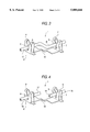
- FIG. 3 is a perspective view showing a condition in which a sheathed wire is mounted on press-connecting terminals of the fuse body;
- FIG. 4 is a perspective view showing a condition in which the mounted portion of the sheathed wire is cut
- FIG. 5 is a vertical cross-sectional view in which the fused is mounted
- FIG. 6 is a perspective view of a modified form of the invention, showing a condition in which a sheathed wire is mounted on press-connecting terminals of a fuse body;
- FIG. 7 is a perspective view showing a fuse body of a second embodiment of the invention.
- FIG. 1 is a perspective view showing a fuse body 1 of the first embodiment of the invention
- FIG. 2 is a perspective view showing the overall construction of the fuse 15 in which the fuse body 1 is received in a housing 2.
- the fuse 15 comprises the fuse body 1 formed by pressing a metal sheet, and the housing 2 made of an insulative resin receiving the fuse body 1.
- the fuse body 1 comprises a pair of press-connecting terminals 4 and 5 arranged in a staggered manner, and a narrow melting portion 10 formed between these press-connecting terminals 4 and 5 so called as a crimping terminal in general.
- the press-connecting terminals 4 and 5 have vertically upstanding press-connecting grooves 6 and 7, respectively, and vertical inner edges of the press-connecting grooves 6 and 7 constitutes press-connecting blades 8 and 9.
- the housing 2 of a generally box-shape comprises a housing body 11 and a lid 3.
- the lid 3 is connected to the housing body 11 by a hinge 3a.
- Wire pressing portions 23 are formed in a projected manner on opposite ends of the lid 3, respectively, and when the lid 3 is closed, these wire pressing portions 23 press a sheathed wire 16 as shown in FIG. 5.
- a lock arm 20 is formed on a swingable side edge portion of the lid 3.
- a retaining projection 21 is formed at a distal end of this lock arm 20, to thereby be locked to a retaining portion 22 on the housing body 11.
- the housing 2 is molded of a heat-resistant resin.
- a projection 13 is formed on an inner surface 12 of the lid 3, and this projection 13 is inserted into a space between the press-connecting terminals 4 and 5 of the fuse body 1 when the lid 3 is closed.
- the fuse body 1 is integrally molded in the housing body 11 along a bottom plate 14 thereof, or is fitted into the housing body 11 after the housing body 11 is molded. In the case where the melting portion 10 of the fuse body 1 is embedded in the housing body 11 by integrally molding them, the melting portion 10 is less liable to be influenced by the outside temperature, and the generation of an arc during the melting of the melting portion 10 is suppressed.
- FIGS. 3 to 5 A method of mounting the above fuse 15 of this embodiment at an intermediate portion of a circuit will now be described with reference to FIGS. 3 to 5.
- FIGS. 3 and 4 an illustration of the housing 2 is omitted.
- a portion of the sheathed wire 16, to which the fuse is to be attached is mounted between the press-connecting terminals 4 and 5 of the fuse body 1.
- the sheathed wire 16 is press-fitted into the press-connecting grooves 6 and 7 of the press-connecting terminals 4 and 5, so that the cutting blades 8 and 9 cut a sheath of the wire, thereby electrically connecting the press-connecting terminals 4 and 5 to a conductor in the wire.
- the mounted portion of the sheathed wire 16 between the two press-connecting terminals 4 and 5 is bent into a generally crank-like configuration above the melting portion 10 since the upstanding press-connecting terminals 4 and 5 are arranged in a staggered manner as described above.
- the mounted portion of the sheathed wire 16 between the two press-connecting terminals is cut at its central portion, or a predetermined length of this mounted portion (indicated by dot-and-dash lines A and B in FIG. 3) is cut off, and therefore the sheathed wire 16 is severed into two parts, and at the same time these two parts are electrically connected together through the fuse body 1.
- Cut end portions 17 and 18 of the sheathed wire 16, cut at the central portion of the above mounted portion, are brought into a straight condition because of their elastic restoring force since the opposite ends of the mounted portion of the sheathed wire 16 are respectively press-connected to and retained by the press-connecting terminals 4 and 5 arranged in a staggered manner, and as a result the cut end portions 17 and 18 are kept spaced from each other.
- the lid 3 of the housing 2 is closed relative to the housing body 11.
- the projection 13, formed on the inner surface 12 of the lid 13 bends the two cut end portions 17 and 18 of the sheathed wire 16 downward, and holds them apart from each other, as shown in FIG. 5.
- the lid 3 is retained on the retaining portion 22 of the housing body 11 by the retaining projection 21 of the lock arm 20, thus completing the mounting of the fuse 15.
- the sheathed wire 16 is mounted on the press-connecting terminals 4 and 5, and is press-connected to and retained by these terminals 4 and 5, and then a portion of the sheathed wire 16, mounted between the two press-connecting terminals 4 and 5, is cut, and then the lid 3 is closed.
- the fuse can be easily mounted at an intermediate portion of the existing circuit.
- the projection 13 bends the two cut end portions 17 and 18 downward, and holds them apart from each other.
- the press-connecting terminals 4 and 5 are arranged in a staggered manner as in the fuse body of this embodiment, it is not always necessary to provide the projection 13 since the cut end portions 17 and 18 of the sheathed wire 16 are brought into a straight condition, and are kept spaced from each other because of their elastic restoring force.
- FIG. 6 there can be used an arrangement in which when the sheathed wire 16 is press-fitted into the press-connecting grooves 6 and 7 of the press-connecting terminals 4 and 5 to thereby cut the sheath by the cutting blades 8 and 9, thereby electrically connecting the press-connecting terminals 4 and 5 to the conductor in the sheathed wire, a portion of the sheathed wire 16, mounted between the press-connecting terminals 4 and 5, extends straight above the melting portion 10.
- the cut end portions of the sheathed wire 16, cut at the central portion of the above mounted portion are brought into a straight condition because of their elastic restoring force since the opposite ends of the mounted portion of the sheathed wire 16 are respectively press-connected to and retained by the press-connecting terminals 4 and 5 arranged in a staggered manner, and as a result the cut end portions 17 and 18 are kept spaced from each other.
- FIG. 7 is a perspective view of fuse body 31 of a second embodiment of the invention.
- the fuse body 31 comprises a pair of press-connecting terminals 24 and 25 arranged on a common straight line, and a narrow melting portion 30 formed between these press-connecting terminals 24 and 25.
- the press-connecting terminals 24 and 25 have vertical press-connecting grooves 26 and 27, respectively, and vertical inner edges of the press-connecting grooves 26 and 27 constitutes press-connecting blades 28 and 29.
- a housing, receiving this fuse body 31, is similar in construction to the housing 2 of the above first embodiment.
- a portion of the sheathed wire 16, to which the fuse is to be attached is mounted between the press-connecting terminals 24 and 25 of the fuse body 31.
- the sheathed wire 16 is press-fitted into the press-connecting grooves 26 and 27 of the press-connecting terminals 24 and 25, so that the cutting blades 28 and 29 cut the sheath of the wire, thereby electrically connecting the press-connecting terminals 24 and 25 to the conductor in the wire.
- the mounted portion of the sheathed wire 16 between the press-connecting terminals 24 and 25 extends straight above the melting portion 30 since the upstanding press-connecting terminals 24 and 25 are arranged on the common straight line as described above.
- the mounted portion of the sheathed wire 16 between the two press-connecting terminals is cut at its central portion, or a predetermined length of this mounted portion is cut off, and therefore the sheathed wire 16 is severed into two parts, and at the same time these two parts are electrically connected together through the fuse body 31.
- a projection 13 formed on an inner surface of this lid bends two cut end portions of the sheathed wire 16 downward, and holds them apart from each other.
- the fuse having the fuse body 31 of this embodiment when the mounted portion of the sheathed wire 16 is merely cut at its central portion, it is essential to form the projection on the inner surface of the lid so as to hold the two cut end portions apart from each other.
- the housing and fuse body of the fuses of the invention are not limited to those in the above embodiments, and various modifications can be made.
- the melting portion of the fuse body can have any suitable shape, such as a U-shape, an S-shape and a constricted shape, depending on the load. By increasing only the thickness of the melting portion, the fuse of a desired rating can be provided.
- a portion of the sheathed wire is mounted between the press-connecting terminals, and the sheathed wire is press-connected to and retained by these terminals, and then the mounted portion of the sheathed wire is cut, and the lid is closed.
- the fuse can be easily mounted at an intermediate portion of the existing circuit.
- the existing circuit can be used by mounting the fuse of the invention at the existing circuit, and there is no need to provide a new circuit. And besides, when the user adds a new electric part, the fuse of the invention can be easily mounted at an intermediate portion of the existing circuit, and therefore the new electric part can be easily protected from an excess current.
- the fuse which can be easily mounted at the existing circuit, as well as the method of mounting the fuse, can be provided.
Landscapes
- Fuses (AREA)
Applications Claiming Priority (2)
| Application Number | Priority Date | Filing Date | Title |
|---|---|---|---|
| JP26313096A JP3322808B2 (ja) | 1996-10-03 | 1996-10-03 | ヒューズ及びその取付方法 |
| JP8-263130 | 1996-10-03 |
Publications (1)
| Publication Number | Publication Date |
|---|---|
| US5880666A true US5880666A (en) | 1999-03-09 |
Family
ID=17385240
Family Applications (1)
| Application Number | Title | Priority Date | Filing Date |
|---|---|---|---|
| US08/940,962 Expired - Lifetime US5880666A (en) | 1996-10-03 | 1997-09-30 | Fuse with press-connecting terminals and wire cutter |
Country Status (2)
| Country | Link |
|---|---|
| US (1) | US5880666A (ja) |
| JP (1) | JP3322808B2 (ja) |
Cited By (6)
| Publication number | Priority date | Publication date | Assignee | Title |
|---|---|---|---|---|
| EP1093195A1 (de) * | 1999-10-15 | 2001-04-18 | Endress + Hauser GmbH + Co. | Elektrische Sicherungsvorrichtung |
| US20050057110A1 (en) * | 2003-09-15 | 2005-03-17 | Wolfe Melvin E. | Electric motor |
| US20060028314A1 (en) * | 2002-12-27 | 2006-02-09 | Sony Chemicals Corp. | Protective element |
| FR2885270A1 (fr) * | 2005-04-29 | 2006-11-03 | Peugeot Citroen Automobiles Sa | Dispositif de protection par fusibles de lignes alimentant des organes electriques differentes, notamment d'un vehicule automobile. |
| US20080022521A1 (en) * | 2004-03-05 | 2008-01-31 | Simofi-Iiyes Attila | Universal terminal bar structure with ground contacting feature integrated into a body structure with versatile RFI suppression for electric motors |
| US20170323747A1 (en) * | 2015-01-27 | 2017-11-09 | Leoni Bordnetz-Systeme Gmbh | Pyrotechnic safety element |
Families Citing this family (2)
| Publication number | Priority date | Publication date | Assignee | Title |
|---|---|---|---|---|
| JP3242863B2 (ja) * | 1997-06-10 | 2001-12-25 | 矢崎総業株式会社 | 温度ヒューズ |
| US10431971B2 (en) * | 2017-01-04 | 2019-10-01 | Te Connectivity Corporation | Thermal protector |
Citations (3)
| Publication number | Priority date | Publication date | Assignee | Title |
|---|---|---|---|---|
| US4237513A (en) * | 1978-10-25 | 1980-12-02 | Stephen Foldes | Thermoconstrictive disconnect of conductors in electrical apparatus |
| US4679877A (en) * | 1985-07-17 | 1987-07-14 | Ahroni Joseph M | Electric plug with snap-fitted housing components |
| JPH01134935A (ja) * | 1987-11-20 | 1989-05-26 | Fujitsu Ltd | 半導体装置の製造方法 |
-
1996
- 1996-10-03 JP JP26313096A patent/JP3322808B2/ja not_active Expired - Fee Related
-
1997
- 1997-09-30 US US08/940,962 patent/US5880666A/en not_active Expired - Lifetime
Patent Citations (3)
| Publication number | Priority date | Publication date | Assignee | Title |
|---|---|---|---|---|
| US4237513A (en) * | 1978-10-25 | 1980-12-02 | Stephen Foldes | Thermoconstrictive disconnect of conductors in electrical apparatus |
| US4679877A (en) * | 1985-07-17 | 1987-07-14 | Ahroni Joseph M | Electric plug with snap-fitted housing components |
| JPH01134935A (ja) * | 1987-11-20 | 1989-05-26 | Fujitsu Ltd | 半導体装置の製造方法 |
Cited By (10)
| Publication number | Priority date | Publication date | Assignee | Title |
|---|---|---|---|---|
| EP1093195A1 (de) * | 1999-10-15 | 2001-04-18 | Endress + Hauser GmbH + Co. | Elektrische Sicherungsvorrichtung |
| US20060028314A1 (en) * | 2002-12-27 | 2006-02-09 | Sony Chemicals Corp. | Protective element |
| US7286037B2 (en) | 2002-12-27 | 2007-10-23 | Sony Corporation | Protective element |
| US20050057110A1 (en) * | 2003-09-15 | 2005-03-17 | Wolfe Melvin E. | Electric motor |
| AU2004203073B2 (en) * | 2003-09-15 | 2009-12-17 | Shop Vac Corporation | Electric motor |
| US8141231B2 (en) * | 2003-09-15 | 2012-03-27 | Shop Vac | Electric motor |
| US20080022521A1 (en) * | 2004-03-05 | 2008-01-31 | Simofi-Iiyes Attila | Universal terminal bar structure with ground contacting feature integrated into a body structure with versatile RFI suppression for electric motors |
| FR2885270A1 (fr) * | 2005-04-29 | 2006-11-03 | Peugeot Citroen Automobiles Sa | Dispositif de protection par fusibles de lignes alimentant des organes electriques differentes, notamment d'un vehicule automobile. |
| US20170323747A1 (en) * | 2015-01-27 | 2017-11-09 | Leoni Bordnetz-Systeme Gmbh | Pyrotechnic safety element |
| US10529516B2 (en) * | 2015-01-27 | 2020-01-07 | Leoni Bordnetz-Systeme Gmbh | Pyrotechnic safety element |
Also Published As
| Publication number | Publication date |
|---|---|
| JPH10112252A (ja) | 1998-04-28 |
| JP3322808B2 (ja) | 2002-09-09 |
Similar Documents
| Publication | Publication Date | Title |
|---|---|---|
| US4391485A (en) | In-line fuse holder for miniature plug-in fuse | |
| US5795193A (en) | Power distribution box with busbar having bolt retaining means | |
| TW531763B (en) | Blade fuse | |
| EP1130616B1 (en) | Fuse and fuse support | |
| US20080061920A1 (en) | Fuse cavity structure and electric connection box | |
| US9685294B2 (en) | Fuse | |
| US6529113B2 (en) | Push-in type fuse | |
| JP2003037920A (ja) | 電気接続箱 | |
| US7479866B2 (en) | Low profile automotive fuse | |
| JPH05205608A (ja) | ヒューズ組立体 | |
| US4199214A (en) | Fused electrical connector | |
| US6794979B2 (en) | Fuse holder assembly | |
| EP3511971B1 (en) | Multi-part symmetrical fuse assembly | |
| EP0720256B1 (en) | Electrical connection box and contact bonding terminal used therefor | |
| US4128291A (en) | Fuse adapter terminal | |
| JP7412035B1 (ja) | ヒューズ、及び当該ヒューズの製造方法 | |
| JP3322808B2 (ja) | ヒューズ及びその取付方法 | |
| US5882229A (en) | Fuse tap | |
| US4613192A (en) | Power cord strain relief | |
| JPH0833162A (ja) | 電気接続箱の接続構造 | |
| US5951333A (en) | Hinged wire route plate | |
| JPH0883654A (ja) | 大電流接続用ターミナルおよび該ターミナルを用いた電気接続箱の接続構造 | |
| CA2260690A1 (en) | Multiple terminal/branch circuit fuse | |
| US20020024414A1 (en) | Fuse and fuse-mounting electric connection box | |
| JP2929415B2 (ja) | ヒューズの二次ショート防止構造 |
Legal Events
| Date | Code | Title | Description |
|---|---|---|---|
| AS | Assignment |
Owner name: YAZAKI CORPORATION, JAPAN Free format text: ASSIGNMENT OF ASSIGNORS INTEREST;ASSIGNORS:MATSUOKA, NAOKI;MURAMATSU, KENJI;REEL/FRAME:009079/0448 Effective date: 19971029 |
|
| STCF | Information on status: patent grant |
Free format text: PATENTED CASE |
|
| FEPP | Fee payment procedure |
Free format text: PAYOR NUMBER ASSIGNED (ORIGINAL EVENT CODE: ASPN); ENTITY STATUS OF PATENT OWNER: LARGE ENTITY |
|
| FPAY | Fee payment |
Year of fee payment: 4 |
|
| FPAY | Fee payment |
Year of fee payment: 8 |
|
| FPAY | Fee payment |
Year of fee payment: 12 |