US5890983A - Cooling apparatus of a gear transmission having an electromagnetic clutch - Google Patents
Cooling apparatus of a gear transmission having an electromagnetic clutch Download PDFInfo
- Publication number
- US5890983A US5890983A US08/789,724 US78972497A US5890983A US 5890983 A US5890983 A US 5890983A US 78972497 A US78972497 A US 78972497A US 5890983 A US5890983 A US 5890983A
- Authority
- US
- United States
- Prior art keywords
- passage
- cooling
- gear
- outer member
- gear case
- Prior art date
- Legal status (The legal status is an assumption and is not a legal conclusion. Google has not performed a legal analysis and makes no representation as to the accuracy of the status listed.)
- Expired - Fee Related
Links
- 238000001816 cooling Methods 0.000 title claims abstract description 96
- 230000005540 biological transmission Effects 0.000 title claims abstract description 17
- 239000002826 coolant Substances 0.000 claims description 22
- 239000010687 lubricating oil Substances 0.000 claims description 11
- 239000000498 cooling water Substances 0.000 description 47
- 239000006249 magnetic particle Substances 0.000 description 18
- 238000010276 construction Methods 0.000 description 11
- XEEYBQQBJWHFJM-UHFFFAOYSA-N Iron Chemical compound [Fe] XEEYBQQBJWHFJM-UHFFFAOYSA-N 0.000 description 7
- 230000000694 effects Effects 0.000 description 7
- 239000000843 powder Substances 0.000 description 7
- 238000000926 separation method Methods 0.000 description 7
- JEIPFZHSYJVQDO-UHFFFAOYSA-N iron(III) oxide Inorganic materials O=[Fe]O[Fe]=O JEIPFZHSYJVQDO-UHFFFAOYSA-N 0.000 description 5
- XAGFODPZIPBFFR-UHFFFAOYSA-N aluminium Chemical compound [Al] XAGFODPZIPBFFR-UHFFFAOYSA-N 0.000 description 4
- 229910052782 aluminium Inorganic materials 0.000 description 4
- 230000002093 peripheral effect Effects 0.000 description 4
- 230000020169 heat generation Effects 0.000 description 3
- 229910052742 iron Inorganic materials 0.000 description 3
- 239000007788 liquid Substances 0.000 description 3
- 238000012423 maintenance Methods 0.000 description 3
- 239000000463 material Substances 0.000 description 3
- 230000007935 neutral effect Effects 0.000 description 3
- 239000000110 cooling liquid Substances 0.000 description 2
- 230000005611 electricity Effects 0.000 description 2
- 238000005192 partition Methods 0.000 description 2
- 230000002265 prevention Effects 0.000 description 2
- XLYOFNOQVPJJNP-UHFFFAOYSA-N water Substances O XLYOFNOQVPJJNP-UHFFFAOYSA-N 0.000 description 2
- 229910000831 Steel Inorganic materials 0.000 description 1
- 230000015572 biosynthetic process Effects 0.000 description 1
- 230000007797 corrosion Effects 0.000 description 1
- 238000005260 corrosion Methods 0.000 description 1
- 238000007599 discharging Methods 0.000 description 1
- 238000004519 manufacturing process Methods 0.000 description 1
- 230000004048 modification Effects 0.000 description 1
- 238000012986 modification Methods 0.000 description 1
- 238000007789 sealing Methods 0.000 description 1
- 239000010959 steel Substances 0.000 description 1
- 230000001131 transforming effect Effects 0.000 description 1
Images



Classifications
-
- F—MECHANICAL ENGINEERING; LIGHTING; HEATING; WEAPONS; BLASTING
- F16—ENGINEERING ELEMENTS AND UNITS; GENERAL MEASURES FOR PRODUCING AND MAINTAINING EFFECTIVE FUNCTIONING OF MACHINES OR INSTALLATIONS; THERMAL INSULATION IN GENERAL
- F16H—GEARING
- F16H57/00—General details of gearing
- F16H57/04—Features relating to lubrication or cooling or heating
- F16H57/0412—Cooling or heating; Control of temperature
- F16H57/0415—Air cooling or ventilation; Heat exchangers; Thermal insulations
-
- F—MECHANICAL ENGINEERING; LIGHTING; HEATING; WEAPONS; BLASTING
- F16—ENGINEERING ELEMENTS AND UNITS; GENERAL MEASURES FOR PRODUCING AND MAINTAINING EFFECTIVE FUNCTIONING OF MACHINES OR INSTALLATIONS; THERMAL INSULATION IN GENERAL
- F16D—COUPLINGS FOR TRANSMITTING ROTATION; CLUTCHES; BRAKES
- F16D37/00—Clutches in which the drive is transmitted through a medium consisting of small particles, e.g. centrifugally speed-responsive
- F16D37/02—Clutches in which the drive is transmitted through a medium consisting of small particles, e.g. centrifugally speed-responsive the particles being magnetisable
-
- F—MECHANICAL ENGINEERING; LIGHTING; HEATING; WEAPONS; BLASTING
- F16—ENGINEERING ELEMENTS AND UNITS; GENERAL MEASURES FOR PRODUCING AND MAINTAINING EFFECTIVE FUNCTIONING OF MACHINES OR INSTALLATIONS; THERMAL INSULATION IN GENERAL
- F16H—GEARING
- F16H3/00—Toothed gearings for conveying rotary motion with variable gear ratio or for reversing rotary motion
- F16H3/44—Toothed gearings for conveying rotary motion with variable gear ratio or for reversing rotary motion using gears having orbital motion
- F16H3/72—Toothed gearings for conveying rotary motion with variable gear ratio or for reversing rotary motion using gears having orbital motion with a secondary drive, e.g. regulating motor, in order to vary speed continuously
- F16H3/721—Toothed gearings for conveying rotary motion with variable gear ratio or for reversing rotary motion using gears having orbital motion with a secondary drive, e.g. regulating motor, in order to vary speed continuously the secondary drive being an energy dissipating device, e.g. regulating brake, in order to vary speed continuously
-
- F—MECHANICAL ENGINEERING; LIGHTING; HEATING; WEAPONS; BLASTING
- F16—ENGINEERING ELEMENTS AND UNITS; GENERAL MEASURES FOR PRODUCING AND MAINTAINING EFFECTIVE FUNCTIONING OF MACHINES OR INSTALLATIONS; THERMAL INSULATION IN GENERAL
- F16H—GEARING
- F16H57/00—General details of gearing
- F16H57/04—Features relating to lubrication or cooling or heating
- F16H57/048—Type of gearings to be lubricated, cooled or heated
- F16H57/0482—Gearings with gears having orbital motion
-
- F—MECHANICAL ENGINEERING; LIGHTING; HEATING; WEAPONS; BLASTING
- F16—ENGINEERING ELEMENTS AND UNITS; GENERAL MEASURES FOR PRODUCING AND MAINTAINING EFFECTIVE FUNCTIONING OF MACHINES OR INSTALLATIONS; THERMAL INSULATION IN GENERAL
- F16D—COUPLINGS FOR TRANSMITTING ROTATION; CLUTCHES; BRAKES
- F16D37/00—Clutches in which the drive is transmitted through a medium consisting of small particles, e.g. centrifugally speed-responsive
- F16D2037/002—Clutches in which the drive is transmitted through a medium consisting of small particles, e.g. centrifugally speed-responsive characterised by a single substantially axial gap in which the fluid or medium consisting of small particles is arranged
-
- Y—GENERAL TAGGING OF NEW TECHNOLOGICAL DEVELOPMENTS; GENERAL TAGGING OF CROSS-SECTIONAL TECHNOLOGIES SPANNING OVER SEVERAL SECTIONS OF THE IPC; TECHNICAL SUBJECTS COVERED BY FORMER USPC CROSS-REFERENCE ART COLLECTIONS [XRACs] AND DIGESTS
- Y10—TECHNICAL SUBJECTS COVERED BY FORMER USPC
- Y10T—TECHNICAL SUBJECTS COVERED BY FORMER US CLASSIFICATION
- Y10T74/00—Machine element or mechanism
- Y10T74/21—Elements
- Y10T74/2186—Gear casings
- Y10T74/2189—Cooling
Definitions
- the present invention relates to a power transmission apparatus used for a clutch or a brake, and particularly to a cooling structure thereof.
- an magnetic particle type electromagnetic clutch having an outer member forming an annular space, an inner member arranged inside of the outer member and electromagnetic powder of magnetic particles interposed between the outer and inner members, when an exciting coil supported by the outer member is charged with electricity to produce a magnetic field, magnetic particles in the electromagnetic powder are magnetized and a linkage of the magnetic particles is formed for connecting the outer and inner members.
- the exciting coil is not charged with electricity, the outer and inner members are disconnected so as to freely rotate mutually.
- the cooling water passage is formed within an inner member or an outer member, so that it is advantageous spatially and the electromagnetic clutch itself does not become large.
- cooling water passage is formed in the inner or outer member, construction of the member becomes complicated and the working is very troublesome. In case of a clutch which is connected and disconnected while both inner and outer members rotate, formation of the cooling water passage at a boundary between a fixed part and a rotating part is difficult. When the cooling water passage is formed in the inner member, cooling effect against heat generation of the exciting coil is small.
- the inner and outer members must be worked with high accuracy or sealed surely so that the cooling water passage is blocked surely from the electromagnetic powder and the exciting coil, which are apt to be influenced by liquid, and no leak of the cooling water occurs. This is difficult technically and results in a high cost, sometimes.
- the cooling water passage When the cooling water passage is formed within the inner or outer member, it is difficult to form fins within a limited interior space resulting in a small heat transmitting area, therefore a large quantity of water must be flowed in order to obtain a high cooling effect. If the cooling water passage is made of iron or steel material apt to rust, there is the possibility that the passage is stopped up by the rust, therefore complications on use such as rust prevention, administration of the cooling liquid, periodical maintenance are accompanied.
- the present invention has been accomplished in view of the foregoing and an object of the invention is to provide a cooling structure of a power transmission apparatus in which the construction is simple and easily worked, it is easy to provide fins for improving cooling effect, there is no complication on use and both a clutch side and a gear device side can be cooled concurrently.
- the present invention provides a cooling structure of a power transmission apparatus having an electromagnetic clutch including a fixed outer member with an exciting coil and a rotary inner member adapted to be fixed to the outer member by controlling electric energy provided to the exciting coil, and a gear device connected to the inner member, comprising a cooling apparatus positioned between the outer member and a gear case member housing the gear device.
- the cooling apparatus is provided utilizing a dead space between the fixed outer member of the electromagnetic clutch and the gear case member, it can be avoided that the power transmission apparatus becomes large owing to the cooling apparatus. Since the cooling apparatus is provided outside of the outer member, the construction can be simplified, the working is easy, the cooling medium can be sealed simply and surely, and the maintenance is also easy without accompanying complications on use.
- Both slipping portion between the outer and inner members and the exciting coil, which are the heat sources, can be cooled by the cooling apparatus with a high cooling efficiency.
- the cooling apparatus concurrently cools the gear device side too, so that another cooling apparatus is unnecessary.
- the above-mentioned gear device may be a planetary gear device having a first gear element connected to an input member for inputting a rotational driving force, a second gear element connected to an output member and a third gear element connected to the inner member of the electromagnetic clutch. According to this configuration, a power transmission apparatus with a variable-speed mechanism can be constituted easily.
- the above-mentioned cooling apparatus may have a passage for cooling medium formed by fins projected from the outer member toward the gear case member. According to this configuration, a large heat transmitting area is ensured within a narrow space to improve the cooling effect and therefore it is unnecessary to let a large quantity of cooling medium flow. Since the fins are formed outside of the outer member, the work is easy.
- the above-mentioned passage for cooling medium may have an outlet port at an uppermost portion of the passage and an inlet port at a portion lower than the outlet port.
- air within the cooling apparatus is discharged from the outlet port at the uppermost position and never stay in the cooling medium passage so that an efficient cooling can be maintained.
- a second passage for cooling medium constituting a heat exchange portion to an interior of the gear case member may be formed between the outer member and the gear case member in addition to the above-mentioned first passage for cooling medium. According to this configuration, both the electromagnetic clutch and the gear device can be cooled efficiently by only one cooling apparatus.
- the first and second passages may be connected with each other positioning the second passage at an upper stream side of flow of the cooling medium and the first passage at a lower stream side of flow of the cooling medium.
- the cooling medium flows firstly through the second passage constituting the heat exchange portion to the interior of the gear case member in which heat generation and temperature are lower than those in the electromagnetic clutch, and then flows through the first passage of higher temperature, so that an efficient cooling can be obtained.
- a lubricating oil introducing port may be provided at the heat exchange portion. Since the lubricating oil is cooled at the heat exchange portion by the cooling medium then supplied to the gear device, the gear device is cooled very effectively.
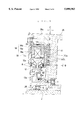
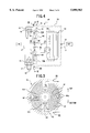
- FIG. 1 is a rough constitutional view of a variable-speed apparatus according to a preferred embodiment of the present invention
- FIG. 2 is a sectional view along the line II--II of FIG. 1 ;
- FIG. 3 is a sectional view showing a concrete construction of an essential part of the variable-speed apparatus
- FIG. 4 is a rough constitutional view of a variable-speed apparatus according to another embodiment of the present invention.
- FIG. 5 is a sectional view along the line V--V of FIG. 4;
- FIG. 6 is a sectional view showing a concrete construction of an essential part of the variable-speed apparatus
- FIG. 7 is a sectional view similar to FIG. 6 showing a modification
- FIG. 8 is a rough constitutional view of a variable-speed apparatus according to the other embodiment.
- FIG. 9 is a sectional view along the line IX--IX of FIG. 8.
- This embodiment is a two-stage variable-speed apparatus 1 of which a rough constitutional view is shown in FIG. 1.
- the two-stage variable-speed apparatus 1 is constituted by combining a magnetic particle type electromagnetic clutch 10, a planetary gear device 20 and a hydraulic clutch 30, on the whole, and a cooling apparatus 40 is provided between the electromagnetic clutch 10 and the planetary gear device 20.
- the magnetic particle type electromagnetic clutch 10 comprises a fixed stationary outer member 11 and an inner member 12 arranged rotationally inside of the outer member fitted to a rotary cylindrical member 13.
- An exciting coil 14 wound in a circumferential direction is housed in a circumferential wall 18 of the outer member 11 and electromagnetic powder 15 is interposed between the outer member 11 and the inner member 12.
- the exciting coil 14 on the stationary side is supplied with electric power from an electric source 16 through electric lines 17.
- the planetary gear device 20 and the hydraulic clutch 30 are accommodated in a gear case member 35.
- the planetary gear device 20 has a ring gear 21 integrally connected to an input shaft 2 as well as a rotary member 31 of the hydraulic clutch 30, a sun gear 22 connected to the rotary cylindrical member 13 of the electromagnetic clutch 10 through an one-way clutch 5, and a planetary gear 23 connected to another rotary member 32 of the hydraulic clutch 30 through a carrier 24.
- the rotary member 32 is integrally connected to an output shaft 3.
- seal member 36 Between the gear case member 35 covering the planetary gear device 20 and the hydraulic clutch 30 and the rotary cylindrical member 13 projecting from the gear case member is interposed a seal member 36, between the gear case member 35 and the output shaft 3 is interposed a seal member 37 and also between the input shaft 2 and the rotary cylindrical member 13 is interposed a seal member 38. These seal members prevent lubricating oil in the gear case member 35 from leaking out.
- the exciting coil 14 of the electromagnetic clutch 10 is electrified, a magnetic field takes place and the magnetic particles of the electromagnetic powder 15 are magnetized to form a linkage for connecting the inner member 12 with the stationary outer member 11.
- the inner member 12 is fixed together with the rotary cylindrical member 13 to prohibit the reverse rotation of the sun gear 22 through the one-way clutch 5.
- the planetary gear 23 revolves round the sun gear 22 while rotating on its own axis to rotate the carrier 24, the rotary member 32 of the hydraulic clutch 30 and the output shaft 3 at a low speed.
- the ring gear 21 and the carrier 24 are integrally connected and the whole planetary gear device 20 can rotate as one body, because the normal rotation of the sun gear is not prohibited by the one-way clutch 5.
- the input shaft 2 is directly connected to the output shaft 3 for rotating the output shaft 3 at a high speed.
- variable-speed apparatus 1 two stages of variable-speed states, high and low, can be obtained besides the neutral state. Shifting from the neutral state to the low or high speed rotation state can be carried out quickly and smoothly using the magnetic particle type electromagnetic clutch 10.
- FIG. 3 shows a more concrete construction of a part of the electromagnetic clutch 10 and the gear case member 35 relating to the cooling apparatus 40.
- the input shaft 2 is rotationally supported by a bearing 6 within the rotary cylindrical member 13.
- the member 13 is rotationally supported by a bearing 7 within a cylindrical opening 35a at the input side of the gear case member 35 and extruded outside.
- a radially extending disk-like flange 13a is formed at the extruded outer end of the rotary cylindrical member 13.
- An inner circumferential portion of the annular inner member 12 is fixed to the flange 13a.
- the inner member made of iron material has an outer circumferential enlarged portion 12a surrounded by the annular circumferential wall 18 of the outer member 11.
- the wall 18 is made of aluminum which is nonferrous material having a good thermal conductivity and formed in a U-shaped section by an outer wall portion 18a, an outer peripheral wall portion 18b and an inner wall portion 18c.
- the wall portions 18b and 18c are formed in one body.
- the wall portions 18a, 18b, 18c cover an annular interior space and at a radially outer portion in the annular interior space is provided the exciting coil 14 supported by a field core 19 made of iron.
- the enlarged portion 12a of the inner member 12 is positioned in the space at an inner circumference side of the exciting coil 14.
- At an inner circumference side of the enlarged portion 12a on surfaces of the both sides of the inner member and each inner surface of the outer wall portion 18a and the inner wall portion 18c are fixed tapering ring-shaped obstruction plates 8 being opened toward radially outward direction to prevent the magnetic particles from falling toward radially inner side and let them remain in the neighborhood of the exciting coil 14 always.
- biasing of the electromagnetic powder 15 can be prevented and a smooth operation of the clutch is obtainable.
- Each cooling fin 41 has inner and outer circumferential surfaces slightly inclined to each other so as to be tapered and a slope ⁇ for mold drawing is formed.
- a side wall 35b of the gear case member 35 facing the electromagnetic clutch 10 and having the cylindrical opening portion 35a has a cylindrical portion 35c projecting at the radially outer circumference thereof.
- the inner diameter of the cylindrical portion 35c is equal to the outer diameter of the outer peripheral wall portion 18b of the circumferential wall 18 of the outer member 11 and in the cylindrical portion 35c is fixedly fitted the outer member 11 with intermediation of O-ring 39.
- a space between the inner wall portion 18c of the outer member 11 and the side wall 35b of the gear case member 35 forms a cooling water passage 42 through which cooling water of the cooling apparatus 40 flows.
- the cooling fins 41 are shaped in semicircular arcs and arranged separated in right and left at appropriate intervals.
- a cooling water inlet port 44 is provided at a lower separation space 43 and a cooling water outlet port 46 is provided at an upper separation space 45.
- cooling water is introduced into the lower separation space 43 through the cooling water inlet port 44, branches off into right and left from the space 43 and flows upward through the cooling water passages 42a formed by the arcuate cooling fins 41.
- the cooling apparatus 40 is provided utilizing a dead space between the outer member 11 of the magnetic particle type electromagnetic clutch 10 and the gear case member 35 of the planetary gear device 20, so that the variable-speed apparatus 1 does not become large owing to the cooling apparatus 40.
- the cooling apparatus 40 is capable of cooling the planetary gear device side too, another apparatus for cooling the planetary gear device 20 is unnecessary.
- the cooling apparatus 40 is provided outside of the outer member 11 instead of being provided within the outer member 11 or the inner member 12, so that the construction of the magnetic particle type electromagnetic clutch 10 itself can be simplified and working and manufacturing of the clutch is easy.
- cooling fins 41 are formed on the outer side of the inner wall portion 18c of the circumferential wall 18 of the outer member 11 and have the slopes ⁇ , mold drawing is easy. Further, the circumferential wall 18 is made of aluminum having plasticity, so that the outer member can be worked very easily and produced in large quantities cheaply.
- the inner wall portion 18c and the cooling fins made of aluminum are corrosion-resistant and rustless, so that there is no possibility that the cooling water passage is stooped up by the rust to lower cooling effect and complications on use such as rust prevention, administration of the cooling liquid and periodical maintenance are not accompanied.
- the electromagnetic powder 15 and the exciting coil 14 housed within the circumferential wall 18 of the outer member 11 are apt to be influenced by liquid, but since the cooling water flows outside of the circumferential wall 18, a reliable seal is ensured without adopting a special construction for sealing. Therefore, an improvement of performance reliability can be expected.
- the cooling water passage 42 of the cooling apparatus 40 extends over nearly whole surface of a side of the outer member 11 and the cooling fins 41 are provided on the circumferential wall 18 covering heat sources such as the exciting coil 14 and the sliding portion between the outer and inner members 11, 12, so that the heat sources are cooled efficiently.
- the circumferential wall 18 with the cooling fins 41 formed integrally is made of aluminum having a good heat conductivity and the iron core 19 supporting the exciting coil 14 is wrapped in the circumferential wall 18 for effective cooling of the exciting coil 14.
- Cooling water introduced from the lower inlet port 44 flows upward through the passage 42a formed by the cooling fins 41 and discharges out of the outlet port 46 positioned at an uppermost portion of the cooling water passage 42. There is some clearance formed between the cooling fin 41 projecting from the circumferential wall 18 and the side wall 35b of the gear case member 35. Therefore, air within the cooling water passage 42 is discharged without remaining in the passage to obstruct the cooling. Needless to say, as for the cooling medium, it is better to use liquid such as water which has far superior heat transfer rate compared with gas.
- FIGS. 4 to 6 show another embodiment of the present invention.
- the variable-speed apparatus 50 according to this embodiment has the same construction as the above-mentioned variable-speed apparatus 1 excepting that a heat exchange portion 60 to an interior of the gear case member is provided in the cooling apparatus 51. Therefore, in FIGS. 4 to 6, parts similar to those of the above-mentioned embodiment are denoted by the same reference numerals.
- a heat exchange portion 60 having arcuate cooling fins 61, 62 formed on the both surfaces.
- the fins 61 project into the cooling water passage 42 of the cooling apparatus while the fins 62 project into an interior of the gear case member 35.
- the cooling fins 61 comprises a cooling fin 61a of maximum diameter having a circular shape opened at a lower part only and the other fins 61 having semicircular shape arranged right and left separately. These cooling fins 61 form a second cooling water passage 64 communicating with the aforementioned first cooling water passage 42a formed by the cooling fins 41.
- fins 61b of an intermediate diameter are connected with a connecting passage 63 extending radially downward.
- the connecting passage 63 passes through the lower separation space 43 of the cooling fins 41 to communicate with the cooling water inlet port 44.
- the cooling water introduced from the cooling water inlet port 44 provided at the lower side of the cooling apparatus 51 passes through the connecting passage 63 toward the center side, enters radially inner portion of the cooling water passage 64 of the heat exchange portion 60, separates right and left to flow upward and again joins together at the upper space. Then, the cooling water flows down through right and left radially outer portions of the cooling water passage 64 to the lower separation space 43, enters right and left cooling water passage 42a, joins together at the upper separation space 45 and discharges from the cooling water outlet port 46 at the uppermost position of the cooling water passage.
- the second cooling water passage 64 for cooling the gear case member 35 side is arranged at the upper stream side of flow of the cooling water and the first cooling water passage 42a for cooling the magnetic particle type electromagnetic clutch 10 side is arranged at the lower stream side of flow of the cooling water so that the cooling water flows from the gear case member 35 side to the electromagnetic clutch 10 side.
- the planetary gear device 20 is cooled efficiently concurrently with cooling of the electromagnetic clutch 10.
- the cooling water firstly flows through the second cooling water passage 64 on the side of the planetary gear device 20 in which heat generation is smaller and temperature is lower compared with the electromagnetic clutch, then flows through the first cooling water passage 42a in which temperature is higher, more efficiently cooling can be carried out.
- Another heat exchange portion 70 shown in FIG. 7 is formed by transforming its side wall 71 into a wave-like sectional shape in place of providing the above-mentioned cooling fins 61, 62. There is no substantial difference in heat exchange effect between the heat exchange portions 51, 71, but the heat exchange portion 71 can be worked more easily.
- FIGS. 8 and 9 show the other embodiment.
- the variable-speed apparatus 80 of this embodiment has the same construction as the above-mentioned variable-speed apparatus 1, 50 and the cooling apparatus 81 is provided with a heat exchange portion 90 to the interior of the gear case member similarly to the above-mentioned cooling apparatus 51, however the heat exchange portion 90 has a lubricating oil introducing passage 96. Therefore, in FIGS. 8 and 9, parts similar to those of the above-mentioned embodiments are denoted by the same reference numerals.
- the heat exchange portion 90 has arcuate cooling fins 91, 92 on both sides similarly to the aforementioned heat exchange portion 60, and the cooling water passage formed by the cooling fins 91 projecting into the cooling apparatus 81 and the cooling fins 41 of the electromagnetic clutch 10 side has the same construction as that of FIG. 5.
- the cooling fins 92 on the side of the planetary gear device 20 are semicircular and arranged apart right and left within an outermost circumferential wall 92a which is perfectly circular. These fins 92 are separated from interior of the gear case by a partition wall 95 and form a lubricating oil introducing passage 96.
- Lubricating oil is introduced into the lubricating oil introducing passage 96 from an introducing port 96a provided on a lower side of the central cylindrical opening portion 35a of the gear case member 35, and discharged from a discharging port 96b provided in the partition wall 95 at a position corresponding to an outer circumferential and upper portion of the cooling fins 92 to be supplied into the gear case.
- the planetary gear device 20 can be cooled efficiently.
- the present invention is applied to the power transmission apparatus using the magnetic particle type electromagnetic clutch, however, the cooling structure of the present invention is also applicable to an electromagnetic clutch of hysteresis type or friction plate type, a mechanical type clutch using a friction plate or a oil-air type clutch.
- cooling fins 41 project from the side of the electromagnetic clutch 10, but cooling fins projecting from the side of the gear case member 35 may be formed additionally. Further, in the heat exchange portions 60, 90, additional cooling fins facing to the cooling fins 61, 91 may be projected from the side of the circumferential wall 18 of the electromagnetic clutch 19.
Landscapes
- Engineering & Computer Science (AREA)
- General Engineering & Computer Science (AREA)
- Mechanical Engineering (AREA)
- General Details Of Gearings (AREA)
- Braking Arrangements (AREA)
- Mechanical Operated Clutches (AREA)
Applications Claiming Priority (2)
| Application Number | Priority Date | Filing Date | Title |
|---|---|---|---|
| JP04029996A JP3234145B2 (ja) | 1996-02-05 | 1996-02-05 | 動力伝達装置の冷却構造 |
| JP8-040299 | 1996-02-05 |
Publications (1)
| Publication Number | Publication Date |
|---|---|
| US5890983A true US5890983A (en) | 1999-04-06 |
Family
ID=12576743
Family Applications (1)
| Application Number | Title | Priority Date | Filing Date |
|---|---|---|---|
| US08/789,724 Expired - Fee Related US5890983A (en) | 1996-02-05 | 1997-01-27 | Cooling apparatus of a gear transmission having an electromagnetic clutch |
Country Status (7)
| Country | Link |
|---|---|
| US (1) | US5890983A (de) |
| EP (1) | EP0787921B1 (de) |
| JP (1) | JP3234145B2 (de) |
| KR (1) | KR100456401B1 (de) |
| CN (1) | CN1101901C (de) |
| DE (1) | DE69714310T2 (de) |
| TW (1) | TW329463B (de) |
Cited By (12)
| Publication number | Priority date | Publication date | Assignee | Title |
|---|---|---|---|---|
| US6102827A (en) * | 1999-04-28 | 2000-08-15 | Caterpillar Inc. | Clutch assembly with a planetary gear set |
| US6371267B1 (en) * | 2000-11-06 | 2002-04-16 | General Motors Corporation | Liquid cooled magnetorheological fluid clutch for automotive transmissions |
| US6478126B2 (en) * | 2000-03-03 | 2002-11-12 | Daniel Drecq | Eddy-current brake device |
| US6637539B2 (en) * | 1999-06-23 | 2003-10-28 | Bombardier Inc. | All terrain vehicle motor with cooling channels |
| US6712730B2 (en) * | 2001-12-06 | 2004-03-30 | The Timken Company | Active torque bias coupling |
| US6712728B2 (en) | 2002-01-29 | 2004-03-30 | The Timken Company | Transfer case with enhanced torque bias capability |
| US6896108B2 (en) * | 2002-04-04 | 2005-05-24 | Axletech International Ip Holdings, Llc | System for controlling the temperature of a vehicle driveline component utilizing forced air flow |
| US20060166775A1 (en) * | 2002-07-31 | 2006-07-27 | Mircea Gradu | Torque split hydraulic coupling between transmission and secondary driving axle with torque modulation and locking capabilities |
| US20110034283A1 (en) * | 2009-08-10 | 2011-02-10 | Sun Race Sturmey-Archer Inc. | Speed change mechanism |
| US20120299415A1 (en) * | 2009-12-16 | 2012-11-29 | Antchak John R | Device with integrated decoupler |
| US20140125164A1 (en) * | 2011-07-19 | 2014-05-08 | Mitsubishi Electric Corporation | Cooler and motor-integrated power conversion apparatus |
| US9193344B2 (en) | 2009-12-16 | 2015-11-24 | Nabtesco Automotive Corporation | Structure for spring brake chamber |
Families Citing this family (4)
| Publication number | Priority date | Publication date | Assignee | Title |
|---|---|---|---|---|
| FR2890429B1 (fr) * | 2005-09-05 | 2007-11-23 | Univ Valenciennes Et Du Hainau | Boite de vitesses automatique pour vehicule automobile |
| US8752680B2 (en) * | 2012-07-16 | 2014-06-17 | Eaton Corporation | Multi-chambered, liquid-cooled disc brake |
| CN112177519B (zh) * | 2020-10-14 | 2023-01-17 | 安徽腾兴工程设备制造有限公司 | 悬挖设备用液压马达冷却装置 |
| JP7554113B2 (ja) * | 2020-12-23 | 2024-09-19 | ダイハツ工業株式会社 | 冷却装置 |
Citations (18)
| Publication number | Priority date | Publication date | Assignee | Title |
|---|---|---|---|---|
| US2325647A (en) * | 1942-09-15 | 1943-08-03 | Twin Disc Clutch Co | Air-cooled transmission |
| US2791308A (en) * | 1953-01-02 | 1957-05-07 | Vickers Inc | Magnetic field responsive coupling device with cooling means |
| US3007352A (en) * | 1958-04-09 | 1961-11-07 | Goodman Mfg Co | Planetary drive mechanisms for excavating machines or the like |
| US3063532A (en) * | 1960-02-15 | 1962-11-13 | Eaton Mfg Co | Electromagnetic coupling with cooling means |
| US3262534A (en) * | 1964-07-21 | 1966-07-26 | Eaton Yale & Towne | Liquid-cooled magnetizable particle clutch |
| US3469665A (en) * | 1967-08-22 | 1969-09-30 | Mitsubishi Electric Corp | Electromagnetic connector |
| DE1932880A1 (de) * | 1969-06-28 | 1971-01-07 | Hanning Elektro Werke | Getriebemotor mit vorgesetztem Umlaufraedergetriebe |
| US3572477A (en) * | 1968-11-25 | 1971-03-30 | Madill Ltd S | Liquid cooled brake |
| US3915262A (en) * | 1970-08-07 | 1975-10-28 | Hermann Klaue | Liquid cooled disc brake |
| US3962595A (en) * | 1974-12-20 | 1976-06-08 | W. J. Industries, Incorporated | Magnetic particle brake |
| FR2445058A1 (fr) * | 1978-12-21 | 1980-07-18 | Burenkov Nikolai | Frein electromagnetique a refroidissement a l'eau |
| FR2502720A1 (fr) * | 1981-03-24 | 1982-10-01 | Motobecane Ateliers | Double variateur de vitesse |
| US4445599A (en) * | 1981-10-27 | 1984-05-01 | Eaton Corporation | Cooling means for torque converter bypass |
| FR2580126A1 (en) * | 1985-04-04 | 1986-10-10 | Fein C & E | Hand-held electric tool e.g. saw, plane or polisher |
| US4871049A (en) * | 1986-06-30 | 1989-10-03 | Mitsubishi Denki Kabushiki Kaisha | Coupling device of magnetic particle type |
| EP0459804A2 (de) * | 1990-05-31 | 1991-12-04 | Shinko Denki Kabushiki Kaisha | Kupplungsvorrichtung mit elektromagnetischem Pulver als Wirkstoff |
| US5330393A (en) * | 1991-06-07 | 1994-07-19 | Fichtel & Sachs Ag | Gear unit for combination with an auxiliary power consuming unit of a motor-vehicle |
| EP0642207A1 (de) * | 1993-09-02 | 1995-03-08 | Gec Alsthom Transport Sa | Getriebemotorantrieb |
Family Cites Families (1)
| Publication number | Priority date | Publication date | Assignee | Title |
|---|---|---|---|---|
| JPS6364938U (de) | 1986-10-17 | 1988-04-28 |
-
1996
- 1996-02-05 JP JP04029996A patent/JP3234145B2/ja not_active Expired - Fee Related
-
1997
- 1997-01-27 US US08/789,724 patent/US5890983A/en not_active Expired - Fee Related
- 1997-02-04 CN CN97102199A patent/CN1101901C/zh not_active Expired - Fee Related
- 1997-02-05 TW TW086101423A patent/TW329463B/zh active
- 1997-02-05 KR KR1019970003450A patent/KR100456401B1/ko not_active Expired - Fee Related
- 1997-02-05 EP EP97300733A patent/EP0787921B1/de not_active Expired - Lifetime
- 1997-02-05 DE DE69714310T patent/DE69714310T2/de not_active Expired - Fee Related
Patent Citations (18)
| Publication number | Priority date | Publication date | Assignee | Title |
|---|---|---|---|---|
| US2325647A (en) * | 1942-09-15 | 1943-08-03 | Twin Disc Clutch Co | Air-cooled transmission |
| US2791308A (en) * | 1953-01-02 | 1957-05-07 | Vickers Inc | Magnetic field responsive coupling device with cooling means |
| US3007352A (en) * | 1958-04-09 | 1961-11-07 | Goodman Mfg Co | Planetary drive mechanisms for excavating machines or the like |
| US3063532A (en) * | 1960-02-15 | 1962-11-13 | Eaton Mfg Co | Electromagnetic coupling with cooling means |
| US3262534A (en) * | 1964-07-21 | 1966-07-26 | Eaton Yale & Towne | Liquid-cooled magnetizable particle clutch |
| US3469665A (en) * | 1967-08-22 | 1969-09-30 | Mitsubishi Electric Corp | Electromagnetic connector |
| US3572477A (en) * | 1968-11-25 | 1971-03-30 | Madill Ltd S | Liquid cooled brake |
| DE1932880A1 (de) * | 1969-06-28 | 1971-01-07 | Hanning Elektro Werke | Getriebemotor mit vorgesetztem Umlaufraedergetriebe |
| US3915262A (en) * | 1970-08-07 | 1975-10-28 | Hermann Klaue | Liquid cooled disc brake |
| US3962595A (en) * | 1974-12-20 | 1976-06-08 | W. J. Industries, Incorporated | Magnetic particle brake |
| FR2445058A1 (fr) * | 1978-12-21 | 1980-07-18 | Burenkov Nikolai | Frein electromagnetique a refroidissement a l'eau |
| FR2502720A1 (fr) * | 1981-03-24 | 1982-10-01 | Motobecane Ateliers | Double variateur de vitesse |
| US4445599A (en) * | 1981-10-27 | 1984-05-01 | Eaton Corporation | Cooling means for torque converter bypass |
| FR2580126A1 (en) * | 1985-04-04 | 1986-10-10 | Fein C & E | Hand-held electric tool e.g. saw, plane or polisher |
| US4871049A (en) * | 1986-06-30 | 1989-10-03 | Mitsubishi Denki Kabushiki Kaisha | Coupling device of magnetic particle type |
| EP0459804A2 (de) * | 1990-05-31 | 1991-12-04 | Shinko Denki Kabushiki Kaisha | Kupplungsvorrichtung mit elektromagnetischem Pulver als Wirkstoff |
| US5330393A (en) * | 1991-06-07 | 1994-07-19 | Fichtel & Sachs Ag | Gear unit for combination with an auxiliary power consuming unit of a motor-vehicle |
| EP0642207A1 (de) * | 1993-09-02 | 1995-03-08 | Gec Alsthom Transport Sa | Getriebemotorantrieb |
Cited By (15)
| Publication number | Priority date | Publication date | Assignee | Title |
|---|---|---|---|---|
| US6102827A (en) * | 1999-04-28 | 2000-08-15 | Caterpillar Inc. | Clutch assembly with a planetary gear set |
| US6637539B2 (en) * | 1999-06-23 | 2003-10-28 | Bombardier Inc. | All terrain vehicle motor with cooling channels |
| US6478126B2 (en) * | 2000-03-03 | 2002-11-12 | Daniel Drecq | Eddy-current brake device |
| US6371267B1 (en) * | 2000-11-06 | 2002-04-16 | General Motors Corporation | Liquid cooled magnetorheological fluid clutch for automotive transmissions |
| US6712730B2 (en) * | 2001-12-06 | 2004-03-30 | The Timken Company | Active torque bias coupling |
| US6712728B2 (en) | 2002-01-29 | 2004-03-30 | The Timken Company | Transfer case with enhanced torque bias capability |
| US6896108B2 (en) * | 2002-04-04 | 2005-05-24 | Axletech International Ip Holdings, Llc | System for controlling the temperature of a vehicle driveline component utilizing forced air flow |
| US20060166775A1 (en) * | 2002-07-31 | 2006-07-27 | Mircea Gradu | Torque split hydraulic coupling between transmission and secondary driving axle with torque modulation and locking capabilities |
| US7422537B2 (en) * | 2002-07-31 | 2008-09-09 | The Timken Company | Torque split hydraulic coupling between transmission and secondary driving axle with torque modulation and locking capabilities |
| US20110034283A1 (en) * | 2009-08-10 | 2011-02-10 | Sun Race Sturmey-Archer Inc. | Speed change mechanism |
| US8226517B2 (en) * | 2009-08-10 | 2012-07-24 | Sun Race Sturmey-Archer, Inc. | Speed change mechanism |
| US20120299415A1 (en) * | 2009-12-16 | 2012-11-29 | Antchak John R | Device with integrated decoupler |
| US9193344B2 (en) | 2009-12-16 | 2015-11-24 | Nabtesco Automotive Corporation | Structure for spring brake chamber |
| US20140125164A1 (en) * | 2011-07-19 | 2014-05-08 | Mitsubishi Electric Corporation | Cooler and motor-integrated power conversion apparatus |
| US9647509B2 (en) * | 2011-07-19 | 2017-05-09 | Mitsubishi Electric Corporation | Cooler and motor-integrated power conversion apparatus |
Also Published As
| Publication number | Publication date |
|---|---|
| CN1101901C (zh) | 2003-02-19 |
| KR970062387A (ko) | 1997-09-12 |
| CN1162077A (zh) | 1997-10-15 |
| KR100456401B1 (ko) | 2005-01-31 |
| TW329463B (en) | 1998-04-11 |
| DE69714310D1 (de) | 2002-09-05 |
| EP0787921B1 (de) | 2002-07-31 |
| EP0787921A3 (de) | 1998-10-14 |
| JPH09210097A (ja) | 1997-08-12 |
| DE69714310T2 (de) | 2002-11-21 |
| JP3234145B2 (ja) | 2001-12-04 |
| EP0787921A2 (de) | 1997-08-06 |
Similar Documents
| Publication | Publication Date | Title |
|---|---|---|
| US5890983A (en) | Cooling apparatus of a gear transmission having an electromagnetic clutch | |
| KR100561174B1 (ko) | 집중적으로 냉각되는 고정된 클러치를 구비한 자동 변속기 | |
| US7464626B2 (en) | Torque transmission apparatus and case structure | |
| EP0882904B1 (de) | Magnetorheologische Flüssigkeitslüfterkupplung | |
| US8863923B2 (en) | Fluid transmission device | |
| KR100624181B1 (ko) | 필요에 따라 작동되는 윤활수단을 구비한 다중 디스크 마찰장치 | |
| US20110121692A1 (en) | Vehicle drive device | |
| KR100551766B1 (ko) | 필요에 따라 작동되는 윤활장치를 구비한 다중 디스크 마찰장치 | |
| US6206163B1 (en) | Flow control capsule for clutch lubrication and cooling | |
| JP7205504B2 (ja) | 電動モータの冷却装置 | |
| US20040069586A1 (en) | Clutch arrangement | |
| US5107718A (en) | Combined hydraulic motor and speed reducer | |
| US6491586B1 (en) | Flow passage structure for shaft-press-fitted flange members | |
| US20050187060A1 (en) | Planetary gear | |
| CN102785568B (zh) | 动力传输设备 | |
| US9739346B2 (en) | Multi-speed transmission | |
| CN114562565B (zh) | 一种磁性流体密封装置 | |
| US3007555A (en) | Liquid-cooled frictional mechanism | |
| JP3775363B2 (ja) | 複軸多層モータの冷却構造 | |
| US3174601A (en) | Variable speed hydraulic coupling | |
| JP7614002B2 (ja) | 回転電機冷却構造 | |
| US20260063198A1 (en) | Transaxle | |
| JP7692257B2 (ja) | 多板湿式クラッチ | |
| WO2024159531A1 (zh) | 电驱系统、动力装置及车辆 | |
| CN119585988A (zh) | 建筑机械和/或工业卡车及其驱动单元 |
Legal Events
| Date | Code | Title | Description |
|---|---|---|---|
| AS | Assignment |
Owner name: HONDA GIKEN KOGYO KABUSHIKI KAISHA, JAPAN Free format text: ASSIGNMENT OF ASSIGNORS INTEREST;ASSIGNORS:KAWAHARA, EIICHIRO;NARAKI, TETSUO;REEL/FRAME:008502/0933 Effective date: 19970313 |
|
| FEPP | Fee payment procedure |
Free format text: PAYOR NUMBER ASSIGNED (ORIGINAL EVENT CODE: ASPN); ENTITY STATUS OF PATENT OWNER: LARGE ENTITY |
|
| FPAY | Fee payment |
Year of fee payment: 4 |
|
| FPAY | Fee payment |
Year of fee payment: 8 |
|
| REMI | Maintenance fee reminder mailed | ||
| LAPS | Lapse for failure to pay maintenance fees | ||
| STCH | Information on status: patent discontinuation |
Free format text: PATENT EXPIRED DUE TO NONPAYMENT OF MAINTENANCE FEES UNDER 37 CFR 1.362 |
|
| FP | Lapsed due to failure to pay maintenance fee |
Effective date: 20110406 |