US5993592A - Apparatus and method for gluing disc halves together during manufacturing of data-storage optical discs - Google Patents
Apparatus and method for gluing disc halves together during manufacturing of data-storage optical discs Download PDFInfo
- Publication number
- US5993592A US5993592A US08/996,493 US99649397A US5993592A US 5993592 A US5993592 A US 5993592A US 99649397 A US99649397 A US 99649397A US 5993592 A US5993592 A US 5993592A
- Authority
- US
- United States
- Prior art keywords
- disc
- disc half
- gluing
- outer circumferential
- circumferential edge
- Prior art date
- Legal status (The legal status is an assumption and is not a legal conclusion. Google has not performed a legal analysis and makes no representation as to the accuracy of the status listed.)
- Expired - Fee Related
Links
- 238000004026 adhesive bonding Methods 0.000 title claims abstract description 64
- 238000000034 method Methods 0.000 title claims abstract description 31
- 230000003287 optical effect Effects 0.000 title claims abstract description 24
- 238000004519 manufacturing process Methods 0.000 title claims abstract description 16
- 238000013500 data storage Methods 0.000 title claims abstract description 12
- 239000000853 adhesive Substances 0.000 claims abstract description 31
- 230000001070 adhesive effect Effects 0.000 claims abstract description 31
- 230000005489 elastic deformation Effects 0.000 claims abstract description 17
- 230000005484 gravity Effects 0.000 claims abstract description 7
- 239000003292 glue Substances 0.000 claims description 38
- 230000008569 process Effects 0.000 claims description 20
- 238000003892 spreading Methods 0.000 claims description 6
- 230000007480 spreading Effects 0.000 claims description 6
- 230000009471 action Effects 0.000 description 6
- 238000009826 distribution Methods 0.000 description 4
- 238000001035 drying Methods 0.000 description 3
- 230000002093 peripheral effect Effects 0.000 description 3
- 238000000227 grinding Methods 0.000 description 2
- 230000004048 modification Effects 0.000 description 2
- 238000012986 modification Methods 0.000 description 2
- 238000005096 rolling process Methods 0.000 description 2
- 238000004140 cleaning Methods 0.000 description 1
- 230000009849 deactivation Effects 0.000 description 1
- 230000007812 deficiency Effects 0.000 description 1
- 238000006073 displacement reaction Methods 0.000 description 1
- 230000002452 interceptive effect Effects 0.000 description 1
- 238000005304 joining Methods 0.000 description 1
- 238000012423 maintenance Methods 0.000 description 1
- 230000013011 mating Effects 0.000 description 1
- 230000007246 mechanism Effects 0.000 description 1
- 238000003825 pressing Methods 0.000 description 1
- 230000000717 retained effect Effects 0.000 description 1
- 238000000926 separation method Methods 0.000 description 1
- 238000003860 storage Methods 0.000 description 1
- XLYOFNOQVPJJNP-UHFFFAOYSA-N water Substances O XLYOFNOQVPJJNP-UHFFFAOYSA-N 0.000 description 1
Images


Classifications
-
- B—PERFORMING OPERATIONS; TRANSPORTING
- B29—WORKING OF PLASTICS; WORKING OF SUBSTANCES IN A PLASTIC STATE IN GENERAL
- B29C—SHAPING OR JOINING OF PLASTICS; SHAPING OF MATERIAL IN A PLASTIC STATE, NOT OTHERWISE PROVIDED FOR; AFTER-TREATMENT OF THE SHAPED PRODUCTS, e.g. REPAIRING
- B29C65/00—Joining or sealing of preformed parts, e.g. welding of plastics materials; Apparatus therefor
- B29C65/78—Means for handling the parts to be joined, e.g. for making containers or hollow articles, e.g. means for handling sheets, plates, web-like materials, tubular articles, hollow articles or elements to be joined therewith; Means for discharging the joined articles from the joining apparatus
- B29C65/7841—Holding or clamping means for handling purposes
- B29C65/7847—Holding or clamping means for handling purposes using vacuum to hold at least one of the parts to be joined
-
- B—PERFORMING OPERATIONS; TRANSPORTING
- B29—WORKING OF PLASTICS; WORKING OF SUBSTANCES IN A PLASTIC STATE IN GENERAL
- B29C—SHAPING OR JOINING OF PLASTICS; SHAPING OF MATERIAL IN A PLASTIC STATE, NOT OTHERWISE PROVIDED FOR; AFTER-TREATMENT OF THE SHAPED PRODUCTS, e.g. REPAIRING
- B29C65/00—Joining or sealing of preformed parts, e.g. welding of plastics materials; Apparatus therefor
- B29C65/48—Joining or sealing of preformed parts, e.g. welding of plastics materials; Apparatus therefor using adhesives, i.e. using supplementary joining material; solvent bonding
-
- B—PERFORMING OPERATIONS; TRANSPORTING
- B29—WORKING OF PLASTICS; WORKING OF SUBSTANCES IN A PLASTIC STATE IN GENERAL
- B29C—SHAPING OR JOINING OF PLASTICS; SHAPING OF MATERIAL IN A PLASTIC STATE, NOT OTHERWISE PROVIDED FOR; AFTER-TREATMENT OF THE SHAPED PRODUCTS, e.g. REPAIRING
- B29C66/00—General aspects of processes or apparatus for joining preformed parts
- B29C66/01—General aspects dealing with the joint area or with the area to be joined
- B29C66/05—Particular design of joint configurations
- B29C66/10—Particular design of joint configurations particular design of the joint cross-sections
- B29C66/11—Joint cross-sections comprising a single joint-segment, i.e. one of the parts to be joined comprising a single joint-segment in the joint cross-section
- B29C66/112—Single lapped joints
- B29C66/1122—Single lap to lap joints, i.e. overlap joints
-
- B—PERFORMING OPERATIONS; TRANSPORTING
- B29—WORKING OF PLASTICS; WORKING OF SUBSTANCES IN A PLASTIC STATE IN GENERAL
- B29C—SHAPING OR JOINING OF PLASTICS; SHAPING OF MATERIAL IN A PLASTIC STATE, NOT OTHERWISE PROVIDED FOR; AFTER-TREATMENT OF THE SHAPED PRODUCTS, e.g. REPAIRING
- B29C66/00—General aspects of processes or apparatus for joining preformed parts
- B29C66/01—General aspects dealing with the joint area or with the area to be joined
- B29C66/345—Progressively making the joint, e.g. starting from the middle
-
- B—PERFORMING OPERATIONS; TRANSPORTING
- B29—WORKING OF PLASTICS; WORKING OF SUBSTANCES IN A PLASTIC STATE IN GENERAL
- B29C—SHAPING OR JOINING OF PLASTICS; SHAPING OF MATERIAL IN A PLASTIC STATE, NOT OTHERWISE PROVIDED FOR; AFTER-TREATMENT OF THE SHAPED PRODUCTS, e.g. REPAIRING
- B29C66/00—General aspects of processes or apparatus for joining preformed parts
- B29C66/40—General aspects of joining substantially flat articles, e.g. plates, sheets or web-like materials; Making flat seams in tubular or hollow articles; Joining single elements to substantially flat surfaces
- B29C66/41—Joining substantially flat articles ; Making flat seams in tubular or hollow articles
- B29C66/45—Joining of substantially the whole surface of the articles
- B29C66/452—Joining of substantially the whole surface of the articles the article having a disc form, e.g. making CDs or DVDs
-
- B—PERFORMING OPERATIONS; TRANSPORTING
- B29—WORKING OF PLASTICS; WORKING OF SUBSTANCES IN A PLASTIC STATE IN GENERAL
- B29C—SHAPING OR JOINING OF PLASTICS; SHAPING OF MATERIAL IN A PLASTIC STATE, NOT OTHERWISE PROVIDED FOR; AFTER-TREATMENT OF THE SHAPED PRODUCTS, e.g. REPAIRING
- B29C66/00—General aspects of processes or apparatus for joining preformed parts
- B29C66/80—General aspects of machine operations or constructions and parts thereof
- B29C66/83—General aspects of machine operations or constructions and parts thereof characterised by the movement of the joining or pressing tools
- B29C66/832—Reciprocating joining or pressing tools
- B29C66/8322—Joining or pressing tools reciprocating along one axis
-
- B—PERFORMING OPERATIONS; TRANSPORTING
- B29—WORKING OF PLASTICS; WORKING OF SUBSTANCES IN A PLASTIC STATE IN GENERAL
- B29D—PRODUCING PARTICULAR ARTICLES FROM PLASTICS OR FROM SUBSTANCES IN A PLASTIC STATE
- B29D17/00—Producing carriers of records containing fine grooves or impressions, e.g. disc records for needle playback, cylinder records; Producing record discs from master stencils
- B29D17/005—Producing optically read record carriers, e.g. optical discs
-
- B—PERFORMING OPERATIONS; TRANSPORTING
- B32—LAYERED PRODUCTS
- B32B—LAYERED PRODUCTS, i.e. PRODUCTS BUILT-UP OF STRATA OF FLAT OR NON-FLAT, e.g. CELLULAR OR HONEYCOMB, FORM
- B32B37/00—Methods or apparatus for laminating, e.g. by curing or by ultrasonic bonding
- B32B37/12—Methods or apparatus for laminating, e.g. by curing or by ultrasonic bonding characterised by using adhesives
- B32B37/1284—Application of adhesive
-
- B—PERFORMING OPERATIONS; TRANSPORTING
- B32—LAYERED PRODUCTS
- B32B—LAYERED PRODUCTS, i.e. PRODUCTS BUILT-UP OF STRATA OF FLAT OR NON-FLAT, e.g. CELLULAR OR HONEYCOMB, FORM
- B32B38/00—Ancillary operations in connection with laminating processes
- B32B38/18—Handling of layers or the laminate
- B32B38/1866—Handling of layers or the laminate conforming the layers or laminate to a convex or concave profile
-
- G—PHYSICS
- G11—INFORMATION STORAGE
- G11B—INFORMATION STORAGE BASED ON RELATIVE MOVEMENT BETWEEN RECORD CARRIER AND TRANSDUCER
- G11B7/00—Recording or reproducing by optical means, e.g. recording using a thermal beam of optical radiation by modifying optical properties or the physical structure, reproducing using an optical beam at lower power by sensing optical properties; Record carriers therefor
- G11B7/24—Record carriers characterised by shape, structure or physical properties, or by the selection of the material
- G11B7/26—Apparatus or processes specially adapted for the manufacture of record carriers
-
- B—PERFORMING OPERATIONS; TRANSPORTING
- B29—WORKING OF PLASTICS; WORKING OF SUBSTANCES IN A PLASTIC STATE IN GENERAL
- B29C—SHAPING OR JOINING OF PLASTICS; SHAPING OF MATERIAL IN A PLASTIC STATE, NOT OTHERWISE PROVIDED FOR; AFTER-TREATMENT OF THE SHAPED PRODUCTS, e.g. REPAIRING
- B29C65/00—Joining or sealing of preformed parts, e.g. welding of plastics materials; Apparatus therefor
- B29C65/48—Joining or sealing of preformed parts, e.g. welding of plastics materials; Apparatus therefor using adhesives, i.e. using supplementary joining material; solvent bonding
- B29C65/4805—Joining or sealing of preformed parts, e.g. welding of plastics materials; Apparatus therefor using adhesives, i.e. using supplementary joining material; solvent bonding characterised by the type of adhesives
- B29C65/483—Reactive adhesives, e.g. chemically curing adhesives
- B29C65/4845—Radiation curing adhesives, e.g. UV light curing adhesives
-
- B—PERFORMING OPERATIONS; TRANSPORTING
- B29—WORKING OF PLASTICS; WORKING OF SUBSTANCES IN A PLASTIC STATE IN GENERAL
- B29C—SHAPING OR JOINING OF PLASTICS; SHAPING OF MATERIAL IN A PLASTIC STATE, NOT OTHERWISE PROVIDED FOR; AFTER-TREATMENT OF THE SHAPED PRODUCTS, e.g. REPAIRING
- B29C66/00—General aspects of processes or apparatus for joining preformed parts
- B29C66/80—General aspects of machine operations or constructions and parts thereof
- B29C66/82—Pressure application arrangements, e.g. transmission or actuating mechanisms for joining tools or clamps
- B29C66/824—Actuating mechanisms
- B29C66/8242—Pneumatic or hydraulic drives
-
- B—PERFORMING OPERATIONS; TRANSPORTING
- B29—WORKING OF PLASTICS; WORKING OF SUBSTANCES IN A PLASTIC STATE IN GENERAL
- B29L—INDEXING SCHEME ASSOCIATED WITH SUBCLASS B29C, RELATING TO PARTICULAR ARTICLES
- B29L2017/00—Carriers for sound or information
- B29L2017/001—Carriers of records containing fine grooves or impressions, e.g. disc records for needle playback, cylinder records
- B29L2017/003—Records or discs
- B29L2017/005—CD''s, DVD''s
-
- B—PERFORMING OPERATIONS; TRANSPORTING
- B32—LAYERED PRODUCTS
- B32B—LAYERED PRODUCTS, i.e. PRODUCTS BUILT-UP OF STRATA OF FLAT OR NON-FLAT, e.g. CELLULAR OR HONEYCOMB, FORM
- B32B2429/00—Carriers for sound or information
- B32B2429/02—Records or discs
-
- Y—GENERAL TAGGING OF NEW TECHNOLOGICAL DEVELOPMENTS; GENERAL TAGGING OF CROSS-SECTIONAL TECHNOLOGIES SPANNING OVER SEVERAL SECTIONS OF THE IPC; TECHNICAL SUBJECTS COVERED BY FORMER USPC CROSS-REFERENCE ART COLLECTIONS [XRACs] AND DIGESTS
- Y10—TECHNICAL SUBJECTS COVERED BY FORMER USPC
- Y10T—TECHNICAL SUBJECTS COVERED BY FORMER US CLASSIFICATION
- Y10T156/00—Adhesive bonding and miscellaneous chemical manufacture
- Y10T156/10—Methods of surface bonding and/or assembly therefor
-
- Y—GENERAL TAGGING OF NEW TECHNOLOGICAL DEVELOPMENTS; GENERAL TAGGING OF CROSS-SECTIONAL TECHNOLOGIES SPANNING OVER SEVERAL SECTIONS OF THE IPC; TECHNICAL SUBJECTS COVERED BY FORMER USPC CROSS-REFERENCE ART COLLECTIONS [XRACs] AND DIGESTS
- Y10—TECHNICAL SUBJECTS COVERED BY FORMER USPC
- Y10T—TECHNICAL SUBJECTS COVERED BY FORMER US CLASSIFICATION
- Y10T156/00—Adhesive bonding and miscellaneous chemical manufacture
- Y10T156/17—Surface bonding means and/or assemblymeans with work feeding or handling means
- Y10T156/1798—Surface bonding means and/or assemblymeans with work feeding or handling means with liquid adhesive or adhesive activator applying means
Definitions
- the present invention relates to an apparatus and method for gluing disc halves together during the manufacturing of data-storage optical discs and related method therefor.
- the apparatus for gluing disc halves together of the present invention more particularly comprises a main support arranged to receive a first disc half thereon which has a surface thereof intended for gluing exposed in an opposite direction to the main support; an auxiliary support which is movable relative to the main support between a remote position, wherein the auxiliary support is moved away from the main support into a position for receiving and engaging a second disc half, and a work position, wherein the auxiliary support operates on the main support to mate the second disc half with the first disc half, and an adhesive-dispensing member for distributing an adhesive or glue between the first and second disc halves.
- DVD digital versatile disc
- "DVD9" consists of a first disc half on which data read by an appropriate laser head is recorded and of a second stiffening disc half.
- a “DVD10” is made from two disc halves which already contain data. Data in the second optical disc of a “DVD10” is read by two heads, one located close to one disc face and the other located adjacent to the opposite face.
- "DVD9” is made from two disc halves already containing data but, unlike "DVD10", data is read by means of two laser heads placed at the same surface of the optical disc.
- an adhesive is spread over the surfaces of the two disc halves which are brought into contact with each other by a roller assembly. More particularly, the disc halves are passed beneath rollers on which an adhesive has been previously distributed so that an even amount of glue is spread over the entire surface to be glued. Subsequently, the two disc halves with the glue distributed thereonto are removed and their glue-wet surfaces are brought into mutual contact so as to thereby obtain a single disc. This disc is then sent to a press where evenness of the glue spread is improved and an efficient gluing is ensured. The disc is then brought to a drying station, generally operating by means of an UV-ray lamp, for drying the glue.
- a further gluing process in which the two disc halves are moved adjacent to each other and engaged by suction cups or similar means that achieve elastic deformation of the disc halves retaining their central areas in mutual contact and their outer peripheral edges mutually separated from each other. While the disc halves are so arranged, a nozzle of a glue-dispensing device is inserted into the gap created between the disc halves. During this step, the device rotates the two disc halves to turn at least one complete rotation during which glue is released into the central areas of the disc halves.
- the nozzle is then withdrawn and the two disc halves are released by the suction cups or like means, so that the disc halves resume a flat configuration, thereby achieving glue distribution by capillary action over the entire surface of the disc halves in mutual contact.
- a glue amount: of about 0.5 ml is used, so as to obtain a nominal thickness of about 50 microns. Therefore, if part of the glue escapes from the discs, it is readily apparent that achieving a precise glue amount and thickness when dealing with such small amounts becomes practically impossible.
- a still yet further object of the present invention is to provide an apparatus and process for gluing disc halves together wherein the volume of glue interposed between the disc halves can be accurately measured.
- the apparatus and method of the present invention includes an elastic-deformation device associated with a main support and operating on the first disc half to deform the first disc half such that its outer circumferential edge is raised relative to its central portion.
- An adhesives-dispensing mechanism distributes glue at least close to the outer circumferential edge of the first disc half in its deformed condition, thereby permitting the glue to be distributed by gravity along the surface intended for gluing.
- a method for gluing disc halves together in the manufacture of data-storage optical discs is also provided.
- the first disc half is arranged so that one of its surfaces intended for gluing is turned upwardly.
- the first disc half is resiliently deformed while retaining its outer circumferential edge raised relative to a central portion thereof.
- an adhesive is spread at least on the outer circumferential edge of the first disc half.
- the adhesive is permitted by gravity to be distributed along and throughout the surface intended for gluing.
- the first disc half is then mated with a second disc half bringing one face of the second disc half into contact with the surface intended for gluing of the first disc half to thereby joining the disc halves together.
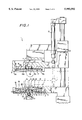
- FIG. 1 is an elevational view partly in section of a preferred embodiment of an apparatus for gluing disc halves together during manufacture of data-storage optical discs in accordance with the teachings of the present invention.
- FIG. 2 is another preferred embodiment of an apparatus for gluing disc halves together during manufacture of data-storage optical discs in accordance with the teachings of the present invention.
- FIG. 3 is yet another preferred embodiment of an apparatus for gluing disc halves together during manufacture of data-storage optical discs in accordance with the teachings of the present invention.
- FIG. 4 diagrammatically shows the structure and operating principle of an optical disc of the "DVD5" type.
- FIG. 5 diagrammatically shows the structure and operating principle of an optical disc of the "DVD10" type
- FIG. 6 diagrammatically shows the structure and operating principle of an optical disc of the "DVD9" type.
- FIG. 1 a device and method for gluing disc halves together during manufacturing of data-storage optical discs in accordance with the teachings of the present invention has been generally identified by reference numeral 1.
- FIGS. 4, 5 and 6 have been provided to illustrate three different kinds of "DVD” discs that can be obtained by the process of the apparatus according to the present invention. More particularly, as is shown in FIG. 4, an optical disc D of the "DVD5" type is illustrated which includes a first disc half 3 on which data is recorded and a second disc half 14 applied to the first disc half 3 for protection of the recorded data.
- the recorded data can be read by a laser head, represented by arrow F in FIG. 4 and operating on the side of the first disc half 3.
- FIG. 5 illustrates an optical disc of the "DVD10"type.
- two disc halves 3, 14 both carry recorded data.
- the recorded data on either disc half 3, 14 can be read by respective playback heads F and Fl disposed on opposite sides respectively relative to disc D.
- FIG. 6 illustrates an optical disc of the "DVD9" type wherein similar to the "DVD10" type disc, both disc halves 3, 14 carry recorded data.
- the recorded data can be read by two respective playback heads F, Fl both disposed on the same side of disc D, as shown in FIG. 6.
- a main support 2 is arranged to receive and support thereon a first disc half 3 which has a surface intended for gluing 3a turned upwardly, in the opposite direction to the main support 2.
- the main support 2 includes an elastic-deformation assembly 4 for disposing the first disc half 3 in a resiliently deformed condition wherein the first disc half has an outer circumferential edge 3b thereof raised relative to its central portion 3c, as is clearly shown in FIGS. 1 to 3.
- the elastic-deformation assembly 4 may include a rest portion 5 formed on a side wall 6 of the main support 2 and shaped as to act on the outer circumferential edge 3b of the first disc half 3.
- This elastic-deformation assembly cooperates and interacts with holding assembly 7, 8, 9 operating on the first disc half to lower the central position 3c thereof so as to bring it to its deformed condition from a rest condition in which it is substantially planar.
- the holding assembly 7, 8, 9 can optionally be of a mechanical type.
- the holding assembly includes one or more suction ducts 7 connected to a vacuum pump (not shown) and opening, through the main support 2, into a vacuum chamber 8 defined between the main support 2 and a lower surface 3d of the first disc half 3.
- the parametric edge 3b of the lower surface of the first disc half 3 is located on the rest portion 5.
- the elastic deformation of the first disc half 3 from its rest condition to a resiliently deformed condition can be achieved by an axial thrust action performed on the disc half.
- This axial thrust action can be achieved by means of a handling device (not shown) which is intended for automatic loading of the disc half 3 onto the main support 2.
- a correct and precise centering of the first disc half 3 may be enhanced by arranging, at the end of the side wall 6 and next to the rest portion 5, at least one parametric centering projection 6a, the shape of which substantially matches that of the disc half.
- One or more suction cups 9 associated at their ends with the suction ducts 7 operate close to the lower surface 3d of the first disc half 3 to conveniently hold it in its deformed condition.
- the first disc half 3 Upon reaching the elastic-deformation condition, the first disc half 3 has its central portion 3c in contact with one or more inner rest elements that can be embodied by the suction cups 9, for example.
- the inner rest elements may be in the form of mechanical abutment shoulders, for instance, formed on a base wall 2a or a central hub 10 carried by the main support 2 for fitting of a central hole usually provided in the first disc half 3.
- the apparatus and method of the present invention further includes an auxiliary support 11 preferably mounted on a guide structure 12 integral with the main support 2, at an opposite position relative to the main support.
- the auxiliary support 11 Upon the action of a fluid-operated actuator 13 or equivalent means, the auxiliary support 11 is movable relative to the main support 2 between a standby position, wherein the auxiliary support 11 is moved away from the main support, as shown by solid line, to receive and engage a second disc half 14, and a work position wherein as shown by chain line in FIG. 1, the auxiliary support 11 acts on the main support 2 to mate the second disc half 14 with the first disc half 3, as better clarified in the following description.
- the auxiliary support 11 In the work position, the auxiliary support 11 is advantageously engaged with the parametric projection 6a of the main support 2, so as to ensure a accurate centering of the second disc half 14 relative to the first disc half 3.
- Positioning of the second disc half 14 under the auxiliary support 11 can be carried out for example by a mechanical handling device.
- a mechanical handling device In order to promote centering of the second disc half 14 during engagement with the auxiliary support 11, use of an outer jacket 15 is provided which is rigidly fixed relative to the guide structure 12.
- the outer jacket 15 surrounds the auxiliary support 11 slightly projecting from a lower edge thereof, so as to define at least one auxiliary projection 15a.
- the shape of the projection 15 substantially matches that of the second disc half 14 and is substantially similar to the parametric projection 6a defined by the side wall 6 of the main support 2.
- the auxiliary support 11 When the auxiliary support 11 is moved away from its standby position, the auxiliary support 11 is released from the outer jacket 15 so that, upon reaching the work position, the auxiliary support 11 can be axially fitted in the parametric projection 6a of the main support 2 thereby bringing the outer circumferential edge 14a of the second disc half 14 in abutment on the outer circumferential edge 3b of the first disc half 3.
- the auxiliary support 11 also includes an auxiliary holding assembly 16 retaining the second disc half 14, once the second disc half 14 has been released under the auxiliary support 11 by the above-mentioned mechanical handling device.
- the auxiliary holding assembly 16 may be of a mechanical type or, as provided in the described embodiment, may include the use of one or more auxiliary suction cups 16a to be actuated through respective suction ducts 17 connected with a suction pump (not shown).
- the auxiliary suction cups 16a hold the second disc half 14, retaining the second disc half 14 in a rest condition, that is, in a substantially planar configuration wherein its circumferential edge 14a abuts against an auxiliary rest portion 18 provided on the auxiliary support 11.
- the auxiliary suction cups 16a take a slightly raised position relative to the lying plane of the auxiliary rest portion 18, so that, together with the rest portion 18, the auxiliary suction cups 16a define auxiliary deformation members similar in structure and operation to the elastic-deformation members described with reference to the main support 2.
- the suction ducts 17 in the embodiments in FIGS. 1 and 2 open through the respective auxiliary suction cups 16a into an auxiliary vacuum chamber 19 defined between the auxiliary support 11 and an upper surface 14b of the second disc half 14.
- the vacuum produced in the auxiliary chamber 19 causes deformation of the second disc half 14 from its rest condition to a respective elastic-deformation condition, wherein the second disc half is deformed into a substantially conical configuration, with a central portion thereof being raised relative to its outer circumferential edge 14a.
- the central portion 14c of the second disc half 14 is brought into abutment relation with one or more auxiliary inner rest elements that may, for example, be in the form of the same auxiliary suction cups 16a.
- the auxiliary suction cups 16a also perform the function of holding the second disc half 14 in its resiliently deformed condition.
- the apparatus for gluing disc halves 1 of the present invention also includes an adhesive dispensing assembly generally referred to by reference numeral 20, adapted to distribute an adhesive or glue between the first and second disc halves 3, 14 so as to enable stable pairing of the first and second disc halves 3, 14.
- the adhesive dispensing assembly 20 includes a delivery nozzle 21 operating at the central portion of the first disc half 3, having its dispensing end extending in the direction of the parametric edge 3b of the latter.
- An actuating member 21a formed of an electric motor, for example, drives nozzle 21 in rotation about the first disc half 3 axis, as shown by arrow A, to evenly spread the adhesive along the outer circumferential edge 3b of the first disc half.
- nozzle 21 preferably operates through a opening 22 concentrically formed through the base wall 2a of the main support 2.
- delivery nozzle 21 and respective actuating member 21a may be in engagement with the auxiliary support 11 as well, in the same manner as above described.
- the electric motor or equivalent actuating member can drive the main support 2 in rotation about its own axis, coincident with the geometric axis of the first disc half 3, as shown by arrow A1 in FIGS. 2 and 3.
- the delivery nozzle 21 is movable, as shown by arrow B, between a rest position, wherein the delivery nozzle 21 is moved away from the main support 2 and the first disc half 3, beyond the radial overall dimensions of same, and an operating position, wherein the delivery nozzle 21 operates close to the outer circumferential edge 3b of the first disc half 3 to evenly distribute the adhesive while the support 2, and as a result the disc half, are being rotated.
- nozzle 21 can be moved in a vertical direction to cause the end of said nozzle to be brought close to the parametric edge 3b extending over the parametric projection 6a without interfering therewith.
- the dispensed adhesive delivered along the circumferential edge 3b of the first disc half 3 preferably has a low viscosity, comparable to that of water. Consequently, due to the invertedcone configuration of the first disc half 3 when disposed in its resiliently deformed condition, the adhesive distributed in a predetermined amount along the outer circumferential edge 3b tends to spread by gravity, thereby being evenly distributed over the entire surface 3a intended for gluing. If required, in the embodiment shown in FIGS. 2 and 3, the delivery nozzle 21 can be actuated above the first disc half 3 even in the direction of the geometric axis of the latter, to facilitate an even glue spreading.
- the first disc 3 is arranged on the main support 2 in such a manner that its surface intended for gluing 3a is turned upwardly.
- the suction action produced in the vacuum chamber 8 causes the elastic deformation of the first disc half 3 from its rest condition, wherein the first disc half is in a substantially planar configuration, to its resiliently deformed condition, wherein the central portion 3c of the disc half is engaged by the suction cups 9.
- the second disc half 14 is also engaged under the auxiliary support 11.
- the second disc half 14 is brought to its respective elastic deformation condition wherein the second disc half 14 is deformed in a substantially conical configuration, in mirror image relationship with the first disc half 3.
- the auxiliary support 11 is lowered onto the main support 2 so that the outer circumferential edge 14a of the second disc half 14 is brought into contact with the outer circumferential edge 3b of the first disc half 3, as shown in broken line of FIG. 1.
- the delivery nozzle 21 is activated and thereby delivers glue at least at the outer circumferential edge 3b of the first disc half 3.
- nozzle 21 is set in rotation by the actuating member 21a so that glue is distributed along the entire extension of the circumferential edge of the disc half 3. Since the circumferential edge 3b of the first disc half 3 is in contact with the circumferential edge 14a of the second disc half 14, any risks of glue escaping from the parametric edges of the disc halves is advantageously eliminated.
- the delivered glue on the periphery of the disc half 3 immediately runs down by gravity towards the central portion 3a of the disc half itself, and evenly spreads over the entire surface to be glued 3a.
- the first and second disc halves 3, 14 are released simultaneously or one after the other from their elastic deformation condition by deactivation of the suction produced through the respective suction ducts 7, 17. Then, the disc halves 3, 14 resiliently resume their respective rest conditions and consequently mate with each other, since the lower surface 14d of the second disc half 14 comes into contact with the gluing surface 3a of the first disc half 3 which is coated with glue. The optical disc thus obtained can thereby be removed from the apparatus 1 after moving the auxiliary support 11 away from the main support 2.
- the operating cycle of the embodiment shown therein shown involves engagement of the first and second disc halves 3, 14 on the main support 2 and auxiliary support 11 respectively, in the same manner as above described with reference to the embodiment of FIG. 1.
- glue is spread on the first disc half 3.
- the delivery nozzle 21 is moved to its operating position, close to the outer circumferential edge 3b of the first disc half 3.
- the main support 2 is rotated in the direction of arrow Al together with the first disc half 3, while the delivery nozzle 21 is delivering glue which is therefore spread on the entire extension of the outer circumferential edge 3b of said disc half.
- the delivery nozzle 21 is then moved from its operating position to its rest position to enable the second disc half 14 to move close to the first disc half 3.
- the disc halves 3, 14 are released from their elastically deformed condition to be matingly paired together in the same manner as described with reference to the embodiment of FIG. 1.
- the arrangement of the first disc half 3 on the main support 2 and elastic deformation thereof occur in the same manner as previously described.
- the second disc half 14 is positioned on the auxiliary support 11 and retained thereon by the holding assembly 16 maintaining a planar configuration.
- glue is spread on the first disc half 3 in the same manner as described with reference to the embodiment of FIG. 2.
- the first disc half 3 When the glue delivered to the outer circumferential edge 3b has been evenly distributed on the gluing surface 3a, the first disc half 3 is released from its deformed condition to a rest condition, achieving a planar configuration again, and after displacement of the delivery nozzle 21 to its rest position, the auxiliary support 11 is lowered onto the main support 2.
- the disc halves 3, 14, both disposed in a rest condition and having therefore a planar configuration mate with each other by direct mutual contact of the entire surface extension of their opposite surfaces 3a, 14d.
- the operating cycle relative to the preferred embodiments described terminate with an optional pressing of the two disc halves 3, 14 followed by a drying step applied to any separation remaining between the two disc halves.
- the apparatus of the present invention is therefore capable of performing mating of the disc halves in an optimal manner, by ensuring an even glue distribution on the surfaces in mutual contact and eliminating any risks of glue escaping from the outer parametric edge of the obtained disc. Thus, any additional cleaning and/or grinding operation is no longer required for eliminating any excess glue extending from the outer parametric edges of the discs.
- the apparatus of the present invention is very simple in terms of achieving its intended goal and operation, which in turn leads to advantages in the manufacturing and servicing costs of same.
- the apparatus in question can be easily installed on conventional machines for automatic production of optical discs.
Landscapes
- Engineering & Computer Science (AREA)
- Mechanical Engineering (AREA)
- Manufacturing & Machinery (AREA)
- Manufacturing Optical Record Carriers (AREA)
- Holo Graphy (AREA)
Applications Claiming Priority (2)
| Application Number | Priority Date | Filing Date | Title |
|---|---|---|---|
| EP97830121A EP0866450B1 (de) | 1997-03-17 | 1997-03-17 | Gerät und Verfahren zum Kleben von Plattenhälften zur Herstellung von optischen Datenspeicherplatten |
| EP97830121 | 1997-03-17 |
Publications (1)
| Publication Number | Publication Date |
|---|---|
| US5993592A true US5993592A (en) | 1999-11-30 |
Family
ID=8230599
Family Applications (1)
| Application Number | Title | Priority Date | Filing Date |
|---|---|---|---|
| US08/996,493 Expired - Fee Related US5993592A (en) | 1997-03-17 | 1997-12-23 | Apparatus and method for gluing disc halves together during manufacturing of data-storage optical discs |
Country Status (5)
| Country | Link |
|---|---|
| US (1) | US5993592A (de) |
| EP (1) | EP0866450B1 (de) |
| AT (1) | ATE181784T1 (de) |
| CA (1) | CA2230413A1 (de) |
| DE (1) | DE69700301T2 (de) |
Cited By (21)
| Publication number | Priority date | Publication date | Assignee | Title |
|---|---|---|---|---|
| US6179031B1 (en) * | 1997-10-08 | 2001-01-30 | Leybold Systems Gmbh | Process for the adhesion of a flat plastic substrate in the form of a circular disk to a like second substrate for a digital video disc and apparatus for implementation of the process |
| US6312549B1 (en) * | 1999-03-10 | 2001-11-06 | Global Machinery Co., Ltd. | Optical disk pasting apparatus and method for pasting optical disks |
| DE10122668C1 (de) * | 2001-05-10 | 2002-10-10 | Steag Hamatech Ag | Vorrichtung zum Verkleben von Substraten |
| EP1253342A1 (de) | 2001-04-23 | 2002-10-30 | New Venture Gear, Inc. | Schaltsteuerungssystem für eine Zweirichtungsfreilaufkupplung |
| EP1253041A2 (de) | 2001-04-27 | 2002-10-30 | New Venture Gear, Inc. | Bedarfsabhängiges Vierradantriebsverteilergetriebe mit steuerbarer Zweirichtungskupplungsanordnung |
| DE10122667C1 (de) * | 2001-05-10 | 2002-11-07 | Steag Hamatech Ag | Vorrichtung zum Verkleben von Substraten |
| US6494511B1 (en) * | 1998-04-24 | 2002-12-17 | Steag Hamatech Ag | Apparatus and method for handling substrates |
| US20030042632A1 (en) * | 2001-08-31 | 2003-03-06 | Noboru Murayama | Plate-like body manufacturing method and apparatus controlling entry of air bubbles |
| US6557680B2 (en) | 2000-07-07 | 2003-05-06 | New Venture Gear, Inc. | On-demand transfer case with integrated sprocket and bi-directional clutch assembly |
| WO2003042564A2 (en) | 2001-11-13 | 2003-05-22 | New Venture Gear, Inc. | Full-time transfer case with synchronized range shift and controllable bi-directional clutch |
| DE10159022A1 (de) * | 2001-11-30 | 2003-06-12 | Krauss Maffei Kunststofftech | Verfahren zum Herstellen eines Datenträgers aus zwei Halbseiten |
| US6602159B1 (en) | 2002-02-05 | 2003-08-05 | New Venture Gear, Inc. | On-demand transfer case with integrated sprocket and bi-directional clutch assembly |
| US6612957B2 (en) | 2001-03-27 | 2003-09-02 | New Venture Gear, Inc. | Hydraulic shift transfer case with band brake and bi-directional clutch |
| US6770162B2 (en) * | 2000-09-28 | 2004-08-03 | Pioneer Corporation | Method of manufacturing a disk and transfer method for the disk |
| US20040220010A1 (en) * | 2002-02-05 | 2004-11-04 | Williams Randolph C. | Transfer case with a tri-mode bi-directional clutch assembly |
| US20050202918A1 (en) * | 2004-03-15 | 2005-09-15 | Richard Mizon | On-demand power take-off unit for four-wheel drive vehicle |
| US20050215376A1 (en) * | 2004-03-29 | 2005-09-29 | Williams Randolph C | Torque coupling with tri-mode overrunning clutch assembly |
| US20170368763A1 (en) * | 2016-06-28 | 2017-12-28 | Ford Motor Company | Applicator and Method for Applying a Lubricant/Sealer |
| US10265814B2 (en) | 2016-06-28 | 2019-04-23 | Ford Motor Company | Flexible pressing system |
| US10534350B2 (en) | 2016-06-28 | 2020-01-14 | Ford Motor Company | Flexible pressing verification system |
| US11020830B2 (en) | 2014-02-26 | 2021-06-01 | Ford Global Technologies, Llc | System, method and tooling for flexible assembly of cylinder-head valve trains |
Families Citing this family (5)
| Publication number | Priority date | Publication date | Assignee | Title |
|---|---|---|---|---|
| ATE232162T1 (de) * | 1997-11-12 | 2003-02-15 | Steag Hamatech Inc | System und verfahren zum anbringen eines harzes zwischen den substraten einer verbunddatenspeicherplatte |
| US6106657A (en) * | 1998-05-19 | 2000-08-22 | First Light Technology, Inc. | System and method for dispensing a resin between substrates of a bonded storage disk |
| EP1164004A3 (de) * | 1997-11-12 | 2005-01-26 | STEAG HamaTech, Inc. | System und Verfahren zum anbringen eines Harzes zwischen den Substraten einer Verbunddatenspeicherplatte |
| JPH11283279A (ja) * | 1998-01-30 | 1999-10-15 | Minnesota Mining & Mfg Co <3M> | 貼り合わせ型光ディスク並びにその製造方法及び装置 |
| JP4777067B2 (ja) * | 2003-08-22 | 2011-09-21 | ジングルス・テヒノロギース・アクチェンゲゼルシャフト | ディスク状基板の結合のための方法およびこの方法を実行するための装置 |
Citations (5)
| Publication number | Priority date | Publication date | Assignee | Title |
|---|---|---|---|---|
| US5284538A (en) * | 1990-02-22 | 1994-02-08 | Sony Corporation | Optical disc having signal recording layer on each side and method for producing same |
| US5318653A (en) * | 1989-03-27 | 1994-06-07 | Mitsubishi Denki Kabushiki Kaisha | Optical disc and method and apparatus for making same |
| US5744193A (en) * | 1995-05-20 | 1998-04-28 | Kitano Engineering Co., Ltd. | Method of manufacturing an optical disc and a placing platform to be used by the same |
| US5800670A (en) * | 1995-05-20 | 1998-09-01 | Kitano Engineering Co., Ltd. | Spreader of an optical disc |
| US5882555A (en) * | 1995-11-22 | 1999-03-16 | Discart, Inc | Apparatus and method for manufacturing compact discs having a non-round outer profile |
Family Cites Families (2)
| Publication number | Priority date | Publication date | Assignee | Title |
|---|---|---|---|---|
| JPH02308444A (ja) * | 1989-05-23 | 1990-12-21 | Seiko Epson Corp | 光記録媒体の製造方法 |
| JP3498816B2 (ja) * | 1995-04-20 | 2004-02-23 | 日本政策投資銀行 | 光ディスクの製造方法 |
-
1997
- 1997-03-17 DE DE69700301T patent/DE69700301T2/de not_active Expired - Fee Related
- 1997-03-17 EP EP97830121A patent/EP0866450B1/de not_active Expired - Lifetime
- 1997-03-17 AT AT97830121T patent/ATE181784T1/de active
- 1997-12-23 US US08/996,493 patent/US5993592A/en not_active Expired - Fee Related
-
1998
- 1998-02-25 CA CA002230413A patent/CA2230413A1/en not_active Abandoned
Patent Citations (5)
| Publication number | Priority date | Publication date | Assignee | Title |
|---|---|---|---|---|
| US5318653A (en) * | 1989-03-27 | 1994-06-07 | Mitsubishi Denki Kabushiki Kaisha | Optical disc and method and apparatus for making same |
| US5284538A (en) * | 1990-02-22 | 1994-02-08 | Sony Corporation | Optical disc having signal recording layer on each side and method for producing same |
| US5744193A (en) * | 1995-05-20 | 1998-04-28 | Kitano Engineering Co., Ltd. | Method of manufacturing an optical disc and a placing platform to be used by the same |
| US5800670A (en) * | 1995-05-20 | 1998-09-01 | Kitano Engineering Co., Ltd. | Spreader of an optical disc |
| US5882555A (en) * | 1995-11-22 | 1999-03-16 | Discart, Inc | Apparatus and method for manufacturing compact discs having a non-round outer profile |
Cited By (42)
| Publication number | Priority date | Publication date | Assignee | Title |
|---|---|---|---|---|
| US6179031B1 (en) * | 1997-10-08 | 2001-01-30 | Leybold Systems Gmbh | Process for the adhesion of a flat plastic substrate in the form of a circular disk to a like second substrate for a digital video disc and apparatus for implementation of the process |
| US6494511B1 (en) * | 1998-04-24 | 2002-12-17 | Steag Hamatech Ag | Apparatus and method for handling substrates |
| US6312549B1 (en) * | 1999-03-10 | 2001-11-06 | Global Machinery Co., Ltd. | Optical disk pasting apparatus and method for pasting optical disks |
| US6557680B2 (en) | 2000-07-07 | 2003-05-06 | New Venture Gear, Inc. | On-demand transfer case with integrated sprocket and bi-directional clutch assembly |
| US6770162B2 (en) * | 2000-09-28 | 2004-08-03 | Pioneer Corporation | Method of manufacturing a disk and transfer method for the disk |
| US6612957B2 (en) | 2001-03-27 | 2003-09-02 | New Venture Gear, Inc. | Hydraulic shift transfer case with band brake and bi-directional clutch |
| EP1253342A1 (de) | 2001-04-23 | 2002-10-30 | New Venture Gear, Inc. | Schaltsteuerungssystem für eine Zweirichtungsfreilaufkupplung |
| US6846262B2 (en) | 2001-04-23 | 2005-01-25 | New Venture Gear, Inc. | Transfer case shift system for controllable bi-directional overrunning clutch |
| US20040106489A1 (en) * | 2001-04-23 | 2004-06-03 | Williams Randolph C. | Transfer case shift system for controllable bi-directional overrunning clutch |
| US6652407B2 (en) | 2001-04-23 | 2003-11-25 | New Venture Gear, Inc. | Transfer case shift system for controllable bi-directional overrunning clutch |
| US6805652B2 (en) | 2001-04-27 | 2004-10-19 | New Venture Gear, Inc. | On-demand transfer case with controllable bi-directional overrunning clutch assembly |
| US20040168545A1 (en) * | 2001-04-27 | 2004-09-02 | Fitzgerald Brian M. | Modular bi-directional clutch assembly |
| EP1253041A2 (de) | 2001-04-27 | 2002-10-30 | New Venture Gear, Inc. | Bedarfsabhängiges Vierradantriebsverteilergetriebe mit steuerbarer Zweirichtungskupplungsanordnung |
| US6862953B2 (en) | 2001-04-27 | 2005-03-08 | Magna Drivetrain Of America, Inc. | Modular bi-directional clutch assembly |
| US6629474B2 (en) | 2001-04-27 | 2003-10-07 | New Venture Gear, Inc. | On-demand transfer case with controllable bi-directional overrunning clutch assembly |
| DE10122667C1 (de) * | 2001-05-10 | 2002-11-07 | Steag Hamatech Ag | Vorrichtung zum Verkleben von Substraten |
| US20040149376A1 (en) * | 2001-05-10 | 2004-08-05 | Stephan Leonhardt | Device for bonding substrates |
| DE10122668C1 (de) * | 2001-05-10 | 2002-10-10 | Steag Hamatech Ag | Vorrichtung zum Verkleben von Substraten |
| US7044185B2 (en) * | 2001-08-31 | 2006-05-16 | Ricoh Company, Ltd. | Plate-like body manufacturing method and apparatus controlling entry of air bubbles |
| US20060162856A1 (en) * | 2001-08-31 | 2006-07-27 | Noboru Murayama | Plate-like body manufacturing method and apparatus controlling entry of air bubbles |
| US20030042632A1 (en) * | 2001-08-31 | 2003-03-06 | Noboru Murayama | Plate-like body manufacturing method and apparatus controlling entry of air bubbles |
| WO2003042564A2 (en) | 2001-11-13 | 2003-05-22 | New Venture Gear, Inc. | Full-time transfer case with synchronized range shift and controllable bi-directional clutch |
| DE10159022A1 (de) * | 2001-11-30 | 2003-06-12 | Krauss Maffei Kunststofftech | Verfahren zum Herstellen eines Datenträgers aus zwei Halbseiten |
| US6974400B2 (en) | 2002-02-05 | 2005-12-13 | American Axle & Manufacturing, Inc. | Transfer case with a tri-mode bi-directional clutch assembly |
| US6878088B2 (en) | 2002-02-05 | 2005-04-12 | Magna Drivetrain Of America, Inc. | On-demand transfer case with bi-directional clutch assembly |
| US20040220010A1 (en) * | 2002-02-05 | 2004-11-04 | Williams Randolph C. | Transfer case with a tri-mode bi-directional clutch assembly |
| US6602159B1 (en) | 2002-02-05 | 2003-08-05 | New Venture Gear, Inc. | On-demand transfer case with integrated sprocket and bi-directional clutch assembly |
| US20030232690A1 (en) * | 2002-02-05 | 2003-12-18 | Williams Randolph C. | On-demand transfer case with bi-directional clutch assembly |
| US7150694B2 (en) | 2004-03-15 | 2006-12-19 | Magna Powertrain Usa, Inc. | Power take-off unit for four-wheel drive vehicle |
| WO2005089280A2 (en) | 2004-03-15 | 2005-09-29 | Magna Powertrain Usa, Inc. | On-demand power take-off unit for four-wheel drive vehicle |
| US20050202918A1 (en) * | 2004-03-15 | 2005-09-15 | Richard Mizon | On-demand power take-off unit for four-wheel drive vehicle |
| US20060094556A1 (en) * | 2004-03-15 | 2006-05-04 | Magna Powertrain, Inc. | Power take-off unit for four-wheel drive vehicle |
| US7004874B2 (en) | 2004-03-15 | 2006-02-28 | Magna Powertrain, Inc. | On-demand power take-off unit for four-wheel drive vehicle |
| US20050215376A1 (en) * | 2004-03-29 | 2005-09-29 | Williams Randolph C | Torque coupling with tri-mode overrunning clutch assembly |
| US20060142109A1 (en) * | 2004-03-29 | 2006-06-29 | Magna Powertrain, Inc. | Power transfer device with overrunning mode clutch |
| US7004875B2 (en) | 2004-03-29 | 2006-02-28 | Magna Powertrain, Inc. | Torque coupling with tri-mode overrunning clutch assembly |
| US7278946B2 (en) | 2004-03-29 | 2007-10-09 | Magna Powertrain Usa, Inc. | Power transfer device with overrunning mode clutch |
| US11020830B2 (en) | 2014-02-26 | 2021-06-01 | Ford Global Technologies, Llc | System, method and tooling for flexible assembly of cylinder-head valve trains |
| US20170368763A1 (en) * | 2016-06-28 | 2017-12-28 | Ford Motor Company | Applicator and Method for Applying a Lubricant/Sealer |
| US10265814B2 (en) | 2016-06-28 | 2019-04-23 | Ford Motor Company | Flexible pressing system |
| US10534350B2 (en) | 2016-06-28 | 2020-01-14 | Ford Motor Company | Flexible pressing verification system |
| US11383452B2 (en) | 2016-06-28 | 2022-07-12 | Ford Motor Company | Applicator and method for applying a lubricant/sealer |
Also Published As
| Publication number | Publication date |
|---|---|
| EP0866450B1 (de) | 1999-06-30 |
| DE69700301D1 (de) | 1999-08-05 |
| ATE181784T1 (de) | 1999-07-15 |
| EP0866450A1 (de) | 1998-09-23 |
| CA2230413A1 (en) | 1998-09-17 |
| DE69700301T2 (de) | 1999-11-04 |
Similar Documents
| Publication | Publication Date | Title |
|---|---|---|
| US5993592A (en) | Apparatus and method for gluing disc halves together during manufacturing of data-storage optical discs | |
| KR100529437B1 (ko) | 디스크 유지 장치 | |
| JPH0276182A (ja) | ディスクカートリッジ | |
| US6714507B2 (en) | Disc device | |
| EP0087913B1 (de) | Bandkassette | |
| EP1306838B1 (de) | Plattenhaltevorrichtung | |
| JP3703230B2 (ja) | 保持台から記憶ディスクを取り上げる方法 | |
| US4752847A (en) | Storage disk drive mechanism | |
| US4430678A (en) | Drive apparatus for recording disks in which the disk is clamped between a driven recessed member and a rotatably mounted clamping member | |
| US7563402B2 (en) | Apparatus for and method of manufacturing an optical disc | |
| JP3477284B2 (ja) | 光デイスクの製造方法及び装置 | |
| JP3094495B2 (ja) | ディスククランプ装置 | |
| JP3628816B2 (ja) | 記憶ディスクの保持台及びそのボス体 | |
| JPH0648549B2 (ja) | デイスク保持装置 | |
| JPS6312424Y2 (de) | ||
| JP2000339921A (ja) | ターンテーブル及びその製造方法並びにディスク駆動装置 | |
| JP2600155B2 (ja) | デイスク装着装置 | |
| JP3747553B2 (ja) | ディスク状記録媒体のチャッキング装置 | |
| JPH10199083A (ja) | ディスククランプ装置 | |
| JP2006252623A (ja) | 記録ディスク載置装置、記録ディスク駆動用モータおよび記録ディスク装置 | |
| US20040173321A1 (en) | Device for bonding substrates | |
| JP2000306303A (ja) | ディスク装置 | |
| JPH10134423A (ja) | 保持台からの記憶ディスクの取り上げ方法及びその装置 | |
| JP2001195819A (ja) | ディスク再生装置 | |
| JPH02118952A (ja) | ディスク装着装置 |
Legal Events
| Date | Code | Title | Description |
|---|---|---|---|
| AS | Assignment |
Owner name: TAPEMATIC USA INC., FLORIDA Free format text: ASSIGNMENT OF ASSIGNORS INTEREST;ASSIGNOR:PEREGO, LUCIANO;REEL/FRAME:010057/0435 Effective date: 19990616 |
|
| REMI | Maintenance fee reminder mailed | ||
| LAPS | Lapse for failure to pay maintenance fees | ||
| FP | Lapsed due to failure to pay maintenance fee |
Effective date: 20031130 |
|
| STCH | Information on status: patent discontinuation |
Free format text: PATENT EXPIRED DUE TO NONPAYMENT OF MAINTENANCE FEES UNDER 37 CFR 1.362 |