US6033127A - Camera - Google Patents
Camera Download PDFInfo
- Publication number
- US6033127A US6033127A US09/074,362 US7436298A US6033127A US 6033127 A US6033127 A US 6033127A US 7436298 A US7436298 A US 7436298A US 6033127 A US6033127 A US 6033127A
- Authority
- US
- United States
- Prior art keywords
- film cartridge
- film
- operating
- operating lever
- gear
- Prior art date
- Legal status (The legal status is an assumption and is not a legal conclusion. Google has not performed a legal analysis and makes no representation as to the accuracy of the status listed.)
- Expired - Fee Related
Links
- 238000004804 winding Methods 0.000 claims abstract description 78
- 230000033001 locomotion Effects 0.000 claims abstract description 44
- 230000001105 regulatory effect Effects 0.000 description 22
- 238000010276 construction Methods 0.000 description 3
- 238000004519 manufacturing process Methods 0.000 description 2
- 230000002093 peripheral effect Effects 0.000 description 2
- 230000005540 biological transmission Effects 0.000 description 1
- 238000006073 displacement reaction Methods 0.000 description 1
- 230000008676 import Effects 0.000 description 1
- 230000037431 insertion Effects 0.000 description 1
- 238000003780 insertion Methods 0.000 description 1
Images


Classifications
-
- G—PHYSICS
- G03—PHOTOGRAPHY; CINEMATOGRAPHY; ANALOGOUS TECHNIQUES USING WAVES OTHER THAN OPTICAL WAVES; ELECTROGRAPHY; HOLOGRAPHY
- G03B—APPARATUS OR ARRANGEMENTS FOR TAKING PHOTOGRAPHS OR FOR PROJECTING OR VIEWING THEM; APPARATUS OR ARRANGEMENTS EMPLOYING ANALOGOUS TECHNIQUES USING WAVES OTHER THAN OPTICAL WAVES; ACCESSORIES THEREFOR
- G03B17/00—Details of cameras or camera bodies; Accessories therefor
- G03B17/42—Interlocking between shutter operation and advance of film or change of plate or cut-film
-
- G—PHYSICS
- G03—PHOTOGRAPHY; CINEMATOGRAPHY; ANALOGOUS TECHNIQUES USING WAVES OTHER THAN OPTICAL WAVES; ELECTROGRAPHY; HOLOGRAPHY
- G03B—APPARATUS OR ARRANGEMENTS FOR TAKING PHOTOGRAPHS OR FOR PROJECTING OR VIEWING THEM; APPARATUS OR ARRANGEMENTS EMPLOYING ANALOGOUS TECHNIQUES USING WAVES OTHER THAN OPTICAL WAVES; ACCESSORIES THEREFOR
- G03B2217/00—Details of cameras or camera bodies; Accessories therefor
- G03B2217/26—Holders for containing light-sensitive material and adapted to be inserted within the camera
- G03B2217/266—Thrust-type cartridges
-
- G—PHYSICS
- G03—PHOTOGRAPHY; CINEMATOGRAPHY; ANALOGOUS TECHNIQUES USING WAVES OTHER THAN OPTICAL WAVES; ELECTROGRAPHY; HOLOGRAPHY
- G03B—APPARATUS OR ARRANGEMENTS FOR TAKING PHOTOGRAPHS OR FOR PROJECTING OR VIEWING THEM; APPARATUS OR ARRANGEMENTS EMPLOYING ANALOGOUS TECHNIQUES USING WAVES OTHER THAN OPTICAL WAVES; ACCESSORIES THEREFOR
- G03B2219/00—Cameras
- G03B2219/02—Still-picture cameras
- G03B2219/04—Roll-film cameras
- G03B2219/045—Roll-film cameras adapted for unloading the film in the processing laboratory, e.g. disposable, reusable or recyclable cameras
Definitions
- the present invention relates to a camera and, more particularly, to a camera which is economical to manufacture and in which a film is manually wound and rewound and a used state of the film is displayed in a film cartridge, i.e., an advanced photo system (hereafter referred to as APS) film is used.
- APS advanced photo system
- a film with a lens in which a film is manually wound (e.g., does not automatically wind the film using a motor) and which does not have an automatic focusing system.
- This type of camera is generally known as a throwaway or disposable camera and has a function of rewinding a previously wound film one frame at a time by means of a rewinding knob in order to simplify the winding mechanism.
- a winding knob and a rewinding knob have been independently provided.
- operations such as winding and rewinding of the film and switching of a display showing the used state of the film in a cartridge have been performed by a motor powered by means of a battery.
- Conventional cameras in which the film is wound and rewound by a motor generally have an aesthetic external appearance since it is not necessary to provide a winding knob and a rewinding knob on an outer frame of the camera. Furthermore, in conventional disposable cameras, since it is not necessary to replace the film, it suffices if only the rewinding knob is provided. However, in conventional cameras in which the film can be replaced and operations such as winding of the film are performed manually, a winding knob and a rewinding knob have been independently provided, so that the external appearance of the camera has not been aesthetic. Furthermore, although conventional disposable cameras have a simple structure, wasteful consumption has been promoted with respect to this type of camera since parts which may be still be used are discarded.
- the camera of the present invention has one knob which is used for winding and rewinding the film by a rotating direction regulating member. According to the present invention, after the rewinding operation becomes an operating state of the camera, an exposure of the film can not be performed unless that operating state is released when removing a film cartridge. Furthermore, when a locking operation of a cover member of the camera after loading the film and a lock releasing operation of the cover member when removing the film are performed manually, a display of a used or exposed state of the film in the film cartridge is switched in accordance with these operations.
- the invention provides a camera which uses a film cartridge having a mark for indicating a used state of the film housed therein and which has a mechanism for manually winding and rewinding the film.
- the mechanism comprises a winding knob, a rotating direction regulating member and a regulating member drive portion for driving the rotating direction regulating member.
- the winding knob When the rotating direction regulating member is disposed at a second position by the regulating member drive portion, the winding knob can be rotated only in a reverse direction or a second direction opposite to the first direction, and the rotation of the winding knob in the reverse direction is not transmitted to the winding shaft, so that a rewinding of the film is performed by the rotation of the winding knob in the reverse direction.
- the camera according to the present invention further comprises an operating lever for locking a cover member of a housing portion of the film cartridge, and a mechanism disposed between the regulating member drive portion and the operating lever for maintaining an operating state of the regulating member drive portion.
- the mechanism for maintaining the operating state of the regulating member drive portion is released by pivotal movement of the operating lever.
- the camera according to the present invention further comprises a rotating gear for rotating a film shaft disposed in the film cartridge, a drive gear for opening and closing a shading cover in the film cartridge, and a wheel train having a clutch mechanism for transmitting a pivoting motion of the operating lever to the rotating gear and the drive gear.
- the clutch mechanism is engaged by pivoting the operating lever in a first direction, thereby rotating the rotating gear so that a predetermined used state of the film is displayed by the mark in the film cartridge and rotating the drive gear so as to close the shading cover.
- the clutch mechanism is disengaged by pivoting the operating lever in a reverse direction or a second direction opposite the first direction, thereby making the rotating gear non-rotatable and rotating the drive gear in the reverse direction so as to open the shading cover.
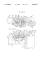
- FIG. 1 is a plan view showing a main portion of an embodiment of a camera according to the present invention
- FIG. 2 is a front view of FIG. 1;
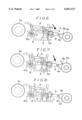
- FIG. 3 is a reduced plan view showing a wheel train for winding and rewinding a film
- FIG. 4 is a plan view showing a state in which a rewinding button for rewinding a film is slightly pressed;
- FIG. 5 is a plan view showing an operating state in which the rewinding button is completely pressed from the state shown in FIG. 4;
- FIG. 6 is a plan view showing a state in which an operating lever is slightly pivoted in order to return the rewinding button
- FIG. 7 is a plan view showing a state in which the operating lever is further pivoted from the state shown in FIG. 6;
- FIG. 8 is a plan view showing a state in which the operating lever is completely pivoted and the rewinding button is returned to a non-operating state
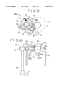
- FIG. 9 is a plan view of a mechanism for closing a shading cover and a mechanism for displaying a used state mark in accordance with the invention.
- FIG. 10 is a front view of FIG. 9;
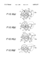
- FIGS. 11(a) to 11(d) are plan views showing an operation when taking out a film cartridge in stages
- FIG. 12 is a perspective view showing a bottom portion of a camera according to the present invention.
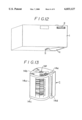
- FIG. 13 is a perspective view showing the film cartridge
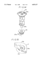
- FIG. 14 is an exploded perspective view showing a structure of an inner portion of the film cartridge
- FIG. 15 is a bottom view of the film cartridge.
- FIGS. 16(a) and 16(b) are plan views showing an operation of loading a film in stages.
- FIGS. 1-16 show an embodiment of the structure of the camera according to the present invention where a camera case 1 has a center plate la for supporting the following structure of the camera described below.
- a film cartridge C is inserted into a film cartridge chamber or film cartridge housing portion 1b (FIG. 10) disposed within the case 1 by opening a cover member 1c (FIG. 12) disposed at a lower side of the case 1.
- a film F is drawn from a slit 14d (FIG. 13) formed on a side surface of the film cartridge C, and a photographing operation is performed one frame at a time.
- An operating member comprising a winding knob 2 is rotatably disposed at the right side of the camera in FIG.
- a tooth portion 2a disposed on an outer periphery of the winding knob 2 projects slightly from an upper portion of a rear surface of the case 1 (FIG. 12) so that a user can operate it manually.
- a rotating winding member in the form of a winding shaft 3 is disposed at the left side in FIG. 1. Rotation of the winding knob 2 is transmitted to the winding shaft 3 through a driving mechanism comprising a transmitting wheel train W1 shown in FIG. 3.
- a gear 3a is mounted at an end portion of the winding shaft 3 in coaxial relation therewith.
- the reverse rotation preventing lever 4 is pivotally supported by a pin 4c disposed on the center plate 1a in perpendicular relation thereto.
- a connecting groove portion 4d is provided at a second end portion of the reverse rotation preventing lever 4 opposite the first end portion.
- a rewinding button 5 defines a drive member or regulating member drive portion for driving the reverse rotation preventing lever 4.
- An end portion (refer to a lower end portion in FIG. 1) of the rewinding button 5 is exposed from the case 1 and can be operated by a user.
- a connecting pin 5a projects beyond an upper surface of the rewinding button 5 and is fitted into the connecting groove portion 4d of the reverse rotation preventing lever 4, thereby transmitting the motion or displacement of the rewinding button 5 to the reverse rotation preventing lever 4.
- an arm 5b, an arm 5c and an elastically engaging arm 5d extend from the rewinding button 5 in a leftward direction, in an upper direction and in a rightward direction, respectively.
- a release lever 6 is disposed at an upper position of the rewinding button 5 as shown in FIG. 1.
- the release lever 6 is adapted such that a pressing motion of a release button (not shown) is transmitted to a front end of an arm 6a extending upwardly from a right end portion in FIG. 1.
- the release lever 6 is supported for pivotal movement by a shaft 6c provided on a front end lower surface of an arm 6b extending in perpendicular relation thereto.
- a biasing member or spring 7 is wound around the shaft 6c, and a counterclockwise urging force is applied to the release lever 6 by the spring 7.
- a pin 6d is disposed on an upper surface of the release lever 6 in the vicinity of a base portion of the arm 6b for engagement with a tapered end surface disposed on a front end of the arm 5c of the rewinding button 5.
- a pawl-like projecting portion 6e extends downwardly from an intermediate portion of the release lever 6.
- a projecting piece 6f projects downwardly on a left side of the projecting portion 6e.
- An engaging pawl 6g is disposed on a left end portion of the release lever 6 for engagement with the gear 3a of the winding shaft 3.
- a shutter lever 8 is disposed on a left side of the rewinding button 5.
- the shutter lever 8 is supported for pivotal movement by a shaft 8a extending generally perpendicular from a lower surface thereof.
- a spring 9 is wound around the shaft 8a and applies a biasing force to the shutter lever 8 in a clockwise direction as shown in FIG. 1.
- a front end portion of an arm 8b extends to an upper portion of the shutter lever 8 and defines a shutter drive portion 8c.
- An engaging projection 8d projects upwardly from an upper surface of the shutter lever 8 at an intermediate portion of the arm 8b and is engageable with the projecting portion 6e of the release lever 6.
- An arm 8e of the shutter lever 8 extends in the rightward direction in FIG. 1 and has a front end for engagement with the arm 5b of the rewinding button 5.
- An arm 8f extends in a leftward direction in FIG. 1 from a base portion of the shutter lever 8.
- a shaft 10 is rotatably supported at a left portion of the shutter lever 8, and a sprocket wheel 10a having sprocket teeth 10a1 for engaging with perforations of a film F is connected to a lower end portion of the shaft 10.
- a cam 10b is provided at an intermediate portion of the shaft 10.
- the cam 10b has three cam surfaces disposed at equal intervals and curving smoothly toward an outer periphery thereof.
- the arm 8f of the shutter lever 8 is engageable with each of the cam surfaces of the cam 10b.
- Another cam 10c is provided on the cam 10b and has three fan-like cam surfaces positioned around the shaft 10 at predetermined gaps.
- a front end of the projecting piece 6f of the release lever 6 can be elastically contacted with the fan-like cam surfaces 10c and the gaps between the fan-like cam surfaces 10c.
- An operating lever 11 for locking the cover member 1c of the film cartridge housing portion 1b is provided on a bottom surface of the camera case 1 and projects outwardly therefrom.
- a shaft 12 is integrally connected to the operating lever 11, defining a pivoting center for the operating lever 11, and extends toward an upper surface of the case 1.
- a gear 13 is fixed to a projecting end of the shaft 12. The gear 13 is provided so as to display that the used state mark of the film is a state in which a photographing operation has already been performed when removing the film cartridge C from the camera, and to drive a wheel train W2 for closing a shading cover of the film F by pivoting the operating lever 11.
- the driving operation of the wheel train W2 will be described later in detail with reference to FIGS. 9-10.
- a mechanism for maintaining the operating state of the rewinding button 5 is disposed between the shaft 12 and the rewinding button 5.
- the operating state of the rewinding button 5 means a state in which the rewinding button 5 is pressed and a rewinding motion of the film F is performed.
- the non-operating state of the rewinding button 5 means a state in which the rewinding button is not pressed and a winding operation of the film is performed.
- the mechanism for maintaining the operating state of the rewinding button 5 comprises an engaging portion 12a disposed on an upper end portion of the shaft 12 for engagement with a front end of the elastically engaging arm 5d of the rewinding button 5 to maintain the rewinding button 5 in a pressed state.
- FIG. 3 An embodiment of the wheel train W1 for winding the film F is shown in FIG. 3.
- the wheel train W1 extends from a gear 20 of the winding knob 2 to the gear 3a of the rewinding shaft 3.
- the wheel train W1 comprises a gear 21 for rotating a film shaft 24 of the film cartridge C (FIG. 14), switching means 22 for switching the rotating direction of the gear 21 between a normal direction and a reverse direction, and clutch means 23 for interrupting the transmission of the rotation to the gear 3a of the rewinding shaft 3.
- the switching means 22 comprises two arms 22a, 22b supported for pivotal movement on a center shaft 22c of a center gear 22d, and pinions 22e, 22f rotatably supported by shafts 22g, 22h at a front end of each of the arms 22a, 22b, respectively.
- the pinions 22e, 22f are always meshed with the center gear 22d, and the pinion to be meshed with the gear 21 is switched in accordance with the rotating direction of the center gear 22d.
- the center gear 22d rotates clockwise
- the pinion 22e rotates counterclockwise and is meshed with the gear 21 so that a clockwise rotation is transmitted to the gear 21.
- the clutch means 23 comprises an arm 23a supported for pivotal movement on a center shaft 23b of a center gear 23c, and a pinion 23d rotatably supported by a shaft 23e at a front end of the arm 23a.
- the pinion 23d is always meshed with the center gear 23c, and rotation of the pinion 23d is transmitted to the gear 3a of the winding shaft 3 through another gear in the wheel train, thereby rotating the winding shaft 3 clockwise when winding the film.
- a wheel train W2 for displaying the used or exposed state mark for the film as a photographed state during removal of the film cartridge C and for closing the shading cover in the film cartridge C is disposed on an upper surface of the housing portion 1b.
- the wheel train W2 comprises a rotating gear 15 for rotating the film shaft 24 of the film cartridge C, a drive gear 16, a drive shaft 16a for opening and closing the shading cover of the film cartridge C, a gear 17, and a clutch mechanism extending from the gear 17 to the rotating gear 15.
- the rotating gear 15 has a shaft portion 15a having a small diameter and being disposed at a lower end of the rotating gear 15 for integral connection to the film shaft 24 of the film cartridge C, a tooth portion 15b formed at an intermediate portion thereof, and a projection 15c projecting outwardly from an upper portion thereof.
- the shaft portion 15a has a protrusion 15a1 for engagement with a groove portion 24c disposed in the film shaft 24 of the film cartridge C (FIG. 15).
- the cover member 1c for opening and closing the housing portion 1b is disposed on a bottom surface of the camera case 1 (FIG. 12) and permits insertion and removal of the film cartridge C into or from the housing portion 1b.
- the operating lever 11 for locking the cover member is disposed adjacent to the cover member 1c.
- the operating lever 11 is integrally connected to the shaft 12 for undergoing pivotal movement.
- the shaft 12 extends to an upper surface of the housing portion 1b, and the gear 13 is fixed to an upper end portion of the shaft 12.
- the drive shaft 16a for opening and closing the shading cover of the film cartridge C is rotatably provided on the upper surface of the housing portion 1b.
- the drive gear 16 is integrally connected to an upper end portion of the drive shaft 16a and is in meshing engagement with the gear 13.
- the gear 17 is rotatably supported by a shaft on an upper surface of the housing portion 1b.
- a pinion 17a is integrally connected to a lower surface of the gear 17 and is in meshing engagement with the gear 13.
- the clutch mechanism comprises a clutch lever 18 frictionally connected to an upper surface of the gear 17, a projection 18a disposed at a front end portion of the clutch lever 18 for engagement with the projection 15c of the rotating gear 15, and a clutch gear 19 rotatably provided on a lower surface of the front end portion of the clutch lever 18.
- the clutch gear 19 is always in meshing engagement with the gear 17, and can be meshed with the tooth portion 15b of the rotating gear 15 by pivoting the clutch lever 18.
- a pin 17b projects from an upper surface of the gear 17 for engagement with the clutch lever 18.
- the pivoting range of the clutch mechanism is regulated by regulating means (not shown) and, for example, it is regulated to an extent of about 10 degrees of a center angle in a clockwise direction from the position shown in FIG. 9. Accordingly, the clutch lever 18 is pivotable only between the regulating means and the pin 17b.
- the film cartridge C comprises a cartridge for an APS film and has a cartridge case 14a having a generally cylindrical shape, an upper cover 14b and a lower cover 14c.
- a slit 14d is provided in a part of the cartridge case 14a for drawing out the film, and a shading cover (not shown) is disposed within the slit 14d.
- the drive shaft 16a of the wheel train W2 is inserted through a through-hole 14e disposed between the upper cover 14b and the lower cover 14c for opening and closing the shading cover.
- a through-hole 14f is disposed in a center portion of the case 14a, and a shaft hole 24a of the film shaft 24 shown in FIG.
- the shaft portion 15a of the rotating gear 15 is inserted into the shaft hole 24a for rotating the film shaft 24 to thereby perform the film winding and rewinding operations.
- a shaft portion 24b extends downwardly from a lower end portion of the film shaft 24, and a display member 25 is integrally connected to the shaft portion 24b.
- the display member 25 is adapted to display outside of the film cartridge C the used state of the film which is wound around the film shaft 24.
- the tongue piece 25a is integrally connected to the display member 25 so as to project outwardly therefrom.
- the film cartridge C is provided with marks for displaying the used state of the film by means of window holes [1] to [4] formed in the case 14a.
- the state shown in FIG. 15 is a state in which the tongue piece 25a exists at a position facing the window hole [1], and the window hole [1] is displayed to be white representing that the film has not been used. Since the tongue piece 25a is integrally connected to the film shaft 24, when the film is wound or rewound the film shaft 24 rotates and the tongue piece 25a is rotated as well, so that the tongue piece 25a is repeatedly moved to the positions facing the window holes [4], [3], [2], [1] . . . from the position facing the window hole [1].
- FIG. 9 displays a state in which the shading cover of the film cartridge C is opened and the photographing operation is performed while winding the film within the film cartridge C.
- the clutch gear 19 of the clutch mechanism and the tooth portion 15b of the rotating gear 15 are not meshed with each other, and the rotating gear 15 can rotate freely so that the film can be wound and rewound by means of the knob 2.
- the tongue piece 25a automatically faces the window hole representing the photographed or used state of the film only by pivoting the operating lever 11.
- the used state of the film is effectively displayed and can be readily recognized by the user and the film cartridge C can be removed from the camera without error.
- FIGS. 16(a) and 16(b) show an operation for loading a new film cartridge C into the camera.
- the gear 17 starts to rotate clockwise through the gear 13 and the pinion 17a, and the clutch lever 18 frictionally follows rotation of the gear 17 so as to pivot clockwise, thereby releasing engagement between the tooth portion 15b of the rotation gear 15 and the clutch gear 19.
- the drive gear 16 rotates clockwise interlocking with rotation of the gear 13 so as to rotate the drive shaft 16a of the shading cover and the state shown in FIG. 16(b) is achieved in which the shading cover is completely opened.
- the rotating gear 15 rotates clockwise in FIG. 16(b) so as to allow winding of the film. Furthermore, the rotation of the winding knob 2 is transmitted to the winding shaft 3 through the transmitting wheel train so that the film can be wound. Further, during a rewinding operation, the clutch means 23 shown in FIG. 3 is released so as to place the winding shaft 3 in a freewheeling state.
- the rotating gear 15 is rotated counterclockwise in FIG. 16(b) through the transmitting wheel train in an interlocking manner so that the film can be rewound.
- the normal state of the camera shown in FIG. 1 corresponds to a state in which the winding button 5 is in a non-operated state, the reverse rotation preventing lever 4 is disposed at the first position and photographing is performed by winding the film F one frame at a time.
- the operation of the camera at this point will be briefly mentioned below.
- the sprocket wheel 10a having the sprocket teeth 10a1 fitted into the perforations of the film rotates clockwise, and the shutter lever 8 is pivoted counterclockwise through the cam 10b and the arm 8e, so that the spring 9 is wound and a spring force is charged.
- the engaging projection 8c is gradually released from the projecting portion 6e.
- the release lever 6 is pivoted counterclockwise due to the spring force of the spring 7, but the projecting piece 6f is brought into contact with the cam surface of the cam 10c, so that the position of the release lever 6 is maintained.
- the engaging pawl 6g is not meshed with the gear 3a yet.
- the reverse rotation preventing pawl 4a is released from the tooth portion 2a of the winding knob 2
- the reverse rotation preventing pawl 4b is meshed with the tooth portion 2a and the winding knob 2 can rotate only in a reverse rotating direction (clockwise).
- a front end of the elastically engaging arm 5d of the rewinding button 5 is engaged with the engaging portion 12a, so that an operating state of the rewinding button 5 can be maintained.
- the release lever 6 is maintained at a position of being pivoted clockwise due to the fact that a movement of the pin 6d is prevented by the arm 5c
- the shutter lever 8 is maintained at a position of being pivoted counterclockwise due to the fact that a movement of the arm 8d is prevented by the arm 5b
- the pin wheel 10a and the winding shaft 3 are placed in a freewheeling state.
- the film F can be rewound within the film cartridge C.
- the rewinding button 5 is returned to a non-operating state. This returning operation is simultaneously performed when removing the rewound film cartridge C. That is, as shown in FIG. 6, in order to remove the film cartridge C, when the operating lever 11 is pivoted clockwise to release a lock of the cover member in the cartridge housing portion, the engaging portion 12a is released from the engaging position of the elastically engaging arm 5d due to rotation of the shaft 12, so that the mechanism for maintaining the operating state of the rewinding button 5 is released.
- a clockwise spring force due to the spring 9 of the shutter lever 8 and a counterclockwise spring force due to the spring 7 of the release lever 6 act together and apply a descending force to the rewinding button 5.
- the reverse rotation preventing lever 4 is pivoted counterclockwise, the reverse rotation preventing pawl 4b is released (FIG. 7) from the tooth portion 2a of the winding knob 2, the reverse rotation preventing pawl 4a is meshed (FIG. 8) with the tooth portion 2a and the winding knob 2 can be rotated in a winding direction (counterclockwise).
- the state shown in FIG. 8 corresponds to a position in which the operating lever 11 is pivoted clockwise by about 140 degrees.
- the shading cover of the film cartridge is simultaneously closed and the used state mark displays a photographed state of the film.
- the gear 17 starts to rotate counterclockwise through the gear 13 and the pinion 17a
- the clutch lever 18 frictionally follows a rotation of the gear 17 in accordance with a movement of the pin 17b
- the projection 18a is brought into contact with an outer peripheral surface of the upper end portion of the rotating gear 15 and becomes a state of being elastically pressed.
- the clutch gear 19 is meshed with the tooth portion 15b. This state is shown in FIG. 11(a).
- the winding and rewinding of the film can be performed only by switching a rotating direction of one winding knob, thereby simplifying the winding and rewinding operations and the overall structure of the camera.
Landscapes
- Physics & Mathematics (AREA)
- General Physics & Mathematics (AREA)
- Details Of Cameras Including Film Mechanisms (AREA)
Applications Claiming Priority (4)
| Application Number | Priority Date | Filing Date | Title |
|---|---|---|---|
| JP11734697A JPH10307328A (ja) | 1997-05-08 | 1997-05-08 | カメラ |
| JP9-117346 | 1997-05-08 | ||
| JP9-121828 | 1997-05-13 | ||
| JP12182897A JPH10312012A (ja) | 1997-05-13 | 1997-05-13 | カメラ |
Publications (1)
| Publication Number | Publication Date |
|---|---|
| US6033127A true US6033127A (en) | 2000-03-07 |
Family
ID=26455480
Family Applications (1)
| Application Number | Title | Priority Date | Filing Date |
|---|---|---|---|
| US09/074,362 Expired - Fee Related US6033127A (en) | 1997-05-08 | 1998-05-07 | Camera |
Country Status (2)
| Country | Link |
|---|---|
| US (1) | US6033127A (fr) |
| EP (1) | EP0877285A2 (fr) |
Cited By (2)
| Publication number | Priority date | Publication date | Assignee | Title |
|---|---|---|---|---|
| US6331082B1 (en) * | 1999-09-22 | 2001-12-18 | Concord Camera Corp. | Camera with combined film advance/rewind mechanism |
| US20040037551A1 (en) * | 2000-08-23 | 2004-02-26 | Xu Zhihai | Camera interlocks that ensure proper movement of film |
Citations (1)
| Publication number | Priority date | Publication date | Assignee | Title |
|---|---|---|---|---|
| US5778269A (en) * | 1997-06-13 | 1998-07-07 | Eastman Kodak Company | Camera and advance-rewind unit |
-
1998
- 1998-05-07 EP EP98108364A patent/EP0877285A2/fr not_active Withdrawn
- 1998-05-07 US US09/074,362 patent/US6033127A/en not_active Expired - Fee Related
Patent Citations (1)
| Publication number | Priority date | Publication date | Assignee | Title |
|---|---|---|---|---|
| US5778269A (en) * | 1997-06-13 | 1998-07-07 | Eastman Kodak Company | Camera and advance-rewind unit |
Cited By (3)
| Publication number | Priority date | Publication date | Assignee | Title |
|---|---|---|---|---|
| US6331082B1 (en) * | 1999-09-22 | 2001-12-18 | Concord Camera Corp. | Camera with combined film advance/rewind mechanism |
| US20040037551A1 (en) * | 2000-08-23 | 2004-02-26 | Xu Zhihai | Camera interlocks that ensure proper movement of film |
| US6941065B2 (en) | 2000-08-23 | 2005-09-06 | Concord Camera Corp. | Camera interlocks that ensure proper movement of film |
Also Published As
| Publication number | Publication date |
|---|---|
| EP0877285A2 (fr) | 1998-11-11 |
Similar Documents
| Publication | Publication Date | Title |
|---|---|---|
| JPS6262330B2 (fr) | ||
| US4482226A (en) | Winding and rewinding device for camera | |
| JP3270227B2 (ja) | 電動巻き上げ装置 | |
| US6033127A (en) | Camera | |
| JPS6347864Y2 (fr) | ||
| JPH1152462A (ja) | カメラおよびそれに用いる巻き上げ−巻き戻し装置 | |
| JPS6139401Y2 (fr) | ||
| US6059464A (en) | Camera | |
| JPH0682893A (ja) | 防水型レンズ付きフイルムユニット | |
| US6132111A (en) | Manual drive control system for a camera | |
| US4340290A (en) | Electric rewind device for a camera | |
| JP3195064B2 (ja) | カメラ | |
| JPS6262331B2 (fr) | ||
| JPH0331941Y2 (fr) | ||
| JPH1164945A (ja) | カメラ | |
| JPH0717064Y2 (ja) | カメラのフイルム初期送り装置 | |
| JP2928077B2 (ja) | レンズ付きフィルムの回収部品を再利用するカメラ | |
| JPH0682897A (ja) | 防水ケースのレリーズ装置 | |
| JPH07146531A (ja) | レンズ付フィルムユニットとストロボトリガスイッチ及びプリント基板 | |
| JPH0723779Y2 (ja) | カメラのスイッチ機構 | |
| JPH0425693Y2 (fr) | ||
| JP3208678B2 (ja) | レンズ付フィルムユニット | |
| JP2589180Y2 (ja) | カメラのスプール内モータ支持構造 | |
| JP3308404B2 (ja) | レンズ付きフイルムユニット | |
| JP2583557B2 (ja) | カメラの遊星クラッチ機構 |
Legal Events
| Date | Code | Title | Description |
|---|---|---|---|
| AS | Assignment |
Owner name: SEIKO PRECISION INC, JAPAN Free format text: ASSIGNMENT OF ASSIGNORS INTEREST;ASSIGNOR:SAKURAI, MOTOHARU;REEL/FRAME:010435/0732 Effective date: 19991119 |
|
| FPAY | Fee payment |
Year of fee payment: 4 |
|
| REMI | Maintenance fee reminder mailed | ||
| LAPS | Lapse for failure to pay maintenance fees | ||
| STCH | Information on status: patent discontinuation |
Free format text: PATENT EXPIRED DUE TO NONPAYMENT OF MAINTENANCE FEES UNDER 37 CFR 1.362 |
|
| FP | Lapsed due to failure to pay maintenance fee |
Effective date: 20080307 |