US6033159A - Material-removing precision machining tool - Google Patents
Material-removing precision machining tool Download PDFInfo
- Publication number
- US6033159A US6033159A US09/142,151 US14215198A US6033159A US 6033159 A US6033159 A US 6033159A US 14215198 A US14215198 A US 14215198A US 6033159 A US6033159 A US 6033159A
- Authority
- US
- United States
- Prior art keywords
- reamer
- blade insert
- blade
- guide bar
- insert
- Prior art date
- Legal status (The legal status is an assumption and is not a legal conclusion. Google has not performed a legal analysis and makes no representation as to the accuracy of the status listed.)
- Expired - Lifetime
Links
Images

Classifications
-
- B—PERFORMING OPERATIONS; TRANSPORTING
- B23—MACHINE TOOLS; METAL-WORKING NOT OTHERWISE PROVIDED FOR
- B23D—PLANING; SLOTTING; SHEARING; BROACHING; SAWING; FILING; SCRAPING; LIKE OPERATIONS FOR WORKING METAL BY REMOVING MATERIAL, NOT OTHERWISE PROVIDED FOR
- B23D77/00—Reaming tools
- B23D77/02—Reamers with inserted cutting edges
-
- B—PERFORMING OPERATIONS; TRANSPORTING
- B23—MACHINE TOOLS; METAL-WORKING NOT OTHERWISE PROVIDED FOR
- B23D—PLANING; SLOTTING; SHEARING; BROACHING; SAWING; FILING; SCRAPING; LIKE OPERATIONS FOR WORKING METAL BY REMOVING MATERIAL, NOT OTHERWISE PROVIDED FOR
- B23D2277/00—Reaming tools
- B23D2277/20—Number of cutting edges
- B23D2277/204—Five
-
- Y—GENERAL TAGGING OF NEW TECHNOLOGICAL DEVELOPMENTS; GENERAL TAGGING OF CROSS-SECTIONAL TECHNOLOGIES SPANNING OVER SEVERAL SECTIONS OF THE IPC; TECHNICAL SUBJECTS COVERED BY FORMER USPC CROSS-REFERENCE ART COLLECTIONS [XRACs] AND DIGESTS
- Y10—TECHNICAL SUBJECTS COVERED BY FORMER USPC
- Y10T—TECHNICAL SUBJECTS COVERED BY FORMER US CLASSIFICATION
- Y10T408/00—Cutting by use of rotating axially moving tool
- Y10T408/55—Cutting by use of rotating axially moving tool with work-engaging structure other than Tool or tool-support
- Y10T408/557—Frictionally engaging sides of opening in work
- Y10T408/558—Opening coaxial with Tool
- Y10T408/5583—Engaging sides of opening being enlarged by Tool
- Y10T408/5586—Engaging surface subsequent to tool-action on that surface
-
- Y—GENERAL TAGGING OF NEW TECHNOLOGICAL DEVELOPMENTS; GENERAL TAGGING OF CROSS-SECTIONAL TECHNOLOGIES SPANNING OVER SEVERAL SECTIONS OF THE IPC; TECHNICAL SUBJECTS COVERED BY FORMER USPC CROSS-REFERENCE ART COLLECTIONS [XRACs] AND DIGESTS
- Y10—TECHNICAL SUBJECTS COVERED BY FORMER USPC
- Y10T—TECHNICAL SUBJECTS COVERED BY FORMER US CLASSIFICATION
- Y10T408/00—Cutting by use of rotating axially moving tool
- Y10T408/89—Tool or Tool with support
- Y10T408/909—Having peripherally spaced cutting edges
Definitions
- the invention relates to a reamer for the material-removing finishing machining of drilled surfaces in workpieces made of metal.
- Tools, in particular reamers, of the type discussed here are distinguished by the fact that a blade insert is assigned a diametrically opposite guide bar, with the machining diameter of the tool being determined by the blade insert and the guide bar. To stabilize the tool inside the drilled hole, a further guide bar is provided, which trails the blade insert--as seen in the direction of rotation of the tool--by approx. 40°. Tools of the type described here allow drilled surfaces to be finish-machined so as to achieve a high level of dimensional accuracy and a high surface quality. The disadvantage has emerged that the cutting power of the tool is frequently insufficient even when the operating speed is increased.
- the object of the invention is to provide a reamer for the material-removing finishing machining of drilled surfaces which does not have these drawbacks.
- a reamer of the type mentioned at the outset which is distinguished by the fact that the basic arrangement of the first blade insert and the two associated guide bars is retained and that an additional blade insert is provided.
- the additional blade insert is arranged ahead of the guide bar situated opposite the first blade insert, and spacing ahead of an angle of 20° to 50°, in particular of 30° to 45°, has proven advantageous.
- An angle of lead of approximately 40° has proven particularly suitable. This arrangement ensures that the guide bar situated opposite the first blade insert trails the second blade insert by approximately 40°. Consequently, two blade inserts and two guide bars which in each case trail the blade insert by 40° are provided in the reamer.
- a further guide bar is provided diametrically opposite the second blade insert.
- the Y-shaped arrangement of one blade insert and two guide bars is assigned a third blade insert, which is arranged opposite the first guide bar which trails the first blade insert by approximately 40°.
- the blade insert which lies opposite the first guide bar is assigned a further guide bar which trails by approximately 40°. In this way too, it is possible to achieve two Y-shaped arrangements of two blade inserts and in each case two guide bars.
- the reamer has three blade inserts, ensuring at least one Y-shaped basic arrangement of one blade insert and two associated guide bars.
- FIG. 1 shows a basic diagram of a front view of a tool with two or three cutting edges
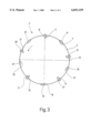
- FIG. 2 shows a basic diagram of a front view of a tool with four cutting edges
- FIG. 3 shows a basic diagram of a front view of a tool with five cutting edges.
- FIG. 1 shows a front view of a tool 1 which is preferably designed as a reamer. Grooves 5 to 13, into which cutting tips and guide bars are inserted in known manner, are formed in the circumferential surface 3 of the tool 1. A first blade insert 15--as seen in the direction of rotation of the tool leads a first guide bar 17 by an angle ⁇ . Blade 15 is situated in the groove 5.
- the lead angle ⁇ may lie in a range from 20° to 50°. In particular an angle of from 30° to 45° is selected. An angle ⁇ of approximately 40° has proven particularly advantageous and is illustrated here in FIG. 1.
- the first guide bar is inserted in the groove 7 and is fastened there in a suitable manner, for example by soldering or adhesive bonding.
- the blade insert 15 is assigned a diametrically opposite second guide bar 19 which is inserted in the groove 10.
- the first blade insert 15 and the associated guide bars 17 and 19 form a Y-shaped basic arrangement.
- the tool 1 has a second blade insert 21, which is inserted in the groove 9 and is held there in a suitable manner.
- Fastening blade inserts is known.
- crimping shoes are provided, which press the blade insert against a flank of the groove and in this way crimp it in place.
- the second blade insert 21 is inserted in the circumferential surface 3 of the tool 1 in such a way that the second guide bar 19 trails the second blade insert 21 by an angle ⁇ which may be from 20° to 50°, in particular approximately 30° to 45°.
- An angle ⁇ of approximately 40° has proven particularly advantageous and is also shown in FIG. 1.
- the tool 1 illustrated here is therefore distinguished by Y-shaped arrangement of blade insert and guide bar being provided in duplicate, the second guide bar 19 being present both in the Y-shaped arrangement of the first blade insert 15 and also in the Y-shaped arrangement of the second blade insert 21.
- a third blade insert 25 which is shown here in dashed lines and is accommodated in the groove 11, may be provided.
- This third blade insert 25 is preferably arranged diametrically opposite the first guide bar 17.
- a fourth guide bar 27, which for its part is arranged in a groove 29, may be arranged so as to trail this third blade insert 25 by approximately 40°.
- the tool 1 may therefore comprise, in addition to the first blade insert, as a further blade insert, the second blade insert 21 or the third blade insert 25 with the associated guide bars. In this way, a so-called two-edged tool is achieved. However, it is also conceivable to provide, in addition to the first blade insert 15, both the second blade insert 21 and the third blade insert 25, so as to form a three-edged tool with the associated guide bars.
- a Y-shaped basic structure In order to ensure chatter-free operation during the finish machining of drilled surfaces, a Y-shaped basic structure must always be present, provided by the arrangement of one blade insert and two guide bars, in which case--as seen in the direction of rotation of the tool indicated by an arrow--a first guide bar trails the blade insert by 40° and a second guide bar trails by 180°.
- the second guide bar is therefore arranged diametrically opposite the blade insert.
- further guide bars also forming one or two further Y-shaped arrangement structures in which single or a plurality of guide bars belong to a plurality of such arrangements.
- FIG. 2 again shows a basic diagram of a front view of a tool 1'.
- the basic structure of the tool corresponds to that which is depicted in FIG. 1, so that identical parts are provided with identical reference numerals.
- the tool depicted in FIG. 2 differs from that shown in FIG. 1 by the fact that a fourth blade insert 31, which is inserted in a suitable groove 33 arranged in the circumferential surface 3 of the tool 1', is provided.
- the tool shown here again has three Y-shaped arrangements of blade inserts and guide bars, the first blade insert 15 being assigned the guide bars 17 and 19, while the second blade insert 21 is assigned the guide bars 19 and 23 and the third blade insert 25 is assigned the guide bars 27 and 17.
- a fifth guide bar 35 which is arranged in a groove 37, may be arranged downstream of the fourth blade insert 31.
- the fifth guide bar 35 is approximately 40° downstream of the fourth blade insert 31.
- the tool 1 is guided and centered so successfully in the drilled hole to be machined that it is possible to dispense with a Y-shaped arrangement structure for the fourth blade insert 31.
- the fourth guide bar 27 is arranged practically directly opposite the fourth blade insert 31, so that here too sufficient stabilization is provided.
- FIG. 3 of a tool 1" shows an embodiment with five blade inserts or cutting edges.
- the cutting edges 1 to 4 correspond to those which are illustrated in FIG. 2. Therefore, to this extent reference is made to the description given with regard to FIG. 2.
- the guide bars 1 to 5 which are shown in FIG. 3 likewise correspond to those which have already been explained with reference to FIG. 2.
- the tool 1" illustrated here differs from the tool 1' shown in FIG. 2 only by the fact that a fifth blade insert 39, which is inserted in a suitable groove formed in the circumferential surface of the tool 1", is provided between the third guide bar 23 and the fourth guide bar 27.
- the third guide bar 23 trails the fifth blade insert 39--as seen in the direction of rotation indicated by an arrow--by approximately 40°, so that the basic arrangement which has already been mentioned with reference to the first blade insert 15 is also present for the fifth blade insert 39 and the third guide bar 23.
- the fifth guide bar 35 is arranged diametrically opposite the fifth blade insert 39, so that ultimately the Y-shaped arrangement which has already been explained with reference to the previous figures is also produced for the fifth blade insert 35.
- the tool 1" shown in FIG. 3 has a plurality of such arrangements, the first blade insert 15 and the first guide bar 17, as well as the second guide bar 19, being assigned to one another, in the same way as the second blade insert 21, the second guide bar 19 and the third guide bar 23.
- a further arrangement is provided by the third blade insert 25, the fourth guide bar 27 and the guide bar 17.
- the last Y-shaped arrangement is provided by the above-mentioned fifth blade insert 39 together with the guide bars 23 and 35.
- the tool 1" illustrated in FIG. 3 is guided optimally in the drilled surface which is to be machined.
- the tools described here with reference to FIGS. 1 to 3 are distinguished by the fact that the advance of the tool inside a drilled hole to be machined can be significantly greater than with conventional tools. Tests have shown that the advance with a tool which has three cutting edges or blade inserts, as explained in FIG. 1, can be greater by a factor of 3 than with conventional tools. Correspondingly greater advance values result from the tools with 4 and 5 cutting edges.
- the tool described here is particularly suitable for the material-removing finishing and precision machining of drilled surfaces in workpieces made of metal.
- the number of cutting edges and guide bars which is selected depends, inter alia, on the diameter of the tool, since, as is known, it is necessary to assign to each cutting edge a leading--as seen in the direction of rotation--chip space, in order to ensure that the chips are removed successfully and hence to ensure fault-free operation of the tool.
- the invention can be employed to particular advantage on reamers.
- tools used for the material-removing finishing machining of drilled surfaces in workpieces made of metal may also be designed in accordance with the teaching of the invention.
Landscapes
- Engineering & Computer Science (AREA)
- Mechanical Engineering (AREA)
- Milling, Broaching, Filing, Reaming, And Others (AREA)
- Drilling Tools (AREA)
- Finish Polishing, Edge Sharpening, And Grinding By Specific Grinding Devices (AREA)
- Cutting Tools, Boring Holders, And Turrets (AREA)
- Grinding Of Cylindrical And Plane Surfaces (AREA)
- Mechanical Treatment Of Semiconductor (AREA)
Applications Claiming Priority (3)
| Application Number | Priority Date | Filing Date | Title |
|---|---|---|---|
| DE19621295 | 1996-05-25 | ||
| DE19621295A DE19621295C2 (de) | 1996-05-25 | 1996-05-25 | Reibahle für die spanabhebende Feinbearbeitung |
| PCT/EP1997/002669 WO1997045223A1 (de) | 1996-05-25 | 1997-05-24 | Werkzeug für die spanabhebende feinbearbeitung |
Publications (1)
| Publication Number | Publication Date |
|---|---|
| US6033159A true US6033159A (en) | 2000-03-07 |
Family
ID=7795437
Family Applications (1)
| Application Number | Title | Priority Date | Filing Date |
|---|---|---|---|
| US09/142,151 Expired - Lifetime US6033159A (en) | 1996-05-25 | 1997-05-24 | Material-removing precision machining tool |
Country Status (10)
| Country | Link |
|---|---|
| US (1) | US6033159A (de) |
| EP (1) | EP0907449B1 (de) |
| JP (1) | JP3288718B2 (de) |
| AT (1) | ATE232767T1 (de) |
| DE (2) | DE19621295C2 (de) |
| DK (1) | DK0907449T3 (de) |
| ES (1) | ES2191181T3 (de) |
| PT (1) | PT907449E (de) |
| RU (1) | RU2154557C2 (de) |
| WO (1) | WO1997045223A1 (de) |
Cited By (19)
| Publication number | Priority date | Publication date | Assignee | Title |
|---|---|---|---|---|
| US6254319B1 (en) * | 1997-03-03 | 2001-07-03 | Andreas Maier | Friction and vertical cutting tool |
| WO2003035316A1 (de) * | 2001-09-11 | 2003-05-01 | Komet Präzisionswerkzeuge Robert Breuning Gmbh | Kombinationswerkzeug |
| US20030103821A1 (en) * | 2001-12-04 | 2003-06-05 | Mapal Fabrik Fur Prazisionswerkzeuge Dr. Kress Kg | Tool for the precision machining of surfaces |
| US20030203711A1 (en) * | 2002-03-07 | 2003-10-30 | Jorg Agarico | Guide gib for gib-guided cutting tools |
| US6668827B2 (en) * | 2000-05-16 | 2003-12-30 | Nektar Therapeutics | Systems devices and methods for opening receptacles having a powder to be fluidized |
| US6761514B2 (en) * | 2001-10-19 | 2004-07-13 | Master Tool Corporation | Hollow mill tool |
| US20070237593A1 (en) * | 2005-07-25 | 2007-10-11 | Takuji Nomura | Machine reamer |
| US20120321402A1 (en) * | 2008-11-12 | 2012-12-20 | Guehring Ohg | Multi-blade cutting and drilling finishing tool |
| CN103008789A (zh) * | 2012-11-27 | 2013-04-03 | 大连经济技术开发区伊达工具有限公司 | 一种深孔加工用铰刀 |
| US20140169896A1 (en) * | 2012-12-14 | 2014-06-19 | Kennametal Inc. | Metal-Cutting Tool, In Particular Reaming Tool |
| DE102013202576A1 (de) | 2013-02-18 | 2014-08-21 | Kennametal Inc. | Zerspanungswerkzeug, insbesondere Reibwerkzeug sowie Verfahren zu seiner Herstellung |
| US20150151373A1 (en) * | 2012-06-05 | 2015-06-04 | Snecma | Calibration head for the drilling of shafts |
| US20160193671A1 (en) * | 2013-07-24 | 2016-07-07 | Toyota Jidosha Kabushiki Kaisha | Cutting tool |
| EP2560778B1 (de) | 2010-04-23 | 2017-09-06 | TBT Tiefbohrtechnik GmbH + Co | Bohrkopf für ein tiefbohrwerkzeug zum bta-tiefbohren und tiefbohrwerkzeug |
| US9884382B2 (en) | 2012-11-05 | 2018-02-06 | Kennametal Inc. | Rotary tool for precision machining of a drilled hole in a workpiece, and method for precision machining of a drilled hole |
| US10654110B2 (en) | 2017-03-22 | 2020-05-19 | Kennametal Inc. | Cutting tool, in particular a boring bar, and method for machining a number of holes |
| US11065623B1 (en) * | 2017-05-31 | 2021-07-20 | Stephen Rock | Grinding blade for an angle grinder |
| US11407047B2 (en) * | 2018-06-28 | 2022-08-09 | A.L.M.T. Corp. | Reamer |
| US11590583B2 (en) | 2017-09-22 | 2023-02-28 | Kennametal Inc. | Machining tool, processing device and method for processing workpieces |
Families Citing this family (6)
| Publication number | Priority date | Publication date | Assignee | Title |
|---|---|---|---|---|
| DE19855471C2 (de) * | 1998-12-01 | 2003-08-21 | Guehring Ohg | Werkzeug zur spanabtragenden Feinbearbeitung von Bohrungsoberflächen mit wenigstens einer austauschbaren Schneidplatte |
| DE102005034422B4 (de) * | 2005-07-13 | 2008-10-23 | MAPAL Fabrik für Präzisionswerkzeuge Dr. Kress KG | Reibahle und Verfahren zu deren Herstellung |
| DE102006024569A1 (de) * | 2006-05-23 | 2007-12-06 | Belin Yvon S.A. | Werkzeug zur spanabhebenden Feinbearbeitung von Werkstücken |
| JP2014079814A (ja) * | 2012-10-12 | 2014-05-08 | Mitsubishi Materials Corp | 穴加工工具 |
| DE102014208102B4 (de) * | 2014-04-29 | 2016-07-21 | MAPAL Fabrik für Präzisionswerkzeuge Dr. Kress KG | Zerspanungswerkzeug |
| CN108000052A (zh) * | 2017-11-03 | 2018-05-08 | 中国航发北京航科发动机控制系统科技有限责任公司 | 一种锥形五棱挤光刀 |
Citations (10)
| Publication number | Priority date | Publication date | Assignee | Title |
|---|---|---|---|---|
| GB658510A (en) * | 1949-12-30 | 1951-10-10 | Dario Livio | A reamer |
| DE2549260A1 (de) * | 1975-11-04 | 1977-05-12 | Mapal Fab Praezision | Mehrschneiden-reibahle |
| DE2556977A1 (de) * | 1975-12-18 | 1977-06-30 | Botek Praezisions Bohrtechnik | Tiefbohrwerkzeug zum aufbohren |
| DE7726025U1 (de) * | 1977-08-23 | 1977-11-24 | Wilhelm Hegenscheidt, Gmbh, 5140 Erkelenz | Pendelmesserkopf |
| US4184794A (en) * | 1977-04-09 | 1980-01-22 | Ferdinand Henninghaus | Device for machining the internal wall of a cylinder |
| DE2910828A1 (de) * | 1979-03-20 | 1980-09-25 | Wezel & Co Biax Werkzeuge | Reibahle mit schneidplatten aus hartmetall |
| US4264246A (en) * | 1978-06-30 | 1981-04-28 | W. Hegenscheidt Gesellschaft Mbh | Boring tool for boring holes of substantial length |
| DE3429498A1 (de) * | 1984-08-10 | 1986-02-13 | Mapal Fabrik für Präzisionswerkzeuge Dr.Kress KG, 7080 Aalen | Einschneidenreibahle |
| US5125772A (en) * | 1988-03-05 | 1992-06-30 | Mapal Fabrik Fur Prazisionswerkzeuge Dr. Kress Kg | Single cut reamer with chip guiding device |
| DE4329553A1 (de) * | 1993-09-02 | 1995-03-09 | Beck August Gmbh Co | Einmesser-Reibahle |
Family Cites Families (6)
| Publication number | Priority date | Publication date | Assignee | Title |
|---|---|---|---|---|
| SU464412A1 (ru) * | 1973-03-27 | 1975-03-25 | Предприятие П/Я М-5357 | Развертка |
| SU852458A1 (ru) * | 1979-02-12 | 1981-08-07 | Всесоюзный Научно-Исследовательскийи Проектно-Технологический Институтнефтяного Машиностроения | Режущий инструмент дл обработкиОТВЕРСТий |
| SU859063A1 (ru) * | 1979-05-10 | 1981-08-30 | Куйбышевский Политехнический Институт, Филиал В Г.Сызрани | Развертка |
| SU1484489A1 (ru) * | 1987-07-09 | 1989-06-07 | Всесоюзный Научно-Исследовательский Инструментальный Институт | Развертка одностороннего резани |
| RO105779B1 (ro) * | 1990-02-15 | 1992-12-30 | Institutul Politehnic | Alezor |
| DE4202751A1 (de) * | 1992-01-31 | 1993-08-05 | Mapal Fab Praezision | Einmesser-reibahle |
-
1996
- 1996-05-25 DE DE19621295A patent/DE19621295C2/de not_active Expired - Fee Related
-
1997
- 1997-05-24 US US09/142,151 patent/US6033159A/en not_active Expired - Lifetime
- 1997-05-24 DE DE59709354T patent/DE59709354D1/de not_active Expired - Lifetime
- 1997-05-24 DK DK97927033T patent/DK0907449T3/da active
- 1997-05-24 WO PCT/EP1997/002669 patent/WO1997045223A1/de not_active Ceased
- 1997-05-24 PT PT97927033T patent/PT907449E/pt unknown
- 1997-05-24 JP JP54157997A patent/JP3288718B2/ja not_active Expired - Fee Related
- 1997-05-24 ES ES97927033T patent/ES2191181T3/es not_active Expired - Lifetime
- 1997-05-24 RU RU98110574/02A patent/RU2154557C2/ru not_active IP Right Cessation
- 1997-05-24 AT AT97927033T patent/ATE232767T1/de active
- 1997-05-24 EP EP97927033A patent/EP0907449B1/de not_active Expired - Lifetime
Patent Citations (12)
| Publication number | Priority date | Publication date | Assignee | Title |
|---|---|---|---|---|
| GB658510A (en) * | 1949-12-30 | 1951-10-10 | Dario Livio | A reamer |
| DE2549260A1 (de) * | 1975-11-04 | 1977-05-12 | Mapal Fab Praezision | Mehrschneiden-reibahle |
| US4076445A (en) * | 1975-11-04 | 1978-02-28 | Mapal Fabrik Fur Prazisionswerkzeuge Dr. Kress Kg | Multiple blade reamer |
| DE2556977A1 (de) * | 1975-12-18 | 1977-06-30 | Botek Praezisions Bohrtechnik | Tiefbohrwerkzeug zum aufbohren |
| US4133399A (en) * | 1975-12-18 | 1979-01-09 | Wilhelm Hegenscheidt Gmbh | Boring device |
| US4184794A (en) * | 1977-04-09 | 1980-01-22 | Ferdinand Henninghaus | Device for machining the internal wall of a cylinder |
| DE7726025U1 (de) * | 1977-08-23 | 1977-11-24 | Wilhelm Hegenscheidt, Gmbh, 5140 Erkelenz | Pendelmesserkopf |
| US4264246A (en) * | 1978-06-30 | 1981-04-28 | W. Hegenscheidt Gesellschaft Mbh | Boring tool for boring holes of substantial length |
| DE2910828A1 (de) * | 1979-03-20 | 1980-09-25 | Wezel & Co Biax Werkzeuge | Reibahle mit schneidplatten aus hartmetall |
| DE3429498A1 (de) * | 1984-08-10 | 1986-02-13 | Mapal Fabrik für Präzisionswerkzeuge Dr.Kress KG, 7080 Aalen | Einschneidenreibahle |
| US5125772A (en) * | 1988-03-05 | 1992-06-30 | Mapal Fabrik Fur Prazisionswerkzeuge Dr. Kress Kg | Single cut reamer with chip guiding device |
| DE4329553A1 (de) * | 1993-09-02 | 1995-03-09 | Beck August Gmbh Co | Einmesser-Reibahle |
Cited By (31)
| Publication number | Priority date | Publication date | Assignee | Title |
|---|---|---|---|---|
| US6254319B1 (en) * | 1997-03-03 | 2001-07-03 | Andreas Maier | Friction and vertical cutting tool |
| US7814905B2 (en) | 2000-05-16 | 2010-10-19 | Novartis Ag | Systems devices and methods for opening receptacles having a powder to be fluidized |
| US6668827B2 (en) * | 2000-05-16 | 2003-12-30 | Nektar Therapeutics | Systems devices and methods for opening receptacles having a powder to be fluidized |
| US20050161041A1 (en) * | 2000-05-16 | 2005-07-28 | Carlos Schuler | Systems devices and methods for opening receptacles having a powder to be fluidized |
| WO2003035316A1 (de) * | 2001-09-11 | 2003-05-01 | Komet Präzisionswerkzeuge Robert Breuning Gmbh | Kombinationswerkzeug |
| US20040194592A1 (en) * | 2001-09-11 | 2004-10-07 | Erich Feil | Combination tool |
| US7089837B2 (en) | 2001-09-11 | 2006-08-15 | Komet Praezisionswerkzeuge Robert Breuning Gmbh | Combination tool |
| US6761514B2 (en) * | 2001-10-19 | 2004-07-13 | Master Tool Corporation | Hollow mill tool |
| US20030103821A1 (en) * | 2001-12-04 | 2003-06-05 | Mapal Fabrik Fur Prazisionswerkzeuge Dr. Kress Kg | Tool for the precision machining of surfaces |
| US6913428B2 (en) * | 2001-12-04 | 2005-07-05 | Mapal Fabrik Fur Prazisionswerkzeuge Dr. Kress Kg | Tool for the precision machining of surfaces |
| US20030203711A1 (en) * | 2002-03-07 | 2003-10-30 | Jorg Agarico | Guide gib for gib-guided cutting tools |
| US20070237593A1 (en) * | 2005-07-25 | 2007-10-11 | Takuji Nomura | Machine reamer |
| US7658575B2 (en) * | 2005-07-25 | 2010-02-09 | Unitac, Inc. | Machine reamer |
| US20120321402A1 (en) * | 2008-11-12 | 2012-12-20 | Guehring Ohg | Multi-blade cutting and drilling finishing tool |
| US9056360B2 (en) * | 2008-11-12 | 2015-06-16 | Guehring Ohg | Multi-blade cutting and drilling finishing tool |
| EP2560778B1 (de) | 2010-04-23 | 2017-09-06 | TBT Tiefbohrtechnik GmbH + Co | Bohrkopf für ein tiefbohrwerkzeug zum bta-tiefbohren und tiefbohrwerkzeug |
| US9815130B2 (en) * | 2012-06-05 | 2017-11-14 | Snecma | Calibration head for the drilling of shafts |
| US20150151373A1 (en) * | 2012-06-05 | 2015-06-04 | Snecma | Calibration head for the drilling of shafts |
| US10807176B2 (en) | 2012-11-05 | 2020-10-20 | Kennametal Inc. | Rotary tool for precision machining of a drilled hole in a workpiece, and method for precision machining of a drilled hole |
| US9884382B2 (en) | 2012-11-05 | 2018-02-06 | Kennametal Inc. | Rotary tool for precision machining of a drilled hole in a workpiece, and method for precision machining of a drilled hole |
| CN103008789A (zh) * | 2012-11-27 | 2013-04-03 | 大连经济技术开发区伊达工具有限公司 | 一种深孔加工用铰刀 |
| US9352405B2 (en) * | 2012-12-14 | 2016-05-31 | Kennametal Inc. | Metal-cutting tool, in particular reaming tool |
| US20140169896A1 (en) * | 2012-12-14 | 2014-06-19 | Kennametal Inc. | Metal-Cutting Tool, In Particular Reaming Tool |
| DE102013202576B4 (de) * | 2013-02-18 | 2015-05-13 | Kennametal Inc. | Zerspanungswerkzeug, insbesondere Reibwerkzeug sowie Verfahren zu seiner Herstellung |
| WO2014127105A3 (en) * | 2013-02-18 | 2014-12-31 | Kennametal Inc. | Metal-cutting tool, in particular reaming tool, and method for manufacturing this same |
| DE102013202576A1 (de) | 2013-02-18 | 2014-08-21 | Kennametal Inc. | Zerspanungswerkzeug, insbesondere Reibwerkzeug sowie Verfahren zu seiner Herstellung |
| US20160193671A1 (en) * | 2013-07-24 | 2016-07-07 | Toyota Jidosha Kabushiki Kaisha | Cutting tool |
| US10654110B2 (en) | 2017-03-22 | 2020-05-19 | Kennametal Inc. | Cutting tool, in particular a boring bar, and method for machining a number of holes |
| US11065623B1 (en) * | 2017-05-31 | 2021-07-20 | Stephen Rock | Grinding blade for an angle grinder |
| US11590583B2 (en) | 2017-09-22 | 2023-02-28 | Kennametal Inc. | Machining tool, processing device and method for processing workpieces |
| US11407047B2 (en) * | 2018-06-28 | 2022-08-09 | A.L.M.T. Corp. | Reamer |
Also Published As
| Publication number | Publication date |
|---|---|
| JPH11507303A (ja) | 1999-06-29 |
| DE19621295A1 (de) | 1997-11-27 |
| WO1997045223A1 (de) | 1997-12-04 |
| JP3288718B2 (ja) | 2002-06-04 |
| EP0907449A1 (de) | 1999-04-14 |
| DE59709354D1 (de) | 2003-03-27 |
| DE19621295C2 (de) | 1998-08-27 |
| DK0907449T3 (da) | 2003-06-10 |
| ATE232767T1 (de) | 2003-03-15 |
| RU2154557C2 (ru) | 2000-08-20 |
| EP0907449B1 (de) | 2003-02-19 |
| PT907449E (pt) | 2003-07-31 |
| ES2191181T3 (es) | 2003-09-01 |
Similar Documents
| Publication | Publication Date | Title |
|---|---|---|
| US6033159A (en) | Material-removing precision machining tool | |
| EP0953396B1 (de) | Gewindebohrer | |
| US5855458A (en) | Rotary cutter | |
| JP2856404B2 (ja) | 切削インサート | |
| US4274771A (en) | Boring reamer with end mill cutters | |
| EP2098319B1 (de) | Verfahren zur anordnung von schneideinsätzen in einem bohrer | |
| US8708618B2 (en) | Reamer | |
| US7351017B2 (en) | Solid drill bit for machine tools | |
| JPS6111729B2 (de) | ||
| JP2012096356A (ja) | 軌道エンドミル | |
| GB2078144A (en) | Annular hole cutter | |
| US6200073B1 (en) | Combination chamfering and milling tool | |
| US5211635A (en) | Drill with trimming attachment | |
| CN102105251B (zh) | 具有支承元件的旋转式刀具 | |
| GB2024056A (en) | Preturning or shaft turning tool | |
| JP2008264979A (ja) | 穿孔用回転切削工具 | |
| KR970006957B1 (ko) | 고속 버니싱드릴(High speed burnishing drill) | |
| EP1561535B1 (de) | Schneidwerkzeug und Verfahren zu dessen Benutzung | |
| US2891429A (en) | Bearing pocket boring tool | |
| CN1747805B (zh) | 用于不同类型去屑加工的刀具 | |
| US6135680A (en) | Boring tool with staggered rotary cutting inserts | |
| US5201616A (en) | Hole finishing tool with improved axial alignment | |
| JPH0258042B2 (de) | ||
| JPH09192930A (ja) | ねじ切りフライス | |
| JP2002521223A (ja) | 浅穴用ドリルビット |
Legal Events
| Date | Code | Title | Description |
|---|---|---|---|
| AS | Assignment |
Owner name: MAPAL FABRIK FUR PRAZISIONSWERKZEUGE DR. KRESS KG, Free format text: ASSIGNMENT OF ASSIGNORS INTEREST;ASSIGNORS:KRESS, DIETER;HABERLE, FRIEDRICH;REEL/FRAME:009630/0723 Effective date: 19980720 |
|
| STCF | Information on status: patent grant |
Free format text: PATENTED CASE |
|
| FPAY | Fee payment |
Year of fee payment: 4 |
|
| FPAY | Fee payment |
Year of fee payment: 8 |
|
| FPAY | Fee payment |
Year of fee payment: 12 |