US6033190A - Flat faced bearing housing engaging flat faced pump rotor housing - Google Patents
Flat faced bearing housing engaging flat faced pump rotor housing Download PDFInfo
- Publication number
- US6033190A US6033190A US09/000,796 US79697A US6033190A US 6033190 A US6033190 A US 6033190A US 79697 A US79697 A US 79697A US 6033190 A US6033190 A US 6033190A
- Authority
- US
- United States
- Prior art keywords
- housing
- bearing housing
- pressure
- housing cap
- cap
- Prior art date
- Legal status (The legal status is an assumption and is not a legal conclusion. Google has not performed a legal analysis and makes no representation as to the accuracy of the status listed.)
- Expired - Lifetime
Links
- 230000001105 regulatory effect Effects 0.000 claims abstract description 15
- 239000012530 fluid Substances 0.000 claims abstract description 13
- 238000005086 pumping Methods 0.000 claims abstract description 3
- 238000009415 formwork Methods 0.000 claims 1
- 238000004519 manufacturing process Methods 0.000 description 4
- 238000007789 sealing Methods 0.000 description 3
- 238000004512 die casting Methods 0.000 description 1
- 238000009434 installation Methods 0.000 description 1
- 238000000034 method Methods 0.000 description 1
- 238000003825 pressing Methods 0.000 description 1
- 230000000717 retained effect Effects 0.000 description 1
Images
Classifications
-
- F—MECHANICAL ENGINEERING; LIGHTING; HEATING; WEAPONS; BLASTING
- F04—POSITIVE - DISPLACEMENT MACHINES FOR LIQUIDS; PUMPS FOR LIQUIDS OR ELASTIC FLUIDS
- F04C—ROTARY-PISTON, OR OSCILLATING-PISTON, POSITIVE-DISPLACEMENT MACHINES FOR LIQUIDS; ROTARY-PISTON, OR OSCILLATING-PISTON, POSITIVE-DISPLACEMENT PUMPS
- F04C14/00—Control of, monitoring of, or safety arrangements for, machines, pumps or pumping installations
- F04C14/24—Control of, monitoring of, or safety arrangements for, machines, pumps or pumping installations characterised by using valves controlling pressure or flow rate, e.g. discharge valves or unloading valves
- F04C14/26—Control of, monitoring of, or safety arrangements for, machines, pumps or pumping installations characterised by using valves controlling pressure or flow rate, e.g. discharge valves or unloading valves using bypass channels
-
- F—MECHANICAL ENGINEERING; LIGHTING; HEATING; WEAPONS; BLASTING
- F04—POSITIVE - DISPLACEMENT MACHINES FOR LIQUIDS; PUMPS FOR LIQUIDS OR ELASTIC FLUIDS
- F04C—ROTARY-PISTON, OR OSCILLATING-PISTON, POSITIVE-DISPLACEMENT MACHINES FOR LIQUIDS; ROTARY-PISTON, OR OSCILLATING-PISTON, POSITIVE-DISPLACEMENT PUMPS
- F04C2/00—Rotary-piston machines or pumps
- F04C2/30—Rotary-piston machines or pumps having the characteristics covered by two or more groups F04C2/02, F04C2/08, F04C2/22, F04C2/24 or having the characteristics covered by one of these groups together with some other type of movement between co-operating members
- F04C2/34—Rotary-piston machines or pumps having the characteristics covered by two or more groups F04C2/02, F04C2/08, F04C2/22, F04C2/24 or having the characteristics covered by one of these groups together with some other type of movement between co-operating members having the movement defined in groups F04C2/08 or F04C2/22 and relative reciprocation between the co-operating members
- F04C2/344—Rotary-piston machines or pumps having the characteristics covered by two or more groups F04C2/02, F04C2/08, F04C2/22, F04C2/24 or having the characteristics covered by one of these groups together with some other type of movement between co-operating members having the movement defined in groups F04C2/08 or F04C2/22 and relative reciprocation between the co-operating members with vanes reciprocating with respect to the inner member
- F04C2/3446—Rotary-piston machines or pumps having the characteristics covered by two or more groups F04C2/02, F04C2/08, F04C2/22, F04C2/24 or having the characteristics covered by one of these groups together with some other type of movement between co-operating members having the movement defined in groups F04C2/08 or F04C2/22 and relative reciprocation between the co-operating members with vanes reciprocating with respect to the inner member the inner and outer member being in contact along more than one line or surface
Definitions
- the invention relates to a vane cell pump for pumping a pressure fluid from a container to a consumer.
- a set of rotors of the vane cell pump includes a cam ring into which a rotor is rotatably inserted.
- the rotor has radially oriented slots in which vanes are displaceably inserted.
- work chambers are formed, which are defined in the axial direction by control faces of adjacent control plates.
- the rotor set is inserted into a pressure-fluid-filled interior of a housing, which comprises a bearing housing and a housing cap. In the bearing housing, the rotor is supported by means of a drive shaft that is braced in an axial direction on the housing cap.
- a suction connection for connection of the container and a pressure connection for connecting the consumer are provided in the bearing housing.
- a flow regulating valve for regulating the pressure fluid pumped to the pressure connection is disposed in the bearing housing.
- a pressure limiting valve is also disposed in the bearing housing.
- Suction and pressure conduits that connect the work chambers with the suction connection, the flow regulating valve and the pressure limiting valve, are also disposed in the bearing housing.
- a vane cell pump of this kind is known for instance from U.S. Pat. No. 5,098,259.
- This pump has a very compact design.
- a cylindrical tight fit between the housing cap and the bearing housing results in a widening of the housing cap in this region.
- the tight fit must be executed with great precision, since the drive shaft has not only its bearing point in the bearing housing but also a second bearing in a control plate, which in turn is centered in the housing cap.
- the production of the various close-fit points entails considerable production expense. Additional cost is entailed in the assembly of the bearing housing and housing cap, because a seal between the two parts must be mounted very carefully so that it will not be sheared off when the housing cap is slipped over the bearing housing.
- the object of the invention is to improve the known pump in such a way that production and installation costs can be reduced.
- the vane cell pump of the invention in that the drive shaft is supported in the radial direction solely in the bearing housing and no longer in the control plate.
- the tight fit of the control plate in the housing cap can be dispensed with.
- Both the bearing housing and the housing cap have flat connection faces. A cylindrical tight fit is avoided.
- the housing cap is centered relative to the bearing housing solely by means of screws, with which it is secured to the bearing housing.
- the cam ring is likewise centered solely relative to the bearing housing.
- the seal between the housing cap and the bearing housing can be accomplished by a simple flat seal.
- it is expediently embodied as an C ring in an annular groove in one of the two flat faces, that is, in either the housing cap or the bearing housing.
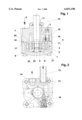
- FIG. 1 a longitudinal section through the vane cell pump of the invention.
- FIG. 2 a plan view on the vane cell pump in the direction of the arrow II in FIG. 1, cut away in portions.
- the vane cell pump is used to pump a pressure fluid from a container, not shown, to a consumer, not shown but embodied for instance by a power steering system.
- a rotor set 3 is inserted into a pressure-fluid-filled interior 1 of a housing 2.
- the rotor set 3 comprises a cam ring 4 and a rotor 5.
- the rotor 5 is disposed in the interior of the cam ring 4 and has radially oriented slots in which vanes 6 are displaceably inserted.
- Work chambers are formed between the cam ring 4, the rotor 5, and the vanes 6; they are defined in the axial direction by control faces of adjacent control plates 7 and 8.
- the housing 2 is composed of a bearing housing 10 and a cup-shaped housing cap 11.
- the rotor 5 is supported in the bearing housing 10 via a drive shaft 12.
- the bearing point in the bearing housing 10 is the sole bearing of the drive shaft 12. This means that the drive shaft 12 is not supported in the radial direction in the housing cap 11. Instead, the drive shaft 12 is supported only axially on the housing cap 11.
- a seal 19 may be provided around drive shaft 12.
- both a suction connection 13 for connection to the container and a pressure connection 14 for connecting the consumer are disposed in the bearing housing 10.
- a flow regulating valve 15 for regulating the pressure fluid pumped to the pressure connection 14.
- a pressure limiting valve 16 is likewise included in the bearing housing 10.
- the embodiment of the flow regulating valve 15 and of the pressure limiting valve 16 is well known, for instance from U.S. Pat. No. 5,098,259, and will therefore not be described further here.
- Suction and pressure conduits, which connect the work chambers to the suction connection 13, to the flow regulating valve 15, and to the pressure limiting valve 16, are also disposed in the bearing housing 10. These conduits are likewise well known and will therefore not be described further here other than to note that the ellipse 9 on the flow regulating valve 15 of FIG. 1 is a port opening up to a back-up chamber of the valve 15.
- the pressure limiting valve 16 may be integrated in the flow regulating valve 15. In the preferred exemplary embodiment, however the two valves are disposed separately from one another.
- the bearing housing 10 has a flat face 17 on its side toward the housing cap 11.
- the housing cap 11 likewise has a flat face 18 on its side toward the bearing housing 10.
- a seal preferably in the form of an 0 ring 20, which is placed in an axially open annular groove in the bearing housing 10 or in the housing cap 11.
- the two housing parts, the bearing housing 10 and the housing cap 11 have very simple shapes and can therefore be precast or cast in finished form essentially in the pressure diecasting process.
- the housing cap 11 is secured to the bearing housing 10 by screws 21 and is centered relative to the bearing housing 10 only by the screws 21. Further centering of the two parts to one another is unnecessary, since no other parts are adjusted or centered in the housing cap 11.
- the drive shaft 12 is supported in the radial direction only in the bearing housing 10 and is braced only in the axial direction on the housing cap 11. In the tension direction, the drive shaft 12 is axially retained via a securing ring 22, the rotor 5, and the control plate 7.
- sealing ring 23 which on the one hand divides the interior 1, acted upon by high pressure, from the drive shaft 12 and on the other, as an elastic element, assures gap compensation between the housing cap 11 and the control plate 8.
- the sealing ring 23 has the task, when the pump is stopped, of pressing the control plate 8, the cam ring 4 and the control plate 7 against the surface 18, in order to compensate for production tolerances.
- the screws 21 are located outside the interior 1, so that no additional sealing is required in that area.
- cam ring 4 and the control plates 7 and 8 are centered relative to the bearing housing 10 by means of two pins, known per se and therefore not described further here. No further centering is necessary.
- the design of the vane cell pump according to the invention makes a very simple assembly possible: The various parts need merely be stacked on the other and then screwed together. The O-ring 20 cannot be sheared off during assembly.
Landscapes
- Engineering & Computer Science (AREA)
- Mechanical Engineering (AREA)
- General Engineering & Computer Science (AREA)
- Physics & Mathematics (AREA)
- Fluid Mechanics (AREA)
- Rotary Pumps (AREA)
- Details And Applications Of Rotary Liquid Pumps (AREA)
- Details Of Reciprocating Pumps (AREA)
Applications Claiming Priority (2)
| Application Number | Priority Date | Filing Date | Title |
|---|---|---|---|
| DE4416077 | 1994-05-06 | ||
| DE4416077A DE4416077A1 (de) | 1994-05-06 | 1994-05-06 | Flügelzellenpumpe |
Related Parent Applications (1)
| Application Number | Title | Priority Date | Filing Date |
|---|---|---|---|
| US08732463 Continuation | 1996-11-05 |
Publications (1)
| Publication Number | Publication Date |
|---|---|
| US6033190A true US6033190A (en) | 2000-03-07 |
Family
ID=6517511
Family Applications (1)
| Application Number | Title | Priority Date | Filing Date |
|---|---|---|---|
| US09/000,796 Expired - Lifetime US6033190A (en) | 1994-05-06 | 1997-12-30 | Flat faced bearing housing engaging flat faced pump rotor housing |
Country Status (7)
| Country | Link |
|---|---|
| US (1) | US6033190A (ja) |
| EP (1) | EP0760907B1 (ja) |
| JP (1) | JP3859702B2 (ja) |
| BR (1) | BR9507706A (ja) |
| DE (2) | DE4416077A1 (ja) |
| ES (1) | ES2109823T3 (ja) |
| WO (1) | WO1995030834A1 (ja) |
Cited By (2)
| Publication number | Priority date | Publication date | Assignee | Title |
|---|---|---|---|---|
| US6179581B1 (en) * | 1997-12-23 | 2001-01-30 | Luk Fahrzeug-Hydraulik Gmbh & Co. Kg | Pump connection to drive shaft |
| US20090285709A1 (en) * | 2008-05-19 | 2009-11-19 | Mooy Robert H | Vane pump |
Families Citing this family (12)
| Publication number | Priority date | Publication date | Assignee | Title |
|---|---|---|---|---|
| NL8601312A (nl) | 1986-05-22 | 1987-12-16 | Bob Hoogenboom | Zuigermotor met evenwijdige rond de drijfas geplaatste cylinders. |
| DE19635801B4 (de) * | 1996-09-04 | 2005-04-28 | Zahnradfabrik Friedrichshafen | Hochdruckpumpe mit Arbeitsschiebern |
| DE19927400A1 (de) * | 1998-06-24 | 1999-12-30 | Luk Fahrzeug Hydraulik | Hydraulische Fördereinrichtung |
| DE19832719B4 (de) * | 1998-07-21 | 2006-10-26 | Zf Friedrichshafen Ag | Flügelzellenpumpe |
| DE19833374B4 (de) * | 1998-07-24 | 2007-03-22 | Zf Friedrichshafen Ag | Verdrängerpumpe |
| DE102005059475A1 (de) * | 2005-12-13 | 2007-06-14 | Zf Lenksysteme Gmbh | Einrichtung zur Druckmittelversorgung |
| DE102006052996A1 (de) * | 2006-11-10 | 2008-05-15 | Zf Lenksysteme Gmbh | Flügelzellenpumpe |
| DE102015208643A1 (de) | 2014-05-20 | 2015-11-26 | Schaeffler Technologies AG & Co. KG | Flügelzellenmaschine |
| DE102015105933B4 (de) | 2015-04-17 | 2018-04-26 | Schwäbische Hüttenwerke Automotive GmbH | Pumpe |
| DE102016209396A1 (de) | 2016-05-31 | 2017-11-30 | Schaeffler Technologies AG & Co. KG | Pumpe mit Wälzlagerung |
| DE102023111244A1 (de) * | 2023-05-02 | 2024-11-07 | Itt Bornemann Gmbh | Doppelflutige Pumpe |
| DE102023111408A1 (de) | 2023-05-03 | 2024-11-07 | Itt Bornemann Gmbh | Einflutige Schraubenspindelpumpe |
Citations (6)
| Publication number | Priority date | Publication date | Assignee | Title |
|---|---|---|---|---|
| US4289454A (en) * | 1978-10-03 | 1981-09-15 | Jidosha Kiki Co., Ltd. | Rotary hydraulic device |
| US4473341A (en) * | 1981-10-08 | 1984-09-25 | Jidosha Kiki Co., Ltd. | Balanced vane oil pumps |
| US4505649A (en) * | 1981-09-25 | 1985-03-19 | Jidosha Kiki Co., Ltd. | Vane pumps |
| US4637782A (en) * | 1984-02-04 | 1987-01-20 | Vickers Systems Gmbh | Rotary vane pump |
| US4715793A (en) * | 1984-04-11 | 1987-12-29 | Zahnradfabrik Friedrichshafen, Ag. | Flow regulating rotary vane pump |
| US5236315A (en) * | 1990-06-11 | 1993-08-17 | Atsugi Unisia Corporation | Hydraulic pump for power-assisted steering system |
Family Cites Families (2)
| Publication number | Priority date | Publication date | Assignee | Title |
|---|---|---|---|---|
| DE3579829D1 (en) * | 1984-02-01 | 1990-10-31 | Toyoda Machine Works Ltd | Fluegelpumpe. |
| JP2840087B2 (ja) * | 1989-08-29 | 1998-12-24 | 株式会社ユニシアジェックス | 液体ポンプ |
-
1994
- 1994-05-06 DE DE4416077A patent/DE4416077A1/de not_active Withdrawn
-
1995
- 1995-04-29 JP JP52865695A patent/JP3859702B2/ja not_active Expired - Fee Related
- 1995-04-29 ES ES95919993T patent/ES2109823T3/es not_active Expired - Lifetime
- 1995-04-29 WO PCT/EP1995/001645 patent/WO1995030834A1/de not_active Ceased
- 1995-04-29 BR BR9507706A patent/BR9507706A/pt not_active IP Right Cessation
- 1995-04-29 DE DE59500922T patent/DE59500922D1/de not_active Expired - Lifetime
- 1995-04-29 EP EP95919993A patent/EP0760907B1/de not_active Expired - Lifetime
-
1997
- 1997-12-30 US US09/000,796 patent/US6033190A/en not_active Expired - Lifetime
Patent Citations (6)
| Publication number | Priority date | Publication date | Assignee | Title |
|---|---|---|---|---|
| US4289454A (en) * | 1978-10-03 | 1981-09-15 | Jidosha Kiki Co., Ltd. | Rotary hydraulic device |
| US4505649A (en) * | 1981-09-25 | 1985-03-19 | Jidosha Kiki Co., Ltd. | Vane pumps |
| US4473341A (en) * | 1981-10-08 | 1984-09-25 | Jidosha Kiki Co., Ltd. | Balanced vane oil pumps |
| US4637782A (en) * | 1984-02-04 | 1987-01-20 | Vickers Systems Gmbh | Rotary vane pump |
| US4715793A (en) * | 1984-04-11 | 1987-12-29 | Zahnradfabrik Friedrichshafen, Ag. | Flow regulating rotary vane pump |
| US5236315A (en) * | 1990-06-11 | 1993-08-17 | Atsugi Unisia Corporation | Hydraulic pump for power-assisted steering system |
Cited By (3)
| Publication number | Priority date | Publication date | Assignee | Title |
|---|---|---|---|---|
| US6179581B1 (en) * | 1997-12-23 | 2001-01-30 | Luk Fahrzeug-Hydraulik Gmbh & Co. Kg | Pump connection to drive shaft |
| US20090285709A1 (en) * | 2008-05-19 | 2009-11-19 | Mooy Robert H | Vane pump |
| US7955063B2 (en) | 2008-05-19 | 2011-06-07 | Stackpole Limited | Vane pump |
Also Published As
| Publication number | Publication date |
|---|---|
| EP0760907A1 (de) | 1997-03-12 |
| ES2109823T3 (es) | 1998-01-16 |
| JPH09512876A (ja) | 1997-12-22 |
| DE4416077A1 (de) | 1995-11-09 |
| JP3859702B2 (ja) | 2006-12-20 |
| DE59500922D1 (de) | 1997-12-04 |
| BR9507706A (pt) | 1997-08-19 |
| WO1995030834A1 (de) | 1995-11-16 |
| EP0760907B1 (de) | 1997-10-29 |
Similar Documents
| Publication | Publication Date | Title |
|---|---|---|
| US6033190A (en) | Flat faced bearing housing engaging flat faced pump rotor housing | |
| US5490770A (en) | Vane pump having vane pressurizing grooves | |
| EP0977933B1 (en) | Fluid machine | |
| US4505655A (en) | Vane pump with positioning pins for cam ring and side plates | |
| US4770612A (en) | Steering power-assistance arrangement | |
| US4505649A (en) | Vane pumps | |
| US6280150B1 (en) | Variable displacement pump | |
| US5171131A (en) | Power transmission | |
| US3645647A (en) | Positive displacement fluid pumps | |
| WO1981001446A1 (fr) | Pompe rotative a ailettes | |
| US3523746A (en) | Fluid translating device | |
| EP0397041A3 (en) | Rotary hydraulic pump | |
| US2688925A (en) | Mixed flow multiple pump | |
| US4373871A (en) | Compact power steering pump | |
| US2915982A (en) | Rotary pump | |
| US4813856A (en) | Balanced rotary valve plate for internal gear device | |
| US4772190A (en) | Vane cell pump having resilient sealing means biasing the pressure plate | |
| JP2001027186A (ja) | ベーンポンプ | |
| US2823615A (en) | Pump with pressure loaded bushings | |
| US4432710A (en) | Rotary type machine with check valves for relieving internal pressures | |
| US3787151A (en) | Stack-up assembly | |
| US3992131A (en) | Low speed pump | |
| US4470764A (en) | Demand responsive hydraulic pump | |
| EP0250665B1 (en) | A rotary compressor | |
| US5452646A (en) | Hydrostatic motor with axial thrust offset |
Legal Events
| Date | Code | Title | Description |
|---|---|---|---|
| STCF | Information on status: patent grant |
Free format text: PATENTED CASE |
|
| REMI | Maintenance fee reminder mailed | ||
| FPAY | Fee payment |
Year of fee payment: 4 |
|
| SULP | Surcharge for late payment | ||
| FEPP | Fee payment procedure |
Free format text: PAYOR NUMBER ASSIGNED (ORIGINAL EVENT CODE: ASPN); ENTITY STATUS OF PATENT OWNER: LARGE ENTITY |
|
| FPAY | Fee payment |
Year of fee payment: 8 |
|
| FPAY | Fee payment |
Year of fee payment: 12 |