US6061970A - Electrically operated multiple folding stage system - Google Patents
Electrically operated multiple folding stage system Download PDFInfo
- Publication number
- US6061970A US6061970A US09/162,169 US16216998A US6061970A US 6061970 A US6061970 A US 6061970A US 16216998 A US16216998 A US 16216998A US 6061970 A US6061970 A US 6061970A
- Authority
- US
- United States
- Prior art keywords
- stage
- stage system
- link bar
- stay
- component
- Prior art date
- Legal status (The legal status is an assumption and is not a legal conclusion. Google has not performed a legal analysis and makes no representation as to the accuracy of the status listed.)
- Expired - Lifetime
Links
Images




Classifications
-
- E—FIXED CONSTRUCTIONS
- E04—BUILDING
- E04H—BUILDINGS OR LIKE STRUCTURES FOR PARTICULAR PURPOSES; SWIMMING OR SPLASH BATHS OR POOLS; MASTS; FENCING; TENTS OR CANOPIES, IN GENERAL
- E04H3/00—Buildings or groups of buildings for public or similar purposes; Institutions, e.g. infirmaries or prisons
- E04H3/10—Buildings or groups of buildings for public or similar purposes; Institutions, e.g. infirmaries or prisons for meetings, entertainments, or sports
- E04H3/22—Theatres; Concert halls; Studios for broadcasting, cinematography, television or similar purposes
- E04H3/24—Constructional features of stages
- E04H3/28—Shiftable or portable platforms
Definitions
- This invention relates to electrically-operated multiple folding stage systems.
- This invention covers the technical field of a multiple folding stage system in which a number of the front and rear folding stage components can be smoothly moved on a floor, or folded up and compactly stored against a wall or the like.
- This system enables the entire body of the front and rear stage components to be vertically folded up and horizontally moved against the wall.
- a balancer mechanism supporting both components operated by an electric motor enables the entire body to be moved along the floor and displaced, or stored against a wall or the like.
- the surface of the front and rear stage components may be covered with "tatami mats" or straw mats for judo, or with mats for wrestling or gymnastics. Or if the stage floor needs to be covered with shock absorbing structure, this folding system also can be used for kendo, i.e. a Japanese traditional martial art similar to western fencing. If the stage system is convenient for such purposes, it may not be necessary either to spread or to take up tatami mats any more. Therefore, if the aforementioned stage system is installed on the walls of a gymnasium, this system will create sufficient space for other purposes as well as sports as long as the building can provide the space.
- the thickness of the stage body should be at least 10 centimeters.
- the structure which connects a multiple-version of the folding stage system with the thickness by using the link hinges described in Japanese Published Examined Patent Application Nos. 7-21258 and 7-116855 might not function.
- a multiple-version of the stage system with a certain thickness may not be smoothly moved because the faces of the stage systems folded together may stick to each other, or sometimes one face of a stage may cut into the other face of the stage. In that case, it is not possible to install a pair of the front and rear stage components such that they may be moved smoothly. In other words, such a multiple-version of the folding stage system cannot function properly because of an insufficient clearance between the front and rear stage components.
- the inventor in order to solve the problems mentioned above, provides herein a novel multiple folding stage system.
- a stay may be placed on the rear end of the link in order to fold up the legs mounted on the rear component of the front stage system
- this folding stage system includes link features to connect the front stage component of the rear stage system with the link shafts widthways right and left.
- Another object of the invention is to provide a multiple folding stage system which is automatically folded or unfolded.
- Still another object of the invention is to provide an electrically-operated multiple folding stage system.
- a further object of the invention is to provide a multiple folding stage system whose depth when the system is unfolded is not limited by the floor-to-ceiling height of a room where the system is used.
- a still further object of the invention is to provide a multiple folding stage system which provides a relatively great stage area.
- a still further object of the invention is to provide a system which enables a number of linked stage systems to move sequentially from a vertical to a horizontal position, or vice-versa, as a unit in a single smooth operation.
- stays may be mounted slantingly behind the rear ends of link bars on the rear stage components of the front stage system. Also, stays may be mounted slantingly before the front ends of link bars on the front stage components of the rear stage system. Then the link mechanisms can provide a multiple folding stage system in which the front ends of both stays are linked by the link shafts.
- a link member is placed in the middle in order to connect the front end of a stay projected from the rear end of a link bar, which is connected to a stage leg positioned under the rear stage of the first stage system and the front end of a link bar which is connected to a stage leg positioned under the front stage of the second stage system.
- a slide guide and guide roller are mounted on wheel holders.
- stays may be mounted on the rear ends of link bars on the rear stage components of the front stage system. Also, stays may be mounted on the front ends of link bars on the front stage components of the rear stage system. Then, the link mechanisms can provide a multiple folding stage system in which the front ends of both stays are linked back and forth by link member.
- the multiple folding stage system has a function enabling the stage system's lift- and runout-free performance.
- the slide guide runs back and forth between the wheel holders for the rearmost legs under the rear stage component of the front stage system, and the wheel holders for the foremost legs under the front stage component of the rear stage system.
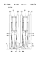
- FIG. 1 is an oblique projection showing a first embodiment of the multiple folding stage system.
- FIG. 2 is a lateral view of a first embodiment of the multiple folding stage system.
- FIG. 3 is a view of the first stage system when being folded.
- FIG. 4 is a view of the first stage system when stored against a wall area.
- FIG. 5 is a view of the second stage system when being folded.
- FIG. 6 is a view of the multiple folding stage system when stored against a wall area.
- FIG. 7 is an oblique projection showing posterior connection of the first stage system and the second stage system of the multiple folding stage system of the first embodiment.
- FIG. 8 is a lateral view of a second embodiment of the multiple folding stage system.
- FIG. 9 is a view of the multiple folding stage system the second embodiment when being folded.
- FIG. 10 is a view of the multiple folding stage system when stored against a wall area.
- FIG. 11 is a side view of the posterior connection of the multiple folding stage system a third embodiment.
- FIG. 12 is a view of the multiple folding stage system when stored against a wall area.
- the invention of an electrically-operated folding stage system includes a high-type system with comparatively long legs which are freely folded together. This system enables a multiple-version of folding stage system X1 and X2, more exactly a combination of X1 and X2 to be linked back and forth, folded up on a wall inside a building and compactly stored.
- This stage system shall be described in FIGS. 1 to 6 with respect to a first embodiment of the invention.
- FIGS. 1 to 6 shall be considered as the front and the left side as the rear.
- the stage system X1 which is illustrated as a front stage system (hereinafter referred to as "the first stage system), is composed of the front and rear stages S1 and S2, and the stage system X2 which is illustrated as a rear stage system (hereinafter referred to as "the second stage system). is composed of the front and rear stages S3 and S4.
- stages S1 and S2 of the abovementioned first stage system X1, and stages S3 and S4 of the second stage system X2, are covered with tatami mats T as shown in FIG. 1.
- Metal fittings 6 for stage legs 7 are fixed in the directions of depth and width of the platform 5, and are mounted together on the bottom of the first and second stage systems X1 and X2 as mentioned above.
- the metal fittings 6 are pivotally connected to the upper end of stage legs 7 so that legs 7 can be folded.
- link bars L1, L2, L3 and L4 are connected to the lower end of the stage legs 7.
- Link shafts placed over right to left across the width of the stage legs 7 pivotally support the legs 7 of each stage and the link bars L1 to L4.
- Wheel holders 8B to 8D respectively are fixed to the lower ends of stage legs 7B of the rearmost row of the front stage S2 of the first stage system X1, stage legs 7C of the foremost row of the front stage S3, and stage legs 7D of the rearmost row positioned under the rear stage S4 of the second stage system X2, except for stage legs 7A of the foremost row of the front stage S1 of the first stage system X1.
- These wheel holders pivotally support back and forth wheels 9 rotating on the indoor floor F.
- Adjustment legs 10 which can be freely adjusted for height are fixed to the lower ends of stage legs 7 of the front and rear stages S1 and S2 of the first stage system X1, except for stage legs 7A of the foremost row and stage legs 7A of the rearmost row, in order to keep the infolding first stage system X1 horizontal.
- wheels 11 which enable the second stage system X2 to be rotated back and forth are fixed to the lower ends of stage legs 7 of the front and rear stages S3 and S4 of the second stage system X2, except for stage legs 7D of the foremost row and stage legs 7D of the rearmost row.
- stage legs 7A of the foremost row of the front stage S1 are fixed to the floor F of a storage space so that the multiple folding stage system can be fixed, folded and stored in the storage space.
- the lower ends of stage legs 7A include the same wheels and holders as mentioned above so that the multiple folding stage system can be moved freely to the appropriate place.
- Components 12 are reinforcing plates for stage legs 7 and are fixed between adjoining stage legs 7 on the right and left.
- Component 13 is a link plate fixed to the back of the wheel holders 8D of the rearmost row of the second stage system X2. Link plate 13 entirely covers the lower part of the multiple folding stage system. At the same time, the link plate may protect the rearmost stage legs 7D positioned under the rear stage S4 of the second stage system X2 from its runout, or reinforce the frames and so forth.
- FIGS. 1 to 4 describe how stage legs 7 are arranged in three rows of front, middle and rear in the direction of depth of each stage S1 to S4. However, it may also be possible to fix four or five rows of stage legs 7 in the front and rear directions of depth of each stage S1 to S4 and in the right and left directions across the width so that each stage can be folded up and down.
- Numeral 21 denotes a stay projected from the end of link bar L2.
- one end of stay 21 may be fixed to one end of link bar L2 by welding or with bolts and nuts or the like.
- Numeral 22 denotes a link member such as a link, a rod, a turn buckle or the like which can be used freely to adjust the distance of the shafts, and one end of the link member 22 is placed between the right and left upper ends of stay 21 and keep it sustained together with link shaft 23. Also the other end of the link member 22 is connected to lower end of stage leg 7C and the head of link bar L3 and keep it sustained together with link shaft 24 placed across the width.
- Numeral 25 denotes a belt-shaped slide guide. Both sides of slide guide 25 are bent and fixed downward to the upper part of the wheel holder 8C connected to the stage leg 7C by using pin 26. A part of the slide guide 25 is connected through the upper part of the wheel holder 8B of the stage leg 7B. Guide rollers 27 are placed on the right and left of the upper part of the said wheel holder 8B. Guide rollers 28 are placed on the upper middle area of the wheel holder 8B. These guide rollers enable the lower part of the structure to be moved back and forth.
- link member 22 and link bars L1 to L4 are shown as fixed to the outside of stage legs 7B and 7C in order to make it easier to understand the structure. In fact, however, these features are fixed to the inside of stage legs 7B and 7C.
- stay 21 is vertically projected from the lower end of link bar L2 positioned under rear stage S2 of first stage system X1.
- the tip of stay 21 is fixed by link member 22 together with the front portion of link bar L3 positioned under front stage S3 of second stage system X2.
- first stage system X1 is pushed up (see FIG. 3), then folded together and stored against wall area K (see FIG. 4).
- the stay 21 rotates in a direction Q (FIG. 7) so that a distance "d" between stage legs 7B and 7C increases, there by producing a sufficient clearance between the first and second stage systems.
- second stage system X2 now begins rotating foreword on floor F in accordance with the movement of first stage system X. Following this movement as shown in FIG. 5, first stage system X1 is folded up and stored against wall area K.
- first stage system X1 of the multiple folding stage system and stage legs 7, 7A to 7D which are placed together on the lower part of front and rear stages S1 to S4 of second stage system X2, keep their upright positions as shown in FIGS. 3 to 6, move horizontally according to the folding movement of front and rear stages S1 to S4, then finally are pulled up vertically and gradually folded.
- first stage system X1 and second stage system X2 which are already folded and stored against wall area K are horizontally unfolded on floor F from wall area K, a reversal of the aforementioned processes occurs.
- electric motors M3 and M4 are reversed in order to rotate the output shaft in a reverse direction. This gradually generates the swing power to push open the output shaft at the supporting point of the lower end of swing arms A3 and A4.
- wheels 9 pivotally received by wheel holder 8D of stage leg 7D located in the foremost row of rear stage S4 are slowly rotated and pushed out.
- stage legs 7C, 7D and 7 which are folded between front and rear stages S3 and S4 keep their vertical position, move horizontally and gradually spread out.
- the opposed front and rear stages of second stage system X2 are horizontally unfolded on floor F.
- the second embodiment of the inventive multiple folding stage system is described herein based on FIGS. 8 to 10, in such a manner as to differentiate it from the aforementioned first embodiment.
- Numeral 31 denotes a stay which is projected slantingly behind the rear end of link bar L2 and numeral 32 denotes also a stay which is projected slantingly ahead of the front end of link bar L3. Both ends of stays 31 and 32 are pivotally connected by link shaft 33.
- Numeral 34 denotes an adjustment leg or pad which is fixed to the bottom of stage leg 7 positioned under second stage system X2. Other features are the same as in the aforementioned Embodiment No. 1. In this case, electric motors M1 and M2 of first stage system X1 and M3 and M4 of second stage system X2 positioned under the unfolded multiple folding stage system are started almost simultaneously.
- first stage system X1 and second stage system X2 are gradually parted and folded downward, then stored against wall area K.
- FIGS. 8 and 9 when folding the first stage system X1 and the second stage system X2, the distance between stage legs 7B and 7C increases by the rotation of stays 31 and 32, there by creating a sufficient space between the first stage system X1 and the second stage system X2.
- electric motors M1 to M4 fixed to first stage system X1 and second stage system X2 can be simultaneously operated to fold a number of stages. Therefore, it is not necessary to fix wheel 11 running on the floor F to stage leg 7 of second stage system X2, unlike the case in the first embodiment. Also, it is possible to store both first stage system X1 and second stage system X2 almost simultaneously, or else the time required to fold the stage systems may be reduced by as much as half compared to the first embodiment.
- the third embodiment of the inventive multiple folding stage system is described herein based on FIGS. 11 and 12 in such a manner as to differentiate it from the aforementioned the first embodiment.
- Numeral 41 denotes a stay projected from the rear end of link bar L2, and link shaft 42 is placed across stays widthways right and left.
- Numeral 43 denotes also a stay formed on the front end of link bar L3, and link shaft 44 is placed across stays widthways right and left.
- Numeral 45 denotes a link member such as a turn buckle which can be used freely to adjust space, and both ends of the rod penetrated the said link shafts 42 and 44 back and forth, in which the adjustment nut is tightened so that space can be freely adjusted.
- Other features are the same as in the aforementioned Embodiment No. 2, therefore description here is omitted as the same symbols are used.
- the distance between the first stage system X1 and the second stage system X2 changes such as shown eg. "d1" and "d2" of FIG. 11 to create the enough clearance therebetween.
- the multiple folding stage system, of the third embodiment is operated in the same manner as the second embodiment by almost simultaneously starting the electric motors M1 and M2 fixed to first stage system X1, and M3 and M4 fixed to second stage system X2 of the unfolded multiple folding stage system. Then as the imaginary line in FIG. 12 shows, the proximal surfaces of the posterior connection between first stage system X1 and second stage system X2 are gradually parted and folded downward. Thus a number of the stages are stored against a wall area K as shown in FIG. 12.
- electric motors M1 to M4 can be operated simultaneously to fold a number of stages. Therefore, it is possible to reduce the time required to store or unfold both first stage system X1 and second stage system X2 by as much as half compared to that of the first embodiment.
- the present invention -the multiple folding stage system consisting of the aforementioned structures--enables a number of stage systems to be folded smoothly and completely, without any inconveniences such as one system component pushing up another one, or one proximal surface cutting into another one.
- this system may be very convenient to use this system for sports training and games e.g. judo, gymnastics, kendo or the like, because such an unfolding movement makes the proximal surfaces of the posterior connection flusher with each other, and finally provides a complete large stage floor.
- stage floor of the multiple folding stage system is originally covered with tatami mats for judo or mats for gymnastics, it may not be necessary to place or take up these mats for every training event or game of judo or gymnastics, and athletes can concentrate on their practices or the like.
- this system can be compactly stored against a wall area inside a building.
- the invention of the multiple folding stage systems No. 1, No. 2 and No. 3 respectively can be utilized for judo, gymnastics and kendo.
- the building can also be used for other purposes such as a general gymnasium or the like. Therefore a gymnasium or other buildings can be used for multiple purposes, especially where there is great demand for school facilities or the like but where space is limited.
Landscapes
- Engineering & Computer Science (AREA)
- Architecture (AREA)
- Multimedia (AREA)
- Civil Engineering (AREA)
- Structural Engineering (AREA)
- Folding Of Thin Sheet-Like Materials, Special Discharging Devices, And Others (AREA)
- Handcart (AREA)
- Tents Or Canopies (AREA)
- Tables And Desks Characterized By Structural Shape (AREA)
- Air Bags (AREA)
- Auxiliary Devices For And Details Of Packaging Control (AREA)
- Electric Propulsion And Braking For Vehicles (AREA)
- Invalid Beds And Related Equipment (AREA)
- Warehouses Or Storage Devices (AREA)
- Electronic Switches (AREA)
- Roof Covering Using Slabs Or Stiff Sheets (AREA)
- Support Of Aerials (AREA)
- Floor Finish (AREA)
Applications Claiming Priority (2)
| Application Number | Priority Date | Filing Date | Title |
|---|---|---|---|
| JP26533597A JP3895841B2 (ja) | 1997-09-30 | 1997-09-30 | 多重折れステージ装置 |
| JP9-265335 | 1997-09-30 |
Publications (1)
| Publication Number | Publication Date |
|---|---|
| US6061970A true US6061970A (en) | 2000-05-16 |
Family
ID=17415765
Family Applications (1)
| Application Number | Title | Priority Date | Filing Date |
|---|---|---|---|
| US09/162,169 Expired - Lifetime US6061970A (en) | 1997-09-30 | 1998-09-29 | Electrically operated multiple folding stage system |
Country Status (10)
| Country | Link |
|---|---|
| US (1) | US6061970A (de) |
| EP (1) | EP0905333B1 (de) |
| JP (1) | JP3895841B2 (de) |
| KR (1) | KR100291341B1 (de) |
| CN (1) | CN1111637C (de) |
| AT (1) | ATE344863T1 (de) |
| DE (1) | DE69836364T2 (de) |
| ES (1) | ES2280088T3 (de) |
| PT (1) | PT905333E (de) |
| SE (1) | SE9053333T3 (de) |
Cited By (9)
| Publication number | Priority date | Publication date | Assignee | Title |
|---|---|---|---|---|
| US20040051344A1 (en) * | 2002-09-12 | 2004-03-18 | Per Erlandsson | Hinge apparatus for vehicle floor systems |
| US20050225044A1 (en) * | 2004-03-26 | 2005-10-13 | Brink Daniel J | Folding platform structure |
| US20110142591A1 (en) * | 2009-12-15 | 2011-06-16 | Production Resource Group L.L.C | Truss Hinge |
| US20130055647A1 (en) * | 2009-10-09 | 2013-03-07 | Giles Favell | Rostrum and support structure for a rostrum |
| CN103061547A (zh) * | 2013-01-17 | 2013-04-24 | 杭州佳合舞台设备有限公司 | 多维度动态舞台 |
| US9394708B2 (en) | 2013-03-01 | 2016-07-19 | Stageline Scene Mobile Inc. | Articulated floor structure for a mobile stage framework |
| CN106080780A (zh) * | 2016-06-23 | 2016-11-09 | 湘潭大学 | 一种基于麦克纳姆轮的体积可变运输平台及其操作方法 |
| WO2021050123A3 (en) * | 2019-05-31 | 2021-06-10 | Nolimits Enterprises, Inc. | Artificial intelligence for the classification of signals for radar detectors |
| ES2938786A1 (es) * | 2021-10-08 | 2023-04-14 | Palma Garcia Francisco | Tribuna plegable móvil |
Families Citing this family (11)
| Publication number | Priority date | Publication date | Assignee | Title |
|---|---|---|---|---|
| FR2810022B1 (fr) * | 2000-06-08 | 2004-10-22 | Euro Shelter | Conteneur deployable |
| WO2007010290A2 (en) * | 2005-07-22 | 2007-01-25 | Spatial Systems Limited | Apparatus for providing a variable surface |
| ES2368547B1 (es) * | 2009-02-18 | 2012-09-24 | El Cantillo, S.A. | Botella de vino con contacto permanente entre el vino y el corcho |
| JP5487039B2 (ja) * | 2010-07-27 | 2014-05-07 | フジタス工業株式会社 | ステージ装置 |
| US8920252B2 (en) | 2010-08-18 | 2014-12-30 | People Ent Co., Ltd. | Frame structure for stage erection |
| KR101065112B1 (ko) * | 2011-05-20 | 2011-09-16 | 상욱 김 | 스테이지 설치용 프레임 구조물 |
| NO337317B1 (no) | 2013-11-04 | 2016-03-07 | Ipi Access As | Sammenleggbar, langstrakt bærekonstruksjonsmodul og en sammenleggbar, langstrakt modulær bjelkekonstruksjon. |
| CN104806042B (zh) * | 2015-05-06 | 2017-03-01 | 北京信息科技大学 | 一种多板式自动折叠舞台及其控制方法 |
| CN106512444B (zh) * | 2016-12-07 | 2019-05-24 | 芜湖木木游乐设备有限公司 | 一种舞台用安全支撑装置 |
| CN110456421B (zh) * | 2018-05-08 | 2024-10-18 | 清华大学 | 折叠式车辆输送装置及车辆安全检测设备 |
| CN112502497B (zh) * | 2020-12-09 | 2021-11-09 | 杭州浙大中软智能科技有限公司 | 一种舞台结构 |
Citations (6)
| Publication number | Priority date | Publication date | Assignee | Title |
|---|---|---|---|---|
| US2978754A (en) * | 1959-11-16 | 1961-04-11 | Sico Mfg Co | Portable stage |
| US4872295A (en) * | 1988-03-25 | 1989-10-10 | Kazuo Fujita | Electrically-operated folding stage system |
| US5016403A (en) * | 1990-01-16 | 1991-05-21 | Kazuo Fujita | Electrically-operated folding stage system |
| US5069006A (en) * | 1989-04-13 | 1991-12-03 | Kazuo Fujita | Electrically-operated folding stage system |
| US5325640A (en) * | 1991-08-09 | 1994-07-05 | Sico Incorporated | Folding stage system |
| US5613450A (en) * | 1994-11-10 | 1997-03-25 | Sico Incorporated | Mobile folding stage |
Family Cites Families (7)
| Publication number | Priority date | Publication date | Assignee | Title |
|---|---|---|---|---|
| US3091816A (en) * | 1960-09-07 | 1963-06-04 | Wayne Iron Works | Folding stages |
| CA1126772A (en) * | 1979-02-01 | 1982-06-29 | Sico Incorporated | Support structure for mobile folding stage |
| US4779542A (en) * | 1987-07-31 | 1988-10-25 | Stageright Corporation | Fold and roll staging |
| JP2549561B2 (ja) * | 1989-09-06 | 1996-10-30 | 和夫 藤田 | 折り畳み式電動ステージ装置 |
| JP2704234B2 (ja) * | 1989-09-28 | 1998-01-26 | 和夫 藤田 | 折り畳み式電動ステージ装置 |
| JPH0721258A (ja) | 1993-06-23 | 1995-01-24 | Mitsubishi Materials Corp | 即時図上記録方法 |
| JPH07116855A (ja) | 1993-10-25 | 1995-05-09 | Mitsubishi Materials Corp | 溶断機 |
-
1997
- 1997-09-30 JP JP26533597A patent/JP3895841B2/ja not_active Expired - Lifetime
-
1998
- 1998-06-09 KR KR1019980021238A patent/KR100291341B1/ko not_active Expired - Fee Related
- 1998-09-07 SE SE98307208T patent/SE9053333T3/xx unknown
- 1998-09-07 EP EP98307208A patent/EP0905333B1/de not_active Expired - Lifetime
- 1998-09-07 ES ES98307208T patent/ES2280088T3/es not_active Expired - Lifetime
- 1998-09-07 AT AT98307208T patent/ATE344863T1/de active
- 1998-09-07 PT PT98307208T patent/PT905333E/pt unknown
- 1998-09-07 DE DE69836364T patent/DE69836364T2/de not_active Expired - Lifetime
- 1998-09-15 CN CN98119269A patent/CN1111637C/zh not_active Expired - Lifetime
- 1998-09-29 US US09/162,169 patent/US6061970A/en not_active Expired - Lifetime
Patent Citations (6)
| Publication number | Priority date | Publication date | Assignee | Title |
|---|---|---|---|---|
| US2978754A (en) * | 1959-11-16 | 1961-04-11 | Sico Mfg Co | Portable stage |
| US4872295A (en) * | 1988-03-25 | 1989-10-10 | Kazuo Fujita | Electrically-operated folding stage system |
| US5069006A (en) * | 1989-04-13 | 1991-12-03 | Kazuo Fujita | Electrically-operated folding stage system |
| US5016403A (en) * | 1990-01-16 | 1991-05-21 | Kazuo Fujita | Electrically-operated folding stage system |
| US5325640A (en) * | 1991-08-09 | 1994-07-05 | Sico Incorporated | Folding stage system |
| US5613450A (en) * | 1994-11-10 | 1997-03-25 | Sico Incorporated | Mobile folding stage |
Cited By (18)
| Publication number | Priority date | Publication date | Assignee | Title |
|---|---|---|---|---|
| US6719363B2 (en) * | 2002-09-12 | 2004-04-13 | Collins & Aikman Products Co. | Hinge apparatus for vehicle floor systems |
| US20040051344A1 (en) * | 2002-09-12 | 2004-03-18 | Per Erlandsson | Hinge apparatus for vehicle floor systems |
| US20050225044A1 (en) * | 2004-03-26 | 2005-10-13 | Brink Daniel J | Folding platform structure |
| US7210560B2 (en) * | 2004-03-26 | 2007-05-01 | Brink Daniel J | Folding platform structure |
| US20070273112A1 (en) * | 2004-03-26 | 2007-11-29 | Brink Daniel J | Folding platform structure |
| US20130055647A1 (en) * | 2009-10-09 | 2013-03-07 | Giles Favell | Rostrum and support structure for a rostrum |
| US8850774B2 (en) * | 2009-12-15 | 2014-10-07 | Production Resource Group Llc | Truss hinge for a stage truss |
| US20110142591A1 (en) * | 2009-12-15 | 2011-06-16 | Production Resource Group L.L.C | Truss Hinge |
| US9422972B2 (en) | 2009-12-15 | 2016-08-23 | Production Resource Group, Llc | Truss hinge with variations in angular settings |
| US9732511B2 (en) | 2009-12-15 | 2017-08-15 | Production Resource Group, Llc | Truss hinge with variations in angular settings |
| US9957709B2 (en) | 2009-12-15 | 2018-05-01 | Production Resource Group, Llc | Truss hinge with variations in angular settings |
| CN103061547A (zh) * | 2013-01-17 | 2013-04-24 | 杭州佳合舞台设备有限公司 | 多维度动态舞台 |
| US9394708B2 (en) | 2013-03-01 | 2016-07-19 | Stageline Scene Mobile Inc. | Articulated floor structure for a mobile stage framework |
| US9512629B2 (en) | 2013-03-01 | 2016-12-06 | Stageline Scene Mobile Inc. | Mobile stage framework and method of handling |
| CN106080780A (zh) * | 2016-06-23 | 2016-11-09 | 湘潭大学 | 一种基于麦克纳姆轮的体积可变运输平台及其操作方法 |
| CN106080780B (zh) * | 2016-06-23 | 2019-04-12 | 湘潭大学 | 一种基于麦克纳姆轮的体积可变运输平台及其操作方法 |
| WO2021050123A3 (en) * | 2019-05-31 | 2021-06-10 | Nolimits Enterprises, Inc. | Artificial intelligence for the classification of signals for radar detectors |
| ES2938786A1 (es) * | 2021-10-08 | 2023-04-14 | Palma Garcia Francisco | Tribuna plegable móvil |
Also Published As
| Publication number | Publication date |
|---|---|
| SE9053333T3 (de) | 2006-11-08 |
| JP3895841B2 (ja) | 2007-03-22 |
| ATE344863T1 (de) | 2006-11-15 |
| EP0905333B1 (de) | 2006-11-08 |
| DE69836364D1 (de) | 2006-12-21 |
| JPH11107559A (ja) | 1999-04-20 |
| CN1213035A (zh) | 1999-04-07 |
| KR19990029219A (ko) | 1999-04-26 |
| ES2280088T3 (es) | 2007-09-01 |
| DE69836364T2 (de) | 2007-03-08 |
| HK1019350A1 (en) | 2000-02-03 |
| EP0905333A1 (de) | 1999-03-31 |
| CN1111637C (zh) | 2003-06-18 |
| PT905333E (pt) | 2007-01-31 |
| KR100291341B1 (ko) | 2001-06-01 |
Similar Documents
| Publication | Publication Date | Title |
|---|---|---|
| US6061970A (en) | Electrically operated multiple folding stage system | |
| KR102497775B1 (ko) | 경사조절이 가능한 인공암벽 | |
| JPH02194277A (ja) | 折り畳み式電動ステージ装置 | |
| JPH02274973A (ja) | 電動ステージ装置 | |
| JP2549558B2 (ja) | 電動ステージ装置 | |
| JPH02136106A (ja) | 移動観覧席の座席起立装置 | |
| US5271190A (en) | Apparatus for opening and closing covering means for furniture raising/lowering type floor equipment | |
| JPS6316777Y2 (de) | ||
| JP3779451B2 (ja) | 移動観覧席 | |
| EP0492643B1 (de) | Apparat zum Stellen der Betriebsposition von Möbel in eine Möbel-Versenkeinrichtung | |
| JP2704234B2 (ja) | 折り畳み式電動ステージ装置 | |
| CN221137801U (zh) | 一种座椅支撑调节结构 | |
| KR200413128Y1 (ko) | 접철식 골프 연습장 | |
| CN116650906B (zh) | 跑台用坡度调节机构 | |
| CN222708904U (zh) | 一种联动折叠哑铃凳 | |
| JPH01187268A (ja) | 折り畳み式電動ステージ装置 | |
| EP0488308A1 (de) | Apparat zum Öffnen und Schliessen von Abdeckungen in einer Möbel-Versenkeinrichtung | |
| JP2549561B2 (ja) | 折り畳み式電動ステージ装置 | |
| JP2549562B2 (ja) | 折り畳み式電動ステージ装置 | |
| JPH0650024B2 (ja) | 電動ステージ装置 | |
| JPH0998853A (ja) | 折り畳み式ベッド | |
| JP3134831B2 (ja) | 移動観覧席 | |
| JP2661585B2 (ja) | 移動観覧席 | |
| SU586263A1 (ru) | Трибуна | |
| CN116950539A (zh) | 一种大型电动隔断门及其安装方法 |
Legal Events
| Date | Code | Title | Description |
|---|---|---|---|
| STCF | Information on status: patent grant |
Free format text: PATENTED CASE |
|
| FPAY | Fee payment |
Year of fee payment: 4 |
|
| FPAY | Fee payment |
Year of fee payment: 8 |
|
| FPAY | Fee payment |
Year of fee payment: 12 |