US6063018A - Centrifuge having force responsive locking device for securing a rotor to a drive head - Google Patents
Centrifuge having force responsive locking device for securing a rotor to a drive head Download PDFInfo
- Publication number
- US6063018A US6063018A US09/166,955 US16695598A US6063018A US 6063018 A US6063018 A US 6063018A US 16695598 A US16695598 A US 16695598A US 6063018 A US6063018 A US 6063018A
- Authority
- US
- United States
- Prior art keywords
- rotor
- drive head
- centrifuge
- weights
- drive
- Prior art date
- Legal status (The legal status is an assumption and is not a legal conclusion. Google has not performed a legal analysis and makes no representation as to the accuracy of the status listed.)
- Expired - Lifetime
Links
Images

Classifications
-
- B—PERFORMING OPERATIONS; TRANSPORTING
- B04—CENTRIFUGAL APPARATUS OR MACHINES FOR CARRYING-OUT PHYSICAL OR CHEMICAL PROCESSES
- B04B—CENTRIFUGES
- B04B9/00—Drives specially designed for centrifuges; Arrangement or disposition of transmission gearing; Suspending or balancing rotary bowls
- B04B9/08—Arrangement or disposition of transmission gearing ; Couplings; Brakes
-
- B—PERFORMING OPERATIONS; TRANSPORTING
- B04—CENTRIFUGAL APPARATUS OR MACHINES FOR CARRYING-OUT PHYSICAL OR CHEMICAL PROCESSES
- B04B—CENTRIFUGES
- B04B7/00—Elements of centrifuges
- B04B7/02—Casings; Lids
- B04B2007/025—Lids for laboratory centrifuge rotors
-
- B—PERFORMING OPERATIONS; TRANSPORTING
- B04—CENTRIFUGAL APPARATUS OR MACHINES FOR CARRYING-OUT PHYSICAL OR CHEMICAL PROCESSES
- B04B—CENTRIFUGES
- B04B9/00—Drives specially designed for centrifuges; Arrangement or disposition of transmission gearing; Suspending or balancing rotary bowls
- B04B9/08—Arrangement or disposition of transmission gearing ; Couplings; Brakes
- B04B2009/085—Locking means between drive shaft and rotor
-
- Y—GENERAL TAGGING OF NEW TECHNOLOGICAL DEVELOPMENTS; GENERAL TAGGING OF CROSS-SECTIONAL TECHNOLOGIES SPANNING OVER SEVERAL SECTIONS OF THE IPC; TECHNICAL SUBJECTS COVERED BY FORMER USPC CROSS-REFERENCE ART COLLECTIONS [XRACs] AND DIGESTS
- Y10—TECHNICAL SUBJECTS COVERED BY FORMER USPC
- Y10T—TECHNICAL SUBJECTS COVERED BY FORMER US CLASSIFICATION
- Y10T403/00—Joints and connections
- Y10T403/60—Biased catch or latch
- Y10T403/602—Biased catch or latch by separate spring
-
- Y—GENERAL TAGGING OF NEW TECHNOLOGICAL DEVELOPMENTS; GENERAL TAGGING OF CROSS-SECTIONAL TECHNOLOGIES SPANNING OVER SEVERAL SECTIONS OF THE IPC; TECHNICAL SUBJECTS COVERED BY FORMER USPC CROSS-REFERENCE ART COLLECTIONS [XRACs] AND DIGESTS
- Y10—TECHNICAL SUBJECTS COVERED BY FORMER USPC
- Y10T—TECHNICAL SUBJECTS COVERED BY FORMER US CLASSIFICATION
- Y10T403/00—Joints and connections
- Y10T403/60—Biased catch or latch
- Y10T403/608—Pivoted
Definitions
- the present invention concerns a centrifuge comprising a rotational drive head attached to a rotation shaft, a rotor adapted to be removably mounted on the drive head in a rotational driving position, coupling means for coupling the drive head and the rotor in rotation, and a locking device for axially locking the rotor to the drive head comprising means for applying to the rotor an axial retaining force for retaining a bearing surface of the rotor against a retaining surface fastened to the drive head.
- Centrifuges of the above kind are used in particular in the biological field for centrifuging products contained in containers disposed in housings formed in the rotor.
- a drive head of a centrifuge of the above kind generally has a vertical axis and extends the upper part of a drive shaft.
- a corresponding rotor is provided with an opening at the bottom to receive the head.
- the head When the rotor is rotated by the drive head, the head is subjected to forces that tend to separate it axially from the drive head and to cause it to lift off.
- a user can separate the rotor and the drive head manually using the actuator member and compressing the coil spring.
- the axial retaining force is constant and limited to values enabling manual use of the actuator member.
- the axial retaining force can prove insufficient, in particular at high rotation speeds, like those encountered in ultracentrifuges, which can be as high as 150 000 rpm.
- centrifuge described in document WO 83/04379 involves using a lid closing the rotor to assure the axial locking of the rotor to the drive head, which complicates the operations of mounting the rotor on the drive head and demounting it therefrom.
- An aim of the invention is to solve the above problems by providing a centrifuge whose axial locking device caters for a wide range of drive head rotation speeds and simplifies the operations of mounting the rotor on the drive head and demounting it therefrom.
- the invention consists in a centrifuge comprising a rotational drive head attached to a rotation shaft, a rotor adapted to be removably mounted on the drive head in a rotational driving position, coupling means for coupling the drive head and the rotor in rotation, and a locking device for axially locking the rotor to the drive head comprising means for applying to the rotor an axial retaining force for retaining a bearing surface of the rotor against a retaining surface fastened to the drive head, characterised in that the means for applying a retaining force are means for applying a retaining force that increases with the rotational speed of the drive head.
- the means for applying a retaining force comprise at least two inertia weights mounted symmetrically relative to the rotation axis of the drive head on an end part of the drive head.
- Each weight is movable between a position of axial unlocking of the rotor and the drive head, in which the weight is retracted into the drive head, and a position of axial locking of the rotor to the drive head in accordance with the rotation speed of the drive head, wherein a thrust part of the weight projects relative to a radially outermost surface of the drive head and cooperates with a ramp surface of an opening receiving the end part of the drive head formed in the rotor.
- the ramp surface is inclined towards the inside of the opening and towards the bearing surface of the rotor;
- the ramp surface is substantially frustoconical
- At least one weight its spring-loaded from is retracted position towards a position of initial axial locking of the rotor to the drive head;
- the weights are mounted to rotate on the end part of the drive head and each includes a manoeuvring appendix adapted to be actuated simultaneously by an external member when the rotor is in the drive position to return the weights to their retracted positions of axial unlocking of the rotor and the drive head;
- the bearing surface of the rotor and the retaining surface of the drive head are substantially frustoconical and conjugate, the retaining surface forming a surface for centring the rotor on the drive head;
- At least one weight is an impact weight to generate an audible signal upon axial locking of the rotor to the drive head.
- the invention also consists in a rotor for a centrifuge as defined hereinabove characterized in that it comprises an opening receiving at least one end part of a drive head of a centrifuge with the opening having a surface bearing against a retaining surface fastened to the drive head and at least one ramp surface adapted to cooperate with a thrust part of a weight of the drive head.
- the ramp surface is inclined towards the inside of the opening and towards the bearing surface.
- the ramp surface is substantially frustoconical
- the bearing surface is substantially frustoconical.
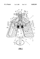
- FIG. 1 is a part-sectional side view of a centrifuge in accordance with the invention, the drive head being shown in side view,
- FIGS. 2, 3 and 4 are views of the drive head of the centrifuge from FIG. 1 in section taken along the line II--II in FIG. 1 and respectively showing the weights in an initial locking position, in a locking position when the drive head is rotating and in an unlocking position, and
- FIG. 5 is a view similar to FIG. 1 showing the use of a rotor with no lid.
- FIG. 1 shows part of a centrifuge 1 essentially comprising a drive head 2, a rotor 3 mounted in the driving position on the drive head 2, a removable lid 4 closing the rotor 3 and an actuator member 5 attached to the lid 4.
- the rotor 3 is generally frustoconical in shape, converging towards a top face 6 of the rotor 3 (as seen in FIG. 1) and is made of aluminum, for example.
- a stepped bore 7 coaxial with the rotor 3 passes through it.
- the bore 7 is delimited, in succession from a bottom face 8 of the rotor 3, by a frustoconical bearing surface 9 converging towards the top surface 6, a cylindrical surface 10, a frustoconical ramp surface 11 diverging towards the top surface 6, and two successive cylindrical surfaces 12 and 13 of relatively greater diameter and relatively smaller diameter, respectively, linked by a shoulder 14 substantially orthogonal to the axis of the rotor 3.
- the ramp surface 11 is inclined towards the inside of the bore 7 and towards the bearing surface 9.
- the ramp surface 11, the cylindrical surface 12 and the shoulder 14 delimit an annular groove 15.
- the angle of convergence of the bearing surface 9 relative to the axis of the rotor 3 is approximately 30°.
- the angle of divergence of the ramp surface 11 relative to the axis of the rotor 3 is approximately 75°.
- the top surface 6 has a annular peripheral rim 16 projecting axially relative to the surface 6.
- the rotor 3 incorporates housings 100 (only one of which is shown in FIG. 1) opening onto the surface 6 for ampoules or other containers designed to contain products to be centrifuged.
- a stepped cylindrical cap 17 is fixed by a flange 18 to the top surface 6 of the rotor 3, coaxially therewith.
- a cylindrical bottom part 19 of the cap 17 is received with a small clearance in the part of the bore 7 delimited by the cylindrical surface 13. The cap 17 closes off the bore 7.
- the bottom surface 20 of the part 19 of the cap 17, which is substantially orthogonal to the axis of the rotor 3, is provided with two rotational coupling pins 21 projecting axially relative to the surface 20 and diametrically opposed to each other relative to the axis of the rotor 3.
- a central stepped bore 22 through the cap 17 comprises a screwthreaded cylindrical part 23 at the top (as seen in FIG. 1) of relatively larger diameter and a cylindrical part 24 at the bottom of relatively smaller diameter.
- the lid 4 is generally frustoconical in shape and has on its bottom surface 25 (as seen in FIG. 1) a peripheral rim 26 projecting axially from the surface 25.
- the lid 4 is removably fixed and sealed to the rotor 3 in a manner described hereinafter.
- the rim 26 on the lid 4 fits inside the rim 16 on the rotor 3 and the lid 4 is coaxial with the rotor 3.
- the actuator member 5 shown in a rest position in FIG. 1, comprises a cylindrical body 28 with a central bore 29 through it, a rod 30 sliding in the bore 29 and a knob 31 attached to the cylindrical body 28.
- the bottom part of the body 28 is externally screwthreaded.
- the top end of the rod 30 is extended by a button 32 coaxial with the rod 30.
- a bottom face 33 of the button 32 substantially orthogonal to the axis of the rod 30, and having a diameter greater than that of the rod 30 is attached to the rod 30.
- the rod 30 has a transverse groove in its outside surface receiving a spring washer 34.
- the bottom end 35 of the rod 30 is tapered.
- a spring 36 is threaded over the rod 30 and bears on a top surface 37 of the body 28 and on the bottom surface 33 of the button 32.
- the knob 31 is in the form a stepped cylinder with a central bore 39 though it receiving a top part of the body 28, the spring 36 and a bottom part of the button 32.
- the body 28 is fixed coaxially to the knob 31.
- the spring 36 and the bottom part of the button 32 can slide in the bore 39.
- the relatively larger diameter top part 40 of the knob 31 is knurled.
- the actuator member 5 is symmetrical about a longitudinal axis.
- the body 28 passes through the opening 27 and is fixed to the lid 4 to seal the opening 27.
- the rotor 3, the lid 4 and the actuator member 5 are coaxial.
- the bottom part of the body 28 is screwed into the part 23 of the bore 22 in the cap 17 to fix the lid 4 to the rotor 3.
- a top part of the button 32 projects relative to a top surface 41 of the knob 31 and the tapered end 35 of the rod 30 projects axially below the bottom surface 20 of the cap 17, the rod 30 passing though the bore 29 and the bore 22.
- the spring washer 34 bears against the bottom surface of the body 28 and the spring 36 is slightly compressed.
- the drive head is symmetrical about an axis 42 and is fixed to the top end of a vertical rotation shaft 43 of the centrifuge 1, coaxially therewith.
- the rotational axis of the rotation shaft 43 and of the drive head 2 is coincident with the axis 42 and is shown in dotted line in FIG. 1.
- the drive head 2 comprises, in succession, a cylindrical part 44 for coupling it to the drive shaft 43, a frustoconical part 45 converging towards a top surface 46 of the head 2 and delimited by a retaining surface 47, and a generally cylindrical upper end part 48 delimited at the top by the surface 46 that is substantially orthogonal to the axis 42.
- the diameter of the cylindrical part 44 is less than the greatest diameter of the frustoconical part 45 and the radially outermost surface 49 of the part 48 extends the retaining surface 47.
- the angle of convergence of the retaining surface 47 relative to the axis 42 is approximately 30° and corresponds to the angle of convergence of the bearing surface 9 of the rotor 3.
- Two identical recesses 51 are formed in the cylindrical part 48 at substantially equal distances from the upper edge of the retaining surface 47 and from the surface 46, and symmetrically about a plane 52 (FIG. 2) passing through the axis 42 and orthogonal to the plane of FIG. 1.
- the recesses 51 are cylindrical, their axis is parallel to the axis 42 and their base is a segment of a circle.
- the recesses 51 delimit between them a vertical central wall 53.
- a transverse opening 54 through the wall 53 has an axis orthogonal to the plane 52 and a rectangular base.
- a vertical blind bore 55 coaxial with the head 2 and opening onto the surface 46 passes through the wall 43 of the cylindrical part 48. This bore extends into the wall 53 below the opening 54. The diameter of the bore 55 is substantially equal to the outside diameter of the rod 30 of the actuator member 5.
- the drive head 2 includes two identical weights 56.
- Each weight 56 has a body 57 with a shape corresponding to that of the recesses 51 and an actuator spur 58 extending the corresponding body 57 in an upper part of its plane lateral face 59.
- the weights 56 are made of bronze or stainless steel, for example.
- Each weight 56 is mounted to rotate on the drive head 2 in recess 51 by means of pins 61 with axes parallel to the axis 42 and each passing through one of the recesses 51.
- the weights 56 are symmetrically disposed relative to the axis 42.
- the pins 61 are offset relative to the plane 62 (the plane of FIG. 1) orthogonal to the plane 52 and passing through the axis 42.
- the spurs 58 are received in the opening 54 in the wall 53.
- Return coil springs 63 are disposed at a distance from the pins 61 between each weight 56 and the wall 53.
- the weights 56 have curved lateral thrust surfaces 64 the top edge 65 of which is chamfered (FIG. 1) and the bottom edge 66 of which is rounded.
- the surface 46 of the head 2 has two rotational coupling pins 67 projecting axially from the surface 46 and diameterally opposed to each other relative to the axis 42.
- Each weight 56 can rotate about the pins 61 between a position of axial unlocking of the rotor 3 and the drive head 2 and a position of axial locking of the rotor 3 to the head 2 dependent on the rotation speed of the drive head, as explained below.
- the thrust surfaces 64 extend the outside surface 49 of the part 48, the weights 56 being retracted into the head 2 at this time.
- the spurs 58 of the weights 56 are tangential to the cylindrical surface delimiting the bore 55.
- the springs 63 are compressed.
- the thrust surfaces 64 of the weights 56 project relative to the surface 49 of the part 48.
- the spurs 58 of the weights 56 are inside the cylindrical surface delimiting the bore 55.
- a user proceeds as follows, for example.
- the user places containers containing products to be centrifuged in the housings 100 and then fixes the lid 4 to the rotor 3 using the knob 31, screwing on the body 28 of the actuator member 5.
- the knurling of the part 40 of the knob 31 gives a good grip on the knob 31.
- the weights 56 are initially in a position between the positions shown in FIGS. 2 and 3 and the springs 63 are not compressed.
- the weights 56 reach their unlocking position simultaneously when the thrust surfaces 64 are in contact with the cylindrical surface 10 of the bore 7 in the rotor 3.
- the retaining surface 47 of the drive head 2 centers the rotor 3 on the head 2.
- the rotor 3 is then mounted on the drive head 2 in the drive position shown in FIG. 1.
- the rotor 3 and the drive head 2 are then coaxial.
- This axial locking is sufficient for rotation of the rotor 3 to begin in total safety.
- the thrust surfaces 44 progressively move radially outwards, projecting relative to the surface 49 of the part 48. Acting as cams, the weights 56 push the rotor 3 downwards, applying an axial retaining force that increases with the rotation speed of the drive head 2.
- the user can then remove the rotor 3 from the drive head 2 by lifting it off using the knob 31 of the actuator member 5.
- the angle of convergence of the frustoconical surfaces 9 and 47 prevents binding of the rotor 3 on the drive head 2 and thereby facilitates demounting of the rotor 3, all the more so in that the increasing retaining force of the rotor 3 on the head 2 substantially compensates the lifting force operating on the rotor 3 when it rotates.
- the angle of convergence of the conjugate frustoconical surfaces 9 and 47 can be in the range 25° to 45°.
- the angle of divergence of the ramp surface 11 can be in the range 70° to 80°.
- the axial locking device of the centrifuge in FIG. 1 is entirely inside the drive head 2 and therefore has the advantage of enabling the use of a rotor 1 without its lid as shown in FIG. 4.
- the centrifuge 1 in FIG. 5 differs from that in FIG. 1 in that the lid 4 has been removed from the rotor 3 and in that the rod 30 and the knob 31 of the actuator member 5 are in one piece with the body 28. A transverse bar through the knob 31 makes it easier to grip.
- the mounting, rotational driving and axial locking of the rotor 3 on the drive head 2 are similar to those described with reference to FIG. 1.
- the user can then remove the rotor 3 from the drive head 2, for example using the knob 31 of the actuator member 5 to lift off the rotor 3.
- This feature simplifies mounting/demounting the rotor 3 on the drive head 2, in particular for users requiring to centrifuge sealed tubes at low speeds.
Landscapes
- Centrifugal Separators (AREA)
Applications Claiming Priority (2)
| Application Number | Priority Date | Filing Date | Title |
|---|---|---|---|
| FR9713308A FR2770154B1 (fr) | 1997-10-23 | 1997-10-23 | Centrifugeuse a rotor demontable et a dispositif de blocage axial du rotor sur une tete d'entrainement, et rotor pour une telle centrifugeuse |
| FR9713308 | 1997-10-23 |
Publications (1)
| Publication Number | Publication Date |
|---|---|
| US6063018A true US6063018A (en) | 2000-05-16 |
Family
ID=9512573
Family Applications (1)
| Application Number | Title | Priority Date | Filing Date |
|---|---|---|---|
| US09/166,955 Expired - Lifetime US6063018A (en) | 1997-10-23 | 1998-10-06 | Centrifuge having force responsive locking device for securing a rotor to a drive head |
Country Status (7)
| Country | Link |
|---|---|
| US (1) | US6063018A (fr) |
| EP (1) | EP0911080B1 (fr) |
| JP (1) | JP4239119B2 (fr) |
| AT (1) | ATE229375T1 (fr) |
| DE (1) | DE69810060T2 (fr) |
| ES (1) | ES2189110T3 (fr) |
| FR (1) | FR2770154B1 (fr) |
Cited By (36)
| Publication number | Priority date | Publication date | Assignee | Title |
|---|---|---|---|---|
| US20030196310A1 (en) * | 2002-04-22 | 2003-10-23 | Kendro Laboratory Products | Cover attachment method and apparatus |
| US6665924B2 (en) * | 2002-01-25 | 2003-12-23 | Kendro Laboratory Products, L.P. | Centrifuge having a spring-loaded nut for securing a rotor to a drive cone |
| US20040018928A1 (en) * | 2002-04-22 | 2004-01-29 | Klaus Schutz | Easy access cover |
| US6764438B2 (en) * | 2002-04-22 | 2004-07-20 | Kendro Laboratory Products, Lp | Cover attachment apparatus |
| US6776751B2 (en) * | 2002-04-22 | 2004-08-17 | Kendor Laboratory Products, Lp | Rotor cover attachment apparatus |
| US7011618B2 (en) * | 2003-05-16 | 2006-03-14 | Kendro Laboratory Products Lp | Attachment and release apparatus for a centrifuge rotor cover |
| US20060058169A1 (en) * | 2004-09-15 | 2006-03-16 | Souichirou Matusima | Rotor mounting structure for centrifugal separator |
| GB2424607A (en) * | 2005-03-29 | 2006-10-04 | Kendro Lab Prod Gmbh | Centrifuge lid engagement arrangement |
| US20060279714A1 (en) * | 2005-06-10 | 2006-12-14 | Stahl Kurt A | Integrated light gathering reflector and optical element holder |
| WO2007134624A1 (fr) * | 2006-05-23 | 2007-11-29 | Eppendorf Ag | Couvercle servant à fermer le rotor d'une centrifugeuse |
| US20080146429A1 (en) * | 2006-12-13 | 2008-06-19 | Thermo Electron Corporation | Rotor assembly and method of connection thereof |
| WO2010025922A1 (fr) * | 2008-09-03 | 2010-03-11 | Thermo Electron Led Gmbh | Centrifugeur pourvu d'un élément d'accouplement pour le verrouillage axial d'un rotor |
| US20110183830A1 (en) * | 2008-08-18 | 2011-07-28 | Boll & Kirch Filterbau Gmbh | Centrifuge and centrifuge rotor for the same |
| CN102405108A (zh) * | 2009-06-30 | 2012-04-04 | 株式会社久保田制作所 | 转鼓用盖部机构 |
| WO2012059151A1 (fr) * | 2010-11-01 | 2012-05-10 | Sigma Laborzentrifugen Gmbh | Montage de rotor sur palier pour une centrifugeuse de laboratoire |
| US20130203581A1 (en) * | 2009-11-04 | 2013-08-08 | Awel International | Centrifuge integrating tachometric device mounted in an upper part of the chamber, especially mounted on the lid |
| US20130237399A1 (en) * | 2009-11-04 | 2013-09-12 | Awel International | Centrifuge comprising visual and/or tactile indicator for indicating the accurate mounting of the rotor on the drive shaft, and corresponding rotor |
| US20130331253A1 (en) * | 2012-06-08 | 2013-12-12 | Thermo Electron Led Gmbh | Centrifuge Drive Head For Releasably Connecting A Driving System To A Rotor Of A Centrifuge, A Set And A Centrifuge Comprising The Drive Head |
| CN103481428A (zh) * | 2013-09-09 | 2014-01-01 | 湖南恒科新材料有限公司 | 一种离心机用防抱死装置 |
| US20140329658A1 (en) * | 2013-05-02 | 2014-11-06 | Afi Centrifuge | Laboratory centrifuge comprising means for the locking in translation of a rotor on a driving motor shaft |
| US20150231648A1 (en) * | 2014-02-17 | 2015-08-20 | Thermo Electron Led Gmbh | Drive Head For Detachable Connection Of A Drive With A Rotor Of A Centrifuge, Kit Comprising Such A Drive Head, And Centrifuge |
| US20150343459A1 (en) * | 2014-05-28 | 2015-12-03 | Thermo Electron Led Gmbh | Drive Head For Detachable Connection Of A Drive With A Rotor Of A Centrifuge, Kit Comprising The Drive Head, And Centrifuge |
| US20160107171A1 (en) * | 2014-10-21 | 2016-04-21 | Sigma Laborzentrifugen Gmbh | Coupling Device for a Laboratory Centrifuge Actuated by Centrifugal Force |
| US20170014784A1 (en) * | 2011-04-07 | 2017-01-19 | Life Technologies Corporation | System and methods for making and processing emulsions |
| US20170050195A1 (en) * | 2015-08-20 | 2017-02-23 | Andreas Hettich Gmbh & Co. Kg | Centrifuge rotor |
| US20170050194A1 (en) * | 2015-08-20 | 2017-02-23 | Andreas Hettich Gmbh & Co. Kg | Centrifuge rotor |
| US20170252754A1 (en) * | 2014-08-29 | 2017-09-07 | Andreas Hettich Gmbh & Co. Kg | Quick closure for a centrifuge |
| US10300499B2 (en) * | 2013-07-18 | 2019-05-28 | Andreas Hettich Gmbh & Co. Kg | Centrifuge with removable rotor |
| US10532366B2 (en) * | 2016-07-13 | 2020-01-14 | Kubota Manufacturing Corporation | Rotor attachment structure and centrifuge |
| CN111659546A (zh) * | 2020-04-24 | 2020-09-15 | 青岛海尔生物医疗股份有限公司 | 一种离心机 |
| CN113731651A (zh) * | 2020-05-29 | 2021-12-03 | 费柏莱特离心机有限公司 | 用于平衡离心机转子的系统和方法 |
| CN114405693A (zh) * | 2021-12-02 | 2022-04-29 | 深圳市瑞沃德生命科技有限公司 | 一种驱动轴、转子及其离心机 |
| US11731144B2 (en) * | 2017-12-20 | 2023-08-22 | Eppendorf Se | Centrifuge rotor with locking levers providing visual indication of cover closure |
| US11986842B2 (en) | 2018-06-14 | 2024-05-21 | Andreas Hettich Gmbh & Co. Kg | Centrifuge |
| EP4487961A1 (fr) | 2023-07-04 | 2025-01-08 | Sigma Laborzentrifugen GmbH | Centrifugeuse, rotor pour centrifugeuse et tête d'entraînement pour centrifugeuse |
| FR3158894A1 (fr) | 2024-02-06 | 2025-08-08 | Sarl Afi Centrifuge | Ensemble rotor pour centrifugeuse de laboratoire. |
Families Citing this family (5)
| Publication number | Priority date | Publication date | Assignee | Title |
|---|---|---|---|---|
| JP3861476B2 (ja) * | 1998-09-30 | 2006-12-20 | 日立工機株式会社 | 遠心分離機 |
| JP5442337B2 (ja) * | 2009-06-30 | 2014-03-12 | 株式会社久保田製作所 | 遠心分離機、遠心分離機用ロータ |
| DE102015113856A1 (de) | 2015-08-20 | 2017-02-23 | Andreas Hettich Gmbh & Co. Kg | Rotor einer Zentrifuge |
| WO2017136225A1 (fr) * | 2016-02-01 | 2017-08-10 | Vermeer Manufacturing Company | Rotors à équilibrage automatique permettant de fragmenter un matériau et procédés permettant d'équilibrer des rotors |
| CN111659547B (zh) * | 2020-04-24 | 2024-09-06 | 青岛海特生物医疗有限公司 | 离心机转子 |
Citations (19)
| Publication number | Priority date | Publication date | Assignee | Title |
|---|---|---|---|---|
| DE284366C (fr) * | ||||
| DD36013A1 (de) * | 1964-05-16 | 1965-02-25 | Rotor mit ausschwingbaren Bechereinsätzen für Zentrifugen | |
| US3819111A (en) * | 1973-04-09 | 1974-06-25 | Sorvall Inc Ivan | Centrifuge rotor cover |
| US3961745A (en) * | 1974-04-08 | 1976-06-08 | Beckman Instruments, Inc. | Centrifuge apparatus |
| US4010890A (en) * | 1976-01-28 | 1977-03-08 | Beckman Instruments, Inc. | Centrifuge rotor lid |
| DE2907789A1 (de) * | 1978-02-28 | 1979-08-30 | Rydborn S A O | Verriegelungsvorrichtung |
| US4344563A (en) * | 1980-12-23 | 1982-08-17 | E. I. Du Pont De Nemours And Company | Centrifuge rotor having vertically offset trunnion pins |
| US4360151A (en) * | 1980-07-01 | 1982-11-23 | Beckman Instruments, Inc. | Aerosol resistant bowl rotor |
| US4412830A (en) * | 1982-06-24 | 1983-11-01 | Beckman Instruments, Inc. | Cover for centrifuge rotor |
| WO1983004379A1 (fr) * | 1982-06-09 | 1983-12-22 | Beckman Instruments, Inc. | Assemblage d'attache d'un rotor de centrifugeuse |
| US4435169A (en) * | 1982-09-29 | 1984-03-06 | E. I. Du Pont De Nemours And Company | Centrifuge rotor having a closable windshield |
| US4753631A (en) * | 1986-11-03 | 1988-06-28 | E. I. Du Pont De Nemours And Company | Speed limiting arrangement for a centrifuge rotor having an axial mounting bolt |
| US4850951A (en) * | 1988-07-01 | 1989-07-25 | Beckman Instruments, Inc. | Lid retention apparatus for coverage centrifuge rotors |
| US5344380A (en) * | 1992-09-30 | 1994-09-06 | Beckman Instruments, Inc. | Release handle for centrifuge rotor and lid |
| JPH07861A (ja) * | 1993-06-18 | 1995-01-06 | Hitachi Koki Co Ltd | 遠心分離機 |
| DE9416937U1 (de) * | 1994-10-21 | 1995-11-16 | Fa. Andreas Hettich, 78532 Tuttlingen | Rotoranordnung für Zentrifugen |
| EP0712667A1 (fr) * | 1994-11-21 | 1996-05-22 | JOUAN, Société Anonyme dite | Centrifugeuse à rotor démontable et à dispositif de blocage axial du rotor sur l'arbre d'entraînement |
| US5683341A (en) * | 1996-03-14 | 1997-11-04 | Piramoon Technologies, Inc. | Quill shaft suspension for centrifuge rotor having central stator |
| US5897482A (en) * | 1998-03-04 | 1999-04-27 | Beckman Instruments, Inc. | Rotor lid tie-down and vacuum venting system |
-
1997
- 1997-10-23 FR FR9713308A patent/FR2770154B1/fr not_active Expired - Fee Related
-
1998
- 1998-10-02 EP EP98402433A patent/EP0911080B1/fr not_active Expired - Lifetime
- 1998-10-02 DE DE69810060T patent/DE69810060T2/de not_active Expired - Lifetime
- 1998-10-02 AT AT98402433T patent/ATE229375T1/de not_active IP Right Cessation
- 1998-10-02 ES ES98402433T patent/ES2189110T3/es not_active Expired - Lifetime
- 1998-10-06 US US09/166,955 patent/US6063018A/en not_active Expired - Lifetime
- 1998-10-23 JP JP30240298A patent/JP4239119B2/ja not_active Expired - Lifetime
Patent Citations (20)
| Publication number | Priority date | Publication date | Assignee | Title |
|---|---|---|---|---|
| DE284366C (fr) * | ||||
| DD36013A1 (de) * | 1964-05-16 | 1965-02-25 | Rotor mit ausschwingbaren Bechereinsätzen für Zentrifugen | |
| US3819111A (en) * | 1973-04-09 | 1974-06-25 | Sorvall Inc Ivan | Centrifuge rotor cover |
| US3961745A (en) * | 1974-04-08 | 1976-06-08 | Beckman Instruments, Inc. | Centrifuge apparatus |
| US4010890A (en) * | 1976-01-28 | 1977-03-08 | Beckman Instruments, Inc. | Centrifuge rotor lid |
| DE2907789A1 (de) * | 1978-02-28 | 1979-08-30 | Rydborn S A O | Verriegelungsvorrichtung |
| US4360151A (en) * | 1980-07-01 | 1982-11-23 | Beckman Instruments, Inc. | Aerosol resistant bowl rotor |
| US4344563A (en) * | 1980-12-23 | 1982-08-17 | E. I. Du Pont De Nemours And Company | Centrifuge rotor having vertically offset trunnion pins |
| WO1983004379A1 (fr) * | 1982-06-09 | 1983-12-22 | Beckman Instruments, Inc. | Assemblage d'attache d'un rotor de centrifugeuse |
| US4412830A (en) * | 1982-06-24 | 1983-11-01 | Beckman Instruments, Inc. | Cover for centrifuge rotor |
| US4435169A (en) * | 1982-09-29 | 1984-03-06 | E. I. Du Pont De Nemours And Company | Centrifuge rotor having a closable windshield |
| US4753631A (en) * | 1986-11-03 | 1988-06-28 | E. I. Du Pont De Nemours And Company | Speed limiting arrangement for a centrifuge rotor having an axial mounting bolt |
| US4850951A (en) * | 1988-07-01 | 1989-07-25 | Beckman Instruments, Inc. | Lid retention apparatus for coverage centrifuge rotors |
| US5344380A (en) * | 1992-09-30 | 1994-09-06 | Beckman Instruments, Inc. | Release handle for centrifuge rotor and lid |
| JPH07861A (ja) * | 1993-06-18 | 1995-01-06 | Hitachi Koki Co Ltd | 遠心分離機 |
| DE9416937U1 (de) * | 1994-10-21 | 1995-11-16 | Fa. Andreas Hettich, 78532 Tuttlingen | Rotoranordnung für Zentrifugen |
| EP0712667A1 (fr) * | 1994-11-21 | 1996-05-22 | JOUAN, Société Anonyme dite | Centrifugeuse à rotor démontable et à dispositif de blocage axial du rotor sur l'arbre d'entraînement |
| US5681257A (en) * | 1994-11-21 | 1997-10-28 | Jouan | Centrifuge with removable rotor and device for axial immobilization of the rotor on the drive shaft |
| US5683341A (en) * | 1996-03-14 | 1997-11-04 | Piramoon Technologies, Inc. | Quill shaft suspension for centrifuge rotor having central stator |
| US5897482A (en) * | 1998-03-04 | 1999-04-27 | Beckman Instruments, Inc. | Rotor lid tie-down and vacuum venting system |
Cited By (77)
| Publication number | Priority date | Publication date | Assignee | Title |
|---|---|---|---|---|
| US6665924B2 (en) * | 2002-01-25 | 2003-12-23 | Kendro Laboratory Products, L.P. | Centrifuge having a spring-loaded nut for securing a rotor to a drive cone |
| US6802803B2 (en) * | 2002-04-22 | 2004-10-12 | Kendro Laboratory Products, Inc. | Cover attachment apparatus |
| WO2003089147A1 (fr) * | 2002-04-22 | 2003-10-30 | Kendro Laboratory Products, Lp | Procede et dispositif pour la fixation de couvercle de rotor |
| US20040018928A1 (en) * | 2002-04-22 | 2004-01-29 | Klaus Schutz | Easy access cover |
| US6764438B2 (en) * | 2002-04-22 | 2004-07-20 | Kendro Laboratory Products, Lp | Cover attachment apparatus |
| US6776751B2 (en) * | 2002-04-22 | 2004-08-17 | Kendor Laboratory Products, Lp | Rotor cover attachment apparatus |
| US7137198B2 (en) | 2002-04-22 | 2006-11-21 | Kendro Laboratory Products, Incorporated | Cover attachment method |
| US20040220037A1 (en) * | 2002-04-22 | 2004-11-04 | Kendro Laboratory Product, Lp | Cover attachment method and apparatus |
| US20040224831A1 (en) * | 2002-04-22 | 2004-11-11 | Kendro Laboratory Product, Lp | Cover attachment method and apparatus |
| US6981304B2 (en) | 2002-04-22 | 2006-01-03 | Kendro Laboratory Products, Lp | Cover attachment method |
| US7081081B2 (en) * | 2002-04-22 | 2006-07-25 | Kendro Laboratory Products, Lp | Bayonet coupling mechanism for a centrifuge |
| US20030196310A1 (en) * | 2002-04-22 | 2003-10-23 | Kendro Laboratory Products | Cover attachment method and apparatus |
| US7011618B2 (en) * | 2003-05-16 | 2006-03-14 | Kendro Laboratory Products Lp | Attachment and release apparatus for a centrifuge rotor cover |
| US7464450B2 (en) | 2003-05-16 | 2008-12-16 | Kendro Laboratory Products, Lp | Attachment and release apparatus and method |
| US7419464B2 (en) * | 2004-09-15 | 2008-09-02 | Tomy Kogyo Co., Ltd. | Rotor mounting structure for centrifugal separator |
| US20060058169A1 (en) * | 2004-09-15 | 2006-03-16 | Souichirou Matusima | Rotor mounting structure for centrifugal separator |
| GB2424607B (en) * | 2005-03-29 | 2008-12-17 | Kendro Lab Prod Gmbh | Fixing device for a centrifuge rotor cover |
| GB2424607A (en) * | 2005-03-29 | 2006-10-04 | Kendro Lab Prod Gmbh | Centrifuge lid engagement arrangement |
| US20060279714A1 (en) * | 2005-06-10 | 2006-12-14 | Stahl Kurt A | Integrated light gathering reflector and optical element holder |
| US20110212819A1 (en) * | 2006-05-23 | 2011-09-01 | Koehn Heinz Gerhard | Lid for Closing a Centrifuge Rotor |
| WO2007134624A1 (fr) * | 2006-05-23 | 2007-11-29 | Eppendorf Ag | Couvercle servant à fermer le rotor d'une centrifugeuse |
| CN101479045B (zh) * | 2006-05-23 | 2012-07-04 | 爱朋多夫公司 | 用于关闭离心机转子的机盖 |
| US9149815B2 (en) | 2006-05-23 | 2015-10-06 | Eppendorf Ag | Lid for closing a centrifuge rotor |
| US7837607B2 (en) * | 2006-12-13 | 2010-11-23 | Thermo Fisher Scientific Inc. | Centrifuge rotor assembly and method of connection thereof |
| WO2008076276A3 (fr) * | 2006-12-13 | 2008-10-09 | Thermo Fisher Scientific Inc | Ensemble de rotor et son procédé de raccordement |
| US20080146429A1 (en) * | 2006-12-13 | 2008-06-19 | Thermo Electron Corporation | Rotor assembly and method of connection thereof |
| EP2121195A4 (fr) * | 2006-12-13 | 2013-01-16 | Thermo Fisher Scientific Inc | Ensemble de rotor et son procédé de raccordement |
| CN101616744B (zh) * | 2006-12-13 | 2013-05-01 | 赛默飞世尔科技公司 | 转子组件及其连接方法 |
| US20110183830A1 (en) * | 2008-08-18 | 2011-07-28 | Boll & Kirch Filterbau Gmbh | Centrifuge and centrifuge rotor for the same |
| US9144807B2 (en) * | 2008-08-18 | 2015-09-29 | Boll & Kirch Filterbau Gmbh | Centrifuge for separating solid matter from a liquid and centrifuge rotor for the same |
| US20110212822A1 (en) * | 2008-09-03 | 2011-09-01 | Thermo Electron Led Gmbh | Centrifuge With A Coupling Element For Axially Locking A Rotor |
| CN102176975A (zh) * | 2008-09-03 | 2011-09-07 | 热电子Led有限公司 | 具有用于轴向锁定转子的耦合元件的离心机 |
| WO2010025922A1 (fr) * | 2008-09-03 | 2010-03-11 | Thermo Electron Led Gmbh | Centrifugeur pourvu d'un élément d'accouplement pour le verrouillage axial d'un rotor |
| US8678987B2 (en) * | 2008-09-03 | 2014-03-25 | Thermo Electron Led Gmbh | Centrifuge with a coupling element for axially locking a rotor |
| CN102176975B (zh) * | 2008-09-03 | 2014-11-12 | 热电子Led有限公司 | 具有用于轴向锁定转子的耦合元件的离心机 |
| CN102405108A (zh) * | 2009-06-30 | 2012-04-04 | 株式会社久保田制作所 | 转鼓用盖部机构 |
| CN102405108B (zh) * | 2009-06-30 | 2013-04-10 | 株式会社久保田制作所 | 转鼓用盖部机构 |
| US8414466B2 (en) | 2009-06-30 | 2013-04-09 | Kubota Manufacturing Corporation | Centrifuge rotor cover |
| US20130237399A1 (en) * | 2009-11-04 | 2013-09-12 | Awel International | Centrifuge comprising visual and/or tactile indicator for indicating the accurate mounting of the rotor on the drive shaft, and corresponding rotor |
| US20130203581A1 (en) * | 2009-11-04 | 2013-08-08 | Awel International | Centrifuge integrating tachometric device mounted in an upper part of the chamber, especially mounted on the lid |
| CN103180049A (zh) * | 2010-11-01 | 2013-06-26 | 希格玛实验室离心机有限公司 | 用于实验室离心机的转子支承装置 |
| CN103180049B (zh) * | 2010-11-01 | 2014-09-03 | 希格玛实验室离心机有限公司 | 用于实验室离心机的转子支承装置 |
| US8852070B2 (en) * | 2010-11-01 | 2014-10-07 | Sigma Laborzentrifugen Gmbh | Locking system for axially securing a rotor onto a rotatably mounted shaft |
| US20130188894A1 (en) * | 2010-11-01 | 2013-07-25 | Sigma Laborzentrifugen Gmbh | Rotor Bearing For A Laboratory Centrifuge |
| WO2012059151A1 (fr) * | 2010-11-01 | 2012-05-10 | Sigma Laborzentrifugen Gmbh | Montage de rotor sur palier pour une centrifugeuse de laboratoire |
| US9901887B2 (en) * | 2011-04-07 | 2018-02-27 | Life Technologies Corporation | Systems and methods for making and processing emulsions |
| US20170014784A1 (en) * | 2011-04-07 | 2017-01-19 | Life Technologies Corporation | System and methods for making and processing emulsions |
| US20130331253A1 (en) * | 2012-06-08 | 2013-12-12 | Thermo Electron Led Gmbh | Centrifuge Drive Head For Releasably Connecting A Driving System To A Rotor Of A Centrifuge, A Set And A Centrifuge Comprising The Drive Head |
| US9718067B2 (en) * | 2012-06-08 | 2017-08-01 | Thermo Electron Led Gmbh | Centrifuge drive head for releasably connecting a driving system to a rotor of a centrifuge, a set and a centrifuge comprising the drive head |
| US20140329658A1 (en) * | 2013-05-02 | 2014-11-06 | Afi Centrifuge | Laboratory centrifuge comprising means for the locking in translation of a rotor on a driving motor shaft |
| US9539588B2 (en) * | 2013-05-02 | 2017-01-10 | Afi Centrifuge | Laboratory centrifuge with locking system for locking in translation of rotor on driving motor shaft |
| US10300499B2 (en) * | 2013-07-18 | 2019-05-28 | Andreas Hettich Gmbh & Co. Kg | Centrifuge with removable rotor |
| CN103481428B (zh) * | 2013-09-09 | 2015-08-05 | 湖南恒科新材料有限公司 | 一种离心机用防抱死装置 |
| CN103481428A (zh) * | 2013-09-09 | 2014-01-01 | 湖南恒科新材料有限公司 | 一种离心机用防抱死装置 |
| US9339824B2 (en) * | 2014-02-17 | 2016-05-17 | Thermo Electron Led Gmbh | Drive head for detachable connection of a drive with a rotor of a centrifuge, kit comprising such a drive head, and centrifuge |
| US20150231648A1 (en) * | 2014-02-17 | 2015-08-20 | Thermo Electron Led Gmbh | Drive Head For Detachable Connection Of A Drive With A Rotor Of A Centrifuge, Kit Comprising Such A Drive Head, And Centrifuge |
| US9452436B2 (en) * | 2014-05-28 | 2016-09-27 | Thermo Electron Led Gmbh | Drive head for detachable connection of a drive with a rotor of a centrifuge, kit comprising the drive head, and centrifuge |
| US20150343459A1 (en) * | 2014-05-28 | 2015-12-03 | Thermo Electron Led Gmbh | Drive Head For Detachable Connection Of A Drive With A Rotor Of A Centrifuge, Kit Comprising The Drive Head, And Centrifuge |
| US10632475B2 (en) * | 2014-08-29 | 2020-04-28 | Andreas Hettich Gmbh & Co. Kg | Centrifuge with quick action closure securing the rotor to the drive shaft |
| US20170252754A1 (en) * | 2014-08-29 | 2017-09-07 | Andreas Hettich Gmbh & Co. Kg | Quick closure for a centrifuge |
| EP3012027A1 (fr) | 2014-10-21 | 2016-04-27 | Sigma Laborzentrifugen GmbH | Ensemble d'embrayage actionné par la force centrifuge pour une centrifugeuse de laboratoire |
| US20160107171A1 (en) * | 2014-10-21 | 2016-04-21 | Sigma Laborzentrifugen Gmbh | Coupling Device for a Laboratory Centrifuge Actuated by Centrifugal Force |
| US9782783B2 (en) * | 2014-10-21 | 2017-10-10 | Sigma Laborzentrifugen Gmbh | Coupling device for a laboratory centrifuge actuated by centrifugal force |
| US20170050195A1 (en) * | 2015-08-20 | 2017-02-23 | Andreas Hettich Gmbh & Co. Kg | Centrifuge rotor |
| US10493469B2 (en) * | 2015-08-20 | 2019-12-03 | Andreas Hettich Gmbh & Co. Kg. | Centrifuge rotor with lid locking mechanism |
| US20170050194A1 (en) * | 2015-08-20 | 2017-02-23 | Andreas Hettich Gmbh & Co. Kg | Centrifuge rotor |
| US10486170B2 (en) * | 2015-08-20 | 2019-11-26 | Andreas Hettich Gmbh & Co. Kg | Centrifuge rotor mounted on drive shaft |
| US10532366B2 (en) * | 2016-07-13 | 2020-01-14 | Kubota Manufacturing Corporation | Rotor attachment structure and centrifuge |
| US11731144B2 (en) * | 2017-12-20 | 2023-08-22 | Eppendorf Se | Centrifuge rotor with locking levers providing visual indication of cover closure |
| US11986842B2 (en) | 2018-06-14 | 2024-05-21 | Andreas Hettich Gmbh & Co. Kg | Centrifuge |
| CN111659546B (zh) * | 2020-04-24 | 2024-09-06 | 青岛海特生物医疗有限公司 | 一种离心机 |
| CN111659546A (zh) * | 2020-04-24 | 2020-09-15 | 青岛海尔生物医疗股份有限公司 | 一种离心机 |
| CN113731651A (zh) * | 2020-05-29 | 2021-12-03 | 费柏莱特离心机有限公司 | 用于平衡离心机转子的系统和方法 |
| CN114405693A (zh) * | 2021-12-02 | 2022-04-29 | 深圳市瑞沃德生命科技有限公司 | 一种驱动轴、转子及其离心机 |
| CN114405693B (zh) * | 2021-12-02 | 2025-02-07 | 深圳市瑞沃德生命科技股份有限公司 | 一种驱动轴、转子及其离心机 |
| EP4487961A1 (fr) | 2023-07-04 | 2025-01-08 | Sigma Laborzentrifugen GmbH | Centrifugeuse, rotor pour centrifugeuse et tête d'entraînement pour centrifugeuse |
| FR3158894A1 (fr) | 2024-02-06 | 2025-08-08 | Sarl Afi Centrifuge | Ensemble rotor pour centrifugeuse de laboratoire. |
Also Published As
| Publication number | Publication date |
|---|---|
| EP0911080B1 (fr) | 2002-12-11 |
| FR2770154A1 (fr) | 1999-04-30 |
| JPH11197549A (ja) | 1999-07-27 |
| ES2189110T3 (es) | 2003-07-01 |
| JP4239119B2 (ja) | 2009-03-18 |
| DE69810060D1 (de) | 2003-01-23 |
| FR2770154B1 (fr) | 1999-11-26 |
| DE69810060T2 (de) | 2003-10-09 |
| ATE229375T1 (de) | 2002-12-15 |
| EP0911080A1 (fr) | 1999-04-28 |
Similar Documents
| Publication | Publication Date | Title |
|---|---|---|
| US6063018A (en) | Centrifuge having force responsive locking device for securing a rotor to a drive head | |
| US5681257A (en) | Centrifuge with removable rotor and device for axial immobilization of the rotor on the drive shaft | |
| JP4786386B2 (ja) | 遠心分離ロータカバーの固定装置 | |
| US10682616B2 (en) | Centrifuge with exchangeable rotors | |
| GB2298406A (en) | Dual compartment container and closure assembly | |
| US7040194B2 (en) | Jar opener | |
| US4832678A (en) | Adapter for a centrifuge tube and a removal tool therefor | |
| CA1046029A (fr) | Tete d'encapsuleuse | |
| US4770069A (en) | Hand-held cap opener for child resistant containers | |
| FI79743B (fi) | Saekerhetsfoerslutning. | |
| EP1102639B1 (fr) | Dispositif de verrouillage pour rotor de centrifugeuse | |
| CN113412159B (zh) | 连接结构 | |
| EP2135679B1 (fr) | Portes-tubes pivotants pour centrifugeuse rotative | |
| US4267683A (en) | Coupling mechanism for capping machine chuck | |
| CA1277511C (fr) | Accouplement entre le moyeu moteur et le rotor a plusieurs cuvettes pour un appareil d'analyse | |
| US6935207B2 (en) | Jar lid opener | |
| FR2670284A1 (fr) | Gyroscope a entrainement par ressort, comportant un dispositif de debrayage. | |
| EP4547405A1 (fr) | Système de verrouillage radial pour la fixation d'un rotor | |
| WO2004002601A3 (fr) | Dispositif centrifuge portable actionne a la main | |
| JPH07186065A (ja) | ねじロッドの駆動工具 | |
| SU1057408A2 (ru) | Устройство дл укупорки стекл нной тары металлическими крышками | |
| MXPA97007190A (en) | Mechanism of powered rotator tube centrifugame | |
| WO2024020056A1 (fr) | Système de verrouillage de rotation pour la fixation d'un rotor | |
| EP1329263A1 (fr) | Rotor avec des logements de réception de produits à centrifuger et centrifugeuse correspondante | |
| HU204012B (en) | Plug inhibited its opening for medicine keeping vessels |
Legal Events
| Date | Code | Title | Description |
|---|---|---|---|
| AS | Assignment |
Owner name: JOUAN, FRANCE Free format text: ASSIGNMENT OF ASSIGNORS INTEREST;ASSIGNOR:LETOURNEUR, JEAN-CLAUDE;REEL/FRAME:009616/0671 Effective date: 19980923 |
|
| FEPP | Fee payment procedure |
Free format text: PAYOR NUMBER ASSIGNED (ORIGINAL EVENT CODE: ASPN); ENTITY STATUS OF PATENT OWNER: LARGE ENTITY |
|
| STCF | Information on status: patent grant |
Free format text: PATENTED CASE |
|
| FEPP | Fee payment procedure |
Free format text: PAYER NUMBER DE-ASSIGNED (ORIGINAL EVENT CODE: RMPN); ENTITY STATUS OF PATENT OWNER: LARGE ENTITY Free format text: PAYOR NUMBER ASSIGNED (ORIGINAL EVENT CODE: ASPN); ENTITY STATUS OF PATENT OWNER: LARGE ENTITY |
|
| FEPP | Fee payment procedure |
Free format text: PAT HOLDER NO LONGER CLAIMS SMALL ENTITY STATUS, ENTITY STATUS SET TO UNDISCOUNTED (ORIGINAL EVENT CODE: STOL); ENTITY STATUS OF PATENT OWNER: LARGE ENTITY |
|
| FPAY | Fee payment |
Year of fee payment: 4 |
|
| FPAY | Fee payment |
Year of fee payment: 8 |
|
| FEPP | Fee payment procedure |
Free format text: PAYER NUMBER DE-ASSIGNED (ORIGINAL EVENT CODE: RMPN); ENTITY STATUS OF PATENT OWNER: LARGE ENTITY Free format text: PAYOR NUMBER ASSIGNED (ORIGINAL EVENT CODE: ASPN); ENTITY STATUS OF PATENT OWNER: LARGE ENTITY |
|
| FPAY | Fee payment |
Year of fee payment: 12 |