US6068679A - Process of and a device for producing a gas, containing at least one component, from a gas mixture - Google Patents
Process of and a device for producing a gas, containing at least one component, from a gas mixture Download PDFInfo
- Publication number
- US6068679A US6068679A US09/142,297 US14229798A US6068679A US 6068679 A US6068679 A US 6068679A US 14229798 A US14229798 A US 14229798A US 6068679 A US6068679 A US 6068679A
- Authority
- US
- United States
- Prior art keywords
- vessel
- bed
- passage
- gas
- conduit means
- Prior art date
- Legal status (The legal status is an assumption and is not a legal conclusion. Google has not performed a legal analysis and makes no representation as to the accuracy of the status listed.)
- Expired - Fee Related
Links
- 238000000034 method Methods 0.000 title claims abstract description 45
- 239000000203 mixture Substances 0.000 title claims abstract description 26
- 239000003463 adsorbent Substances 0.000 claims abstract description 14
- 239000007789 gas Substances 0.000 claims description 110
- QVGXLLKOCUKJST-UHFFFAOYSA-N atomic oxygen Chemical compound [O] QVGXLLKOCUKJST-UHFFFAOYSA-N 0.000 claims description 54
- 239000001301 oxygen Substances 0.000 claims description 54
- 229910052760 oxygen Inorganic materials 0.000 claims description 54
- 238000000926 separation method Methods 0.000 claims description 32
- IJGRMHOSHXDMSA-UHFFFAOYSA-N Atomic nitrogen Chemical compound N#N IJGRMHOSHXDMSA-UHFFFAOYSA-N 0.000 claims description 24
- 238000001179 sorption measurement Methods 0.000 claims description 24
- 229910052757 nitrogen Inorganic materials 0.000 claims description 12
- 239000011236 particulate material Substances 0.000 claims description 12
- 230000001105 regulatory effect Effects 0.000 claims description 12
- 239000000463 material Substances 0.000 claims description 7
- 238000007599 discharging Methods 0.000 claims description 6
- 238000009826 distribution Methods 0.000 claims description 5
- 239000012530 fluid Substances 0.000 claims description 3
- 239000010457 zeolite Substances 0.000 claims description 3
- 230000003213 activating effect Effects 0.000 claims 4
- 239000002250 absorbent Substances 0.000 claims 1
- 230000002745 absorbent Effects 0.000 claims 1
- 239000003570 air Substances 0.000 description 41
- 230000008929 regeneration Effects 0.000 description 18
- 238000011069 regeneration method Methods 0.000 description 18
- 238000004519 manufacturing process Methods 0.000 description 17
- 238000010926 purge Methods 0.000 description 16
- 239000002699 waste material Substances 0.000 description 12
- 239000002245 particle Substances 0.000 description 11
- 239000002808 molecular sieve Substances 0.000 description 9
- URGAHOPLAPQHLN-UHFFFAOYSA-N sodium aluminosilicate Chemical compound [Na+].[Al+3].[O-][Si]([O-])=O.[O-][Si]([O-])=O URGAHOPLAPQHLN-UHFFFAOYSA-N 0.000 description 9
- 230000018109 developmental process Effects 0.000 description 5
- 238000003795 desorption Methods 0.000 description 3
- 238000010586 diagram Methods 0.000 description 3
- XKRFYHLGVUSROY-UHFFFAOYSA-N Argon Chemical compound [Ar] XKRFYHLGVUSROY-UHFFFAOYSA-N 0.000 description 2
- CURLTUGMZLYLDI-UHFFFAOYSA-N Carbon dioxide Chemical compound O=C=O CURLTUGMZLYLDI-UHFFFAOYSA-N 0.000 description 2
- 229910021536 Zeolite Inorganic materials 0.000 description 2
- 239000012080 ambient air Substances 0.000 description 2
- HNPSIPDUKPIQMN-UHFFFAOYSA-N dioxosilane;oxo(oxoalumanyloxy)alumane Chemical compound O=[Si]=O.O=[Al]O[Al]=O HNPSIPDUKPIQMN-UHFFFAOYSA-N 0.000 description 2
- 239000012528 membrane Substances 0.000 description 2
- 239000002184 metal Substances 0.000 description 2
- 229910052786 argon Inorganic materials 0.000 description 1
- 238000005452 bending Methods 0.000 description 1
- 239000001569 carbon dioxide Substances 0.000 description 1
- 229910002092 carbon dioxide Inorganic materials 0.000 description 1
- 238000010276 construction Methods 0.000 description 1
- 238000002474 experimental method Methods 0.000 description 1
Images


Classifications
-
- B—PERFORMING OPERATIONS; TRANSPORTING
- B01—PHYSICAL OR CHEMICAL PROCESSES OR APPARATUS IN GENERAL
- B01D—SEPARATION
- B01D53/00—Separation of gases or vapours; Recovering vapours of volatile solvents from gases; Chemical or biological purification of waste gases, e.g. engine exhaust gases, smoke, fumes, flue gases, aerosols
- B01D53/02—Separation of gases or vapours; Recovering vapours of volatile solvents from gases; Chemical or biological purification of waste gases, e.g. engine exhaust gases, smoke, fumes, flue gases, aerosols by adsorption, e.g. preparative gas chromatography
- B01D53/04—Separation of gases or vapours; Recovering vapours of volatile solvents from gases; Chemical or biological purification of waste gases, e.g. engine exhaust gases, smoke, fumes, flue gases, aerosols by adsorption, e.g. preparative gas chromatography with stationary adsorbents
- B01D53/047—Pressure swing adsorption
- B01D53/0476—Vacuum pressure swing adsorption
-
- B—PERFORMING OPERATIONS; TRANSPORTING
- B01—PHYSICAL OR CHEMICAL PROCESSES OR APPARATUS IN GENERAL
- B01D—SEPARATION
- B01D2253/00—Adsorbents used in seperation treatment of gases and vapours
- B01D2253/10—Inorganic adsorbents
- B01D2253/106—Silica or silicates
- B01D2253/108—Zeolites
-
- B—PERFORMING OPERATIONS; TRANSPORTING
- B01—PHYSICAL OR CHEMICAL PROCESSES OR APPARATUS IN GENERAL
- B01D—SEPARATION
- B01D2253/00—Adsorbents used in seperation treatment of gases and vapours
- B01D2253/30—Physical properties of adsorbents
- B01D2253/302—Dimensions
- B01D2253/304—Linear dimensions, e.g. particle shape, diameter
-
- B—PERFORMING OPERATIONS; TRANSPORTING
- B01—PHYSICAL OR CHEMICAL PROCESSES OR APPARATUS IN GENERAL
- B01D—SEPARATION
- B01D2256/00—Main component in the product gas stream after treatment
- B01D2256/10—Nitrogen
-
- B—PERFORMING OPERATIONS; TRANSPORTING
- B01—PHYSICAL OR CHEMICAL PROCESSES OR APPARATUS IN GENERAL
- B01D—SEPARATION
- B01D2256/00—Main component in the product gas stream after treatment
- B01D2256/12—Oxygen
-
- B—PERFORMING OPERATIONS; TRANSPORTING
- B01—PHYSICAL OR CHEMICAL PROCESSES OR APPARATUS IN GENERAL
- B01D—SEPARATION
- B01D2256/00—Main component in the product gas stream after treatment
- B01D2256/18—Noble gases
-
- B—PERFORMING OPERATIONS; TRANSPORTING
- B01—PHYSICAL OR CHEMICAL PROCESSES OR APPARATUS IN GENERAL
- B01D—SEPARATION
- B01D2256/00—Main component in the product gas stream after treatment
- B01D2256/22—Carbon dioxide
-
- B—PERFORMING OPERATIONS; TRANSPORTING
- B01—PHYSICAL OR CHEMICAL PROCESSES OR APPARATUS IN GENERAL
- B01D—SEPARATION
- B01D2257/00—Components to be removed
- B01D2257/10—Single element gases other than halogens
- B01D2257/102—Nitrogen
-
- B—PERFORMING OPERATIONS; TRANSPORTING
- B01—PHYSICAL OR CHEMICAL PROCESSES OR APPARATUS IN GENERAL
- B01D—SEPARATION
- B01D2257/00—Components to be removed
- B01D2257/80—Water
-
- B—PERFORMING OPERATIONS; TRANSPORTING
- B01—PHYSICAL OR CHEMICAL PROCESSES OR APPARATUS IN GENERAL
- B01D—SEPARATION
- B01D2259/00—Type of treatment
- B01D2259/40—Further details for adsorption processes and devices
- B01D2259/40011—Methods relating to the process cycle in pressure or temperature swing adsorption
- B01D2259/4002—Production
- B01D2259/40022—Production with two sub-steps
-
- B—PERFORMING OPERATIONS; TRANSPORTING
- B01—PHYSICAL OR CHEMICAL PROCESSES OR APPARATUS IN GENERAL
- B01D—SEPARATION
- B01D2259/00—Type of treatment
- B01D2259/40—Further details for adsorption processes and devices
- B01D2259/40011—Methods relating to the process cycle in pressure or temperature swing adsorption
- B01D2259/40028—Depressurization
- B01D2259/4003—Depressurization with two sub-steps
-
- B—PERFORMING OPERATIONS; TRANSPORTING
- B01—PHYSICAL OR CHEMICAL PROCESSES OR APPARATUS IN GENERAL
- B01D—SEPARATION
- B01D2259/00—Type of treatment
- B01D2259/40—Further details for adsorption processes and devices
- B01D2259/40011—Methods relating to the process cycle in pressure or temperature swing adsorption
- B01D2259/40035—Equalization
-
- B—PERFORMING OPERATIONS; TRANSPORTING
- B01—PHYSICAL OR CHEMICAL PROCESSES OR APPARATUS IN GENERAL
- B01D—SEPARATION
- B01D2259/00—Type of treatment
- B01D2259/40—Further details for adsorption processes and devices
- B01D2259/40011—Methods relating to the process cycle in pressure or temperature swing adsorption
- B01D2259/40043—Purging
- B01D2259/40045—Purging with two sub-steps
-
- B—PERFORMING OPERATIONS; TRANSPORTING
- B01—PHYSICAL OR CHEMICAL PROCESSES OR APPARATUS IN GENERAL
- B01D—SEPARATION
- B01D2259/00—Type of treatment
- B01D2259/40—Further details for adsorption processes and devices
- B01D2259/40011—Methods relating to the process cycle in pressure or temperature swing adsorption
- B01D2259/40043—Purging
- B01D2259/4005—Nature of purge gas
- B01D2259/40052—Recycled product or process gas
-
- B—PERFORMING OPERATIONS; TRANSPORTING
- B01—PHYSICAL OR CHEMICAL PROCESSES OR APPARATUS IN GENERAL
- B01D—SEPARATION
- B01D2259/00—Type of treatment
- B01D2259/40—Further details for adsorption processes and devices
- B01D2259/40011—Methods relating to the process cycle in pressure or temperature swing adsorption
- B01D2259/40058—Number of sequence steps, including sub-steps, per cycle
- B01D2259/40062—Four
-
- B—PERFORMING OPERATIONS; TRANSPORTING
- B01—PHYSICAL OR CHEMICAL PROCESSES OR APPARATUS IN GENERAL
- B01D—SEPARATION
- B01D2259/00—Type of treatment
- B01D2259/40—Further details for adsorption processes and devices
- B01D2259/40011—Methods relating to the process cycle in pressure or temperature swing adsorption
- B01D2259/40077—Direction of flow
- B01D2259/40079—Co-current
-
- B—PERFORMING OPERATIONS; TRANSPORTING
- B01—PHYSICAL OR CHEMICAL PROCESSES OR APPARATUS IN GENERAL
- B01D—SEPARATION
- B01D2259/00—Type of treatment
- B01D2259/40—Further details for adsorption processes and devices
- B01D2259/40011—Methods relating to the process cycle in pressure or temperature swing adsorption
- B01D2259/40077—Direction of flow
- B01D2259/40081—Counter-current
-
- B—PERFORMING OPERATIONS; TRANSPORTING
- B01—PHYSICAL OR CHEMICAL PROCESSES OR APPARATUS IN GENERAL
- B01D—SEPARATION
- B01D2259/00—Type of treatment
- B01D2259/40—Further details for adsorption processes and devices
- B01D2259/401—Further details for adsorption processes and devices using a single bed
-
- B—PERFORMING OPERATIONS; TRANSPORTING
- B01—PHYSICAL OR CHEMICAL PROCESSES OR APPARATUS IN GENERAL
- B01D—SEPARATION
- B01D2259/00—Type of treatment
- B01D2259/40—Further details for adsorption processes and devices
- B01D2259/402—Further details for adsorption processes and devices using two beds
-
- B—PERFORMING OPERATIONS; TRANSPORTING
- B01—PHYSICAL OR CHEMICAL PROCESSES OR APPARATUS IN GENERAL
- B01D—SEPARATION
- B01D53/00—Separation of gases or vapours; Recovering vapours of volatile solvents from gases; Chemical or biological purification of waste gases, e.g. engine exhaust gases, smoke, fumes, flue gases, aerosols
- B01D53/02—Separation of gases or vapours; Recovering vapours of volatile solvents from gases; Chemical or biological purification of waste gases, e.g. engine exhaust gases, smoke, fumes, flue gases, aerosols by adsorption, e.g. preparative gas chromatography
- B01D53/04—Separation of gases or vapours; Recovering vapours of volatile solvents from gases; Chemical or biological purification of waste gases, e.g. engine exhaust gases, smoke, fumes, flue gases, aerosols by adsorption, e.g. preparative gas chromatography with stationary adsorbents
- B01D53/0407—Constructional details of adsorbing systems
- B01D53/0423—Beds in columns
-
- B—PERFORMING OPERATIONS; TRANSPORTING
- B01—PHYSICAL OR CHEMICAL PROCESSES OR APPARATUS IN GENERAL
- B01D—SEPARATION
- B01D53/00—Separation of gases or vapours; Recovering vapours of volatile solvents from gases; Chemical or biological purification of waste gases, e.g. engine exhaust gases, smoke, fumes, flue gases, aerosols
- B01D53/02—Separation of gases or vapours; Recovering vapours of volatile solvents from gases; Chemical or biological purification of waste gases, e.g. engine exhaust gases, smoke, fumes, flue gases, aerosols by adsorption, e.g. preparative gas chromatography
- B01D53/04—Separation of gases or vapours; Recovering vapours of volatile solvents from gases; Chemical or biological purification of waste gases, e.g. engine exhaust gases, smoke, fumes, flue gases, aerosols by adsorption, e.g. preparative gas chromatography with stationary adsorbents
- B01D53/047—Pressure swing adsorption
- B01D53/053—Pressure swing adsorption with storage or buffer vessel
Definitions
- the present invention relates to a process of separating a gas, containing at least one component, from a gas mixture. Moreover, the present invention relates to a device for separating a gas, containing at least one component, from a gas mixture.
- a conventional PSA-process uses one or more adsorption beds containing an adsorbent provided in one or more layers.
- the adsorbent comprises molecular sieve particles having a size of 1-3 mm.
- Such a PSA-process may produce oxygen by pressurising air through the adsorbing bed where nitrogen can be selectively adsorbed and being removed from the adsorbing bed by de-pressurization.
- the temperature in the adsorption bed is not constant but varies both during the various steps of the cycle and from one point to another within the adsorption bed.
- the molecular sieve particles are heated during the adsorption phase, which influences the adsorption efficiency negatively, and cooled down during the desorption (regeneration), which influences the desorption efficiency negatively.
- the adsorption bed develops a temperature gradient after some hours of operation. The gradient is such that the bed is colder in the feed end and warmer in the product end. Some 50° C. temperature difference across the bed has been observed.
- the molecular sieve particles used for oxygen production have an optimum temperature where they give the best performance. The temperature gradient may lead to a non optimum performance of the process.
- the object of the present invention is to improve the efficiency of a process and a device for the separation of gases. More particular, the object is to prevent the development of a temperature gradient in the separation bed and thereby enable more appropriate conditions for the process such that its overall performance may be enhanced.
- a second vessel having a first passage, a second passage and a bed within the second vessel
- the first step also comprises evacuating the rest gas from the bed of the second vessel via its first passage
- the second step also comprises feeding the gas mixture to the bed of the second vessel via its second passage and discharging said gas from the bed of the second vessel via its first passage
- the third step also comprises evacuating the rest gas from the bed of the second vessel via its second passage
- the fourth step also comprises feeding the gas mixture to the bed of the second vessel via its first passage and discharging said gas from the bed of the second vessel via its second passage.
- said intermediate phase of the first step may comprise transferring said gas from the bed of the first vessel via its second passage to the bed of the second vessel via its second passage
- said intermediate phase of the second step may comprise transferring said gas from the bed of the second vessel via its first passage to the bed of the first vessel via its second passage
- said intermediate phase of the third step may comprise transferring said gas from the bed of the first vessel via its first passage to the bed of the second vessel via its first passage
- said intermediate phase of the fourth step may comprise transferring said gas from the bed of the second vessel via its second passage to the bed of the first vessel via its first passage.
- each step may be terminated by an end phase comprising pressure equalization between the first and second vessel.
- the feeding of the gas mixture to the bed comprises adsorption of the rest gas by means of an adsorbent contained in the bed.
- the adsorbent comprises a particulate material, such as molecular sieve particles.
- the gas mixture is air, said gas being essentially oxygen and said rest gas being essentially nitrogen.
- the temperature of the gas mixture to be fed to the separation vessel is regulated so that an optimal temperature level is maintained in the bed.
- the bed temperature may be set to match the optimum for the selected separation process, e.g. depending on the type of molecular sieves used, by setting a proper temperature of the gas mixture.
- the above object is obtained a device having second conduit means provided to connect the source means to the bed via the second passage and the bed via the first passage to the receiving means, whereby the development of a temperature gradient in the separation bed of the vessel may be avoided and it is possible to operate an adsorption process and regeneration process at an appropriate temperature.
- a second separation vessel having a first passage, a second passage and a separation bed within the second vessel, wherein fifth conduit means is provided to connect the source means to the bed of the second vessel via its second passage and the bed of the second vessel to the receiving means via its first passage, and sixth conduit means to connect the source means to the bed of the second vessel via its first passage and the bed of the second vessel to the receiving means via its second passage.
- the source means comprises a pump device to supply the gas mixture to the bed so that a relatively high pressure, preferably above the atmospheric level, is reached in the bed.
- the second receiving means may comprise a vacuum pump device provided to evacuate the rest gas from the bed such that a relatively low pressure, preferably below the atmospheric level, is reached in the bed.
- the first and second passages and the separation bed of the vessel is symmetrically provided with respect to a midplane of the vessel.
- the adsorption bed and the interconnecting inlet/outlet passages are fully mirror symmetric, which means that the bed has no specific inlet or outlet ends.
- the vessel has an essentially circular cylindrical shape around a centre axis
- the first passage is provided in the cylindrical wall of the vessel
- the second passage is provided in the cylindrical wall of the vessel on a diametrically opposite part thereof
- the bed is enclosed by enclosure means comprising a first and second enclosure panel provided inside the first and second passage, respectively, at a distance therefrom to provide a flow distribution space therebetween and being perforated to permit fluid flow therethrough
- each of said enclosure panel has an outer surface which is essentially parallel with the centre axis and convex seen from the respective passage.
- a convex enclosure panel demonstrates a high strength and stability in comparison with a plane panel.
- the enclosure panel may be constructed in a simple and cost efficient manner, since no support structure is needed for such a curved panel whereas a plane panel requires a very rigid support structure in order to avoid bending and/or vibration due to the pressure from the flowing process gas.
- curved plate With such a convex, curved plate the forces acting on the plate will be transformed to essentially membrane stresses in the panel.
- gas flowing in the middle of the bed will pass faster therethrough than the gas flowing closer to the cylindrical walls of the vessel. This means that gas flow will demonstrate an essentially plane front configuration, and therefore all parts of the bed will be uniformly utilized during the adsorption process.
- convex enclosure panels it is possible to increase the amount of particulate material in the bed, since the empty space in the cylindrical vessel is reduced in comparison with the plane enclosure panels previously known. Thereby, the efficiency of the process may be further improved.
- the enclosure means comprises a flexible end wall provided to be forced against the particulate material in order to maintain said material in a substantially motionless position.
- the cylindrical vessel may comprise an end wall, the flexible end wall being provided inside the end wall of the vessel at a distance therefrom to provide a closed space therebetween.
- pressure regulating means provided the pressure in said closed space may be regulated such that the particulate material within the enclosure means is maintained in said substantially motionless position.
- the centre axis is directed in a substantially vertical orientation.
- the limiting dimension is the diameter of the cylindrical vessel.
- the height of the vessel is merely limited by the handling aspects. Thus, such a vessel may have a considerable size.
- FIG. 1 is a schematical diagram of a separation process according to the prior art
- FIG. 2 is a schematical diagram of a separation device according to a first embodiment of the present invention
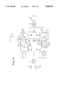
- FIG. 3 is a schematical diagram of a separation device according to a second embodiment of the present invention.
- FIG. 4 is a vertical cross-section view of an adsorption vessel for the separation device disclosed in FIGS. 2 and 3,
- FIG. 5 is a horizontal cross-section view of the vessel in FIG. 4, and
- FIG. 6 is a vertical cross-section view of a part of an enclosure panel provided in the vessel disclosed in FIGS. 4 and 5.
- the device comprises two vessels A and B, each enclosing a bed of adsorbent, such as molecular sieves particles.
- Each vessel A, B is provided with an inlet passage 1 and an outlet passage 2.
- the inlet passages 1 are connected to a pump 3 via conduit means 4 and to a vacuum pump 5 via conduit means 6.
- the outlet passages 2 are connected to a receiving means 7 via conduit means 8.
- a further conduit means 9 is provided between the outlet passages 2 of the vessels A and B.
- air is fed by means of the pump 3 to the bed of the vessel A through the inlet passage 1.
- a pressure equalization between the vessels A and B takes place by transferring oxygen enriched gases through the conduit means 9 and the respective outlet passages 2.
- a fourth, fifth and sixth step of operation corresponds to the first, second and third step of operation, respectively, except for the fact that the vessel B is supplied with air and the vessel A is regenerated.
- FIG. 2 discloses a separation device according to a first embodiment of the present invention.
- the device being a pressure swing adsorption apparatus, comprises a source means 10, a pump 11, a vessel A, a product gas receiving means 12, a vacuum pump 13, and a second, rest gas receiving means 14.
- the source means 10 may be in the form of a container or an inlet device, e.g. in the case of separation of air.
- the product gas receiving means 12 may be in the form of a container or a pipe means leading directly to a process using the gas produced by the separation device.
- the second, rest gas receiving means 14 may be in the form of a container or an outlet device leading to the ambient atmosphere.
- the vessel A is provided with a bed of adsorbing material, such as molecular sieves particles, e.g. in the form of zeolite, a first inlet/outlet passage 15A and a second inlet/outlet passage 16A.
- adsorbing material such as molecular sieves particles, e.g. in the form of zeolite
- the separation vessel A is symmetrical with respect to the passages and a midplane of the vessel and its bed.
- adsorbing material such as molecular sieves particles, e.g. in the form of zeolite
- the separation device comprises a conduit 17A', connecting the source means 10 to the first passage 15A of the vessel A, a conduit 18A", connecting the second passage 16A of the vessel A to the product gas receiving means 12, a conduit 17A", connecting the source means 10 to the second passage 16A of the vessel A, and a conduit 18A', connecting the first passage 15A of the vessel A to the product gas receiving means 12.
- a conduit 19A' connecting the first passage 15A of the vessel A to the second, rest gas receiving means 14, and a conduit 19A", connecting the second passage 16A of the vessel A to the second, rest gas receiving means 14.
- Each of the conduits 17A', 18A', 19A', 17A", 18A", and 19A" is provided with its respective valve means V.
- the source means 10 comprises a temperature regulating device 20 provided to maintain the gas temperature to the vessel A so that the adsorption process may take place under the optimal conditions.
- the adsorbing material of the vessel A is regenerated.
- the valve means V of the conduit 19A" is open and all other valve means V are closed, and the vacuum pump 13 will reduce the pressure in the vessel A and thereby evacuate a rest gas, containing essentially nitrogen and minor residual components, from the vessel A and discharge the rest gases to the second, rest gas receiving means or ambient air 14.
- air is fed by the pump 11 from the source means 10 via the conduit 17A" to the second passage 16A.
- the valve means V of the conduits 17A" and 18A' are open and the other valve means V are closed.
- the temperature of the air will be maintained at an optimal level.
- the air will be forced through the bed of the vessel A and the oxygen enriched gases produced will be forced out of the vessel A through the first passage 15A and via the conduit 18A' to the product receiving means 12.
- a fourth step of operation the adsorbing material of the vessel A is again regenerated.
- the valve means V of the conduit 19A" is open and all other valve means V are closed, and the vacuum pump 13 will reduce the pressure in the vessel A and thereby evacuate the rest gas from the vessel A and discharge it to the second, rest gas receiving means or ambient air 14.
- the process repeats the first to fourth steps of operation.
- FIG. 3 discloses a separation device according to a second embodiment of the present invention.
- the second embodiment refers to a pressure swing adsorption apparatus.
- This second embodiment differs from the first embodiment in that two separation vessels A and B have been provided. These two vessels A and B are essentially identical and have the same configuration as the vessel A in the first embodiment. Parts, such as the source means 10, the pump 11, the product receiving means 12, the vacuum pump 13, the second, rest gas receiving means 14, and the temperature regulating device 20 are essentially the same and therefore do not need to be explained again. Furthermore, it should be noted that elements of this second embodiment having the same function as corresponding elements in the first embodiment disclosed in FIG. 2 have the same reference signs.
- the vessel B comprises a first passage 15B and a second passage 16B, which correspond to the first and second passages 15A and 16A, respectively, of the vessel A.
- the vessel B is connected to the source means 10, the product receiving means 12 and the second, rest gas receiving means 14 by conduits 17B', 18B', 19B', 17B", 18B", and 19B", which correspond to the conduits 17A', 18A', 19A', 17A", 18A", and 19A", respectively, provided for the vessel A.
- the conduits 17A', 18A', 19A', 17A", 18A", and 19A" are provided with their respective valve means V.
- an inlet pipe 21 of the receiving means 12 is provided with valve 22.
- the vessel B is regenerated by evacuation of the rest gas through the first passage 15B.
- the valve means V of the conduits 18A" and 18B" are open as well as the valve 22 of the conduit 21, thereby permitting both oxygen purge from the vessel A to the vessel B via the second passages 16A and 16B as well as oxygen supply from the vessel A to the product gas receiving means 12.
- the valve 22 of the conduit 21 is then closed, thereby permitting pressure equalisation between the vessels A and B via the second passages 16A and 16B and the conduits 18A" and 18B".
- the valve means V of the conduit 17A" is closed and no air is supplied to the vessel A.
- the valve means V of the conduits 18A" and 18B' are open as well as the valve 22 of the conduit 21, thereby permitting both oxygen purge from the vessel B to the vessel A via the first passage 15B and the second passage 16A as well as oxygen supply from the vessel B to the product gas receiving means 12.
- the valve 22 of the conduit 21 is closed, thereby permitting pressure equalization between the vessels B and A via the first passage 15B and the second passage 16A and the conduits 18B' and 18A".
- the valve means of the conduit 17B" is closed and no air is supplied to vessel B.
- the vessel B is regenerated by evacuation of the rest gas through the second passage 16B.
- the valve means V of the conduits 18A' and 18B' are open as well as the valve 22 of the conduit 21, thereby permitting both oxygen purge from vessel A to vessel B via the first passages 15A and 15B as well as oxygen supply from the vessel A to the product gas receiving means 12.
- the valve 22 of the conduit 21 is closed, thereby permitting pressure equalization between the vessels A and B via the first passages 15A and 15B and the conduits 18A' and 18B'.
- the valve means V of the conduit 17A" is closed and no air is supplied to vessel A.
- the fourth step of operation comprising regeneration of the vessel A. as described above in connection with the first embodiment.
- air is supplied to the vessel B through the first passage 15B.
- the valve means V of the conduits 18A' and 18B" are open as well as the valve 22 of the conduit 21, thereby permitting both oxygen purge from the vessel B to the vessel A via the second passage 16B and the first passage 15A as well as oxygen supply from the vessel B to the product gas receiving means 12.
- the valve 22 of the conduit 21 is closed, thereby permitting pressure equalization between the vessels B and A via the second passage 16B and the first passage 15A and the conduits 18B" and 18A".
- the valve means V of the conduit 17B' is closed and thus no air is supplied to vessel B.
- the process repeats from the first to the fourth step of operation. Also in this second embodiment, the tendency to the development of a temperature gradient in the vessels A and B is effectively avoided. since the product end in the first and second steps of operation will be the feed end in the third and fourth steps of operation.
- FIGS. 4 and 5 disclose by way of example a vessel 31 to be used in the first or second embodiment described above.
- the vessel 31 has an elongated, essentially circular cylindrical wall around a vertical centre axis 32, an upper end wall 33 and a lower end wall (not shown), which is essentially spherically curved and forms the base of the vessel 31.
- a first passage 34 which may form the first passages 15A and 15B in the embodiments described above
- a second passage 35 which may form the second passages 16A and 16B in the embodiments described above and which is diametrically opposite to the first passage 34.
- An enclosure means 36 is provided in the vessel 31 to enclose an adsorbent 37 in the form of a bed of molecular sieve particles having a size of about 1-3 mm, such as zeolite.
- the enclosure means 36 is defined by a first and second enclosure panel 38 and 39, respectively, by the parts of the cylindrical wall of the vessel 31, which extend between said first and second enclosure panels 38, 39, by an upper end wall 40, and a lower end wall (not shown), which may be formed by said end wall of the vessel 31.
- the first and second enclosure panels 38, 39 are provided inside the first and second passage 34, 35, respectively, at a distance therefrom to provide a flow distribution space 41 therebetween and have an inner and outer surface extending parallel to the centre axis 32 along almost the total length of the vessel 31.
- the first and second enclosure panels 38, 39 are both perforated to permit fluid flow therethrough.
- Each enclosure panel 38, 39 is curved in one direction to a convex shape seen from the respective passage 34, 35.
- the curvature of each panet 38, 39 is such that it has an essentially circular cylindrical shape with a radius 42 of curvature being greater than the radius 43 of curvature of the cylindrical wall of the vessel 31.
- each enclosure panel 38, 39 has such a length that the distance between its lines of contact with the cylindrical wall corresponds to one side of a square inscribed in the cylindrical vessel 31, see FIG. 5. It should be noted that instead of the square shape a rectangle having two different side lengths may be inscribed in the cylindrical vessel 31.
- the relation between the radius 42 of the enclosure panel 38, 39 and the radius 43 of the cylindrical vessel wall should be greater than 1 and less than 5, preferably between 1.2 and 3, and more specifically between 1.5 and 2. This relation may lie outside these ranges if the square inscribed instead has the shape of a rectangle.
- the vessel 31 is symmetrically shaped with regard to a midplane 44. This means that both the first passage 34 and the second passage 35 may operate as an inlet passage and an outlet passage, respectively, during an adsorbing phase as well as during a regeneration phase.
- the perforations 45 of the enclosure panels 38, 39 are shaped as elongated slits being essentially perpendicular to the centre axis 32 and extending along the total width of each enclosure panel 38, 39.
- the perforations may be formed by means of elongated metal bars 46 provided in parallel with each other and with a gap 45 between each bar 46, see FIG. 6.
- the metal bars 46 are curved with a radius corresponding to the radius 42 of curvature. In cross-section each bar 46 is converging from the surface facing the particulate material 37 to the surface facing the flow distribution space 41.
- the smallest distance between each bar 46 is adjacent the inner surface facing the adsorbent 37. It is clear that this distance must be smaller than the size of the particles of the adsorbent 37.
- the bars 46 are supported and kept in proper position by means of elongated support means 47, in the form of a small beam, preferably welded to the bars 46.
- a closed space 48 Between the upper end wall 33 of the vessel 31 and the upper end wall 40 of the enclosure means 36, there is a provided a closed space 48.
- the upper end wall 40 of the enclosure means 36 comprises a flexible membrane.
- the closed space 48 is connected to a pressure regulating means 49, schematically disclosed. via conduit means 50.
- the pressure in the closed space 48 may be regulated such that the particulate material within the enclosure means 36 is maintained in a substantially motionless, fixed position. This means that as long as the pressure in the closed space 48 is higher than the pressure within the enclosure means 36, i.e.
- the flow rate of the gas may be increased in comparison with the prior art, since the particles of the bed 37 are hindered to move and start to fluidize due to said pressure difference. Moreover, since the particulate material 37 is immovable and since the vessel 31 is symmetrically shaped with regard to the midplane 44, high flow rates may be permitted in both the flow directions.
- the vessel 31 may function as described in the following example of separation of air.
- the air is introduced through the passage 34 and is distributed in the flow distribution space 41. From there the air is entering the bed 37 of adsorbent through the perforations in the convex enclosure panel 38.
- the air flows through the bed 37 such that the front of the gas flow is essentially plane when the flow passes the midplane 44. This means that the air is uniformly distributed to all parts of the bed 37 and all of the particles will be equally active in adsorbing nitrogen.
- the gas flow from which a substantial part of the nitrogen has been removed, is the leaving the vessel 31 via the other enclosure panel 39, the manifold space 41 and the passage 35.
- the process is reversed and the direction of the gas flow is changed, e.g. by means of a vacuum pump (not shown) connected to the passage 34. Due to the pressure decrease the nitrogen adsorbed will leave the bed 37 via the enclosure panel 38, the manifold space 41 and the passage 34.
- the present invention is not limited to the embodiment disclosed above but may be varied or modified within the scope of the following claims.
- the above description refers to the separation of air to produce oxygen, it should be clear to the person skilled in the art that the process and device according to the present invention also may be used for the production of other gases, for instance nitrogen, carbon dioxide, argon, etc.
- the process and device according to the present invention may be used for removing humidity, or other vapours, from air or other gases.
Landscapes
- Chemical & Material Sciences (AREA)
- Engineering & Computer Science (AREA)
- Analytical Chemistry (AREA)
- General Chemical & Material Sciences (AREA)
- Oil, Petroleum & Natural Gas (AREA)
- Chemical Kinetics & Catalysis (AREA)
- Separation Of Gases By Adsorption (AREA)
- Dairy Products (AREA)
- Treating Waste Gases (AREA)
Applications Claiming Priority (3)
| Application Number | Priority Date | Filing Date | Title |
|---|---|---|---|
| SE9600844A SE517561C2 (sv) | 1996-03-04 | 1996-03-04 | Förfarande och anordning för framställning av en gas genom separation från en gasblandning |
| SE9600844 | 1996-03-04 | ||
| PCT/SE1997/000332 WO1997032658A1 (en) | 1996-03-04 | 1997-02-26 | A process of and a device for producing a gas, containing at least one component, from a gas mixture |
Publications (1)
| Publication Number | Publication Date |
|---|---|
| US6068679A true US6068679A (en) | 2000-05-30 |
Family
ID=20401664
Family Applications (1)
| Application Number | Title | Priority Date | Filing Date |
|---|---|---|---|
| US09/142,297 Expired - Fee Related US6068679A (en) | 1996-03-04 | 1997-02-26 | Process of and a device for producing a gas, containing at least one component, from a gas mixture |
Country Status (8)
| Country | Link |
|---|---|
| US (1) | US6068679A (de) |
| EP (1) | EP0885051B1 (de) |
| AT (1) | ATE206954T1 (de) |
| DE (1) | DE69707427T2 (de) |
| DK (1) | DK0885051T3 (de) |
| ES (1) | ES2163131T3 (de) |
| SE (1) | SE517561C2 (de) |
| WO (1) | WO1997032658A1 (de) |
Cited By (24)
| Publication number | Priority date | Publication date | Assignee | Title |
|---|---|---|---|---|
| US7122073B1 (en) * | 2000-09-18 | 2006-10-17 | Praxair Technology, Inc. | Low void adsorption systems and uses thereof |
| US20090308759A1 (en) * | 2008-06-13 | 2009-12-17 | Marathon Gtf Technology, Ltd. | Bromine-based method and system for converting gaseous alkanes to liquid hydrocarbons using electrolysis for bromine recovery |
| US7674941B2 (en) | 2004-04-16 | 2010-03-09 | Marathon Gtf Technology, Ltd. | Processes for converting gaseous alkanes to liquid hydrocarbons |
| US7838708B2 (en) | 2001-06-20 | 2010-11-23 | Grt, Inc. | Hydrocarbon conversion process improvements |
| US7847139B2 (en) | 2003-07-15 | 2010-12-07 | Grt, Inc. | Hydrocarbon synthesis |
| US7880041B2 (en) | 2004-04-16 | 2011-02-01 | Marathon Gtf Technology, Ltd. | Process for converting gaseous alkanes to liquid hydrocarbons |
| US7883568B2 (en) | 2006-02-03 | 2011-02-08 | Grt, Inc. | Separation of light gases from halogens |
| US7964764B2 (en) | 2003-07-15 | 2011-06-21 | Grt, Inc. | Hydrocarbon synthesis |
| US7998438B2 (en) | 2007-05-24 | 2011-08-16 | Grt, Inc. | Zone reactor incorporating reversible hydrogen halide capture and release |
| US8008535B2 (en) | 2004-04-16 | 2011-08-30 | Marathon Gtf Technology, Ltd. | Process for converting gaseous alkanes to olefins and liquid hydrocarbons |
| US8053616B2 (en) | 2006-02-03 | 2011-11-08 | Grt, Inc. | Continuous process for converting natural gas to liquid hydrocarbons |
| US8173851B2 (en) | 2004-04-16 | 2012-05-08 | Marathon Gtf Technology, Ltd. | Processes for converting gaseous alkanes to liquid hydrocarbons |
| US8198495B2 (en) | 2010-03-02 | 2012-06-12 | Marathon Gtf Technology, Ltd. | Processes and systems for the staged synthesis of alkyl bromides |
| US8273929B2 (en) | 2008-07-18 | 2012-09-25 | Grt, Inc. | Continuous process for converting natural gas to liquid hydrocarbons |
| US8367884B2 (en) | 2010-03-02 | 2013-02-05 | Marathon Gtf Technology, Ltd. | Processes and systems for the staged synthesis of alkyl bromides |
| US8436220B2 (en) | 2011-06-10 | 2013-05-07 | Marathon Gtf Technology, Ltd. | Processes and systems for demethanization of brominated hydrocarbons |
| US8642822B2 (en) | 2004-04-16 | 2014-02-04 | Marathon Gtf Technology, Ltd. | Processes for converting gaseous alkanes to liquid hydrocarbons using microchannel reactor |
| US8802908B2 (en) | 2011-10-21 | 2014-08-12 | Marathon Gtf Technology, Ltd. | Processes and systems for separate, parallel methane and higher alkanes' bromination |
| US8815050B2 (en) | 2011-03-22 | 2014-08-26 | Marathon Gtf Technology, Ltd. | Processes and systems for drying liquid bromine |
| US8829256B2 (en) | 2011-06-30 | 2014-09-09 | Gtc Technology Us, Llc | Processes and systems for fractionation of brominated hydrocarbons in the conversion of natural gas to liquid hydrocarbons |
| US9193641B2 (en) | 2011-12-16 | 2015-11-24 | Gtc Technology Us, Llc | Processes and systems for conversion of alkyl bromides to higher molecular weight hydrocarbons in circulating catalyst reactor-regenerator systems |
| US9206093B2 (en) | 2004-04-16 | 2015-12-08 | Gtc Technology Us, Llc | Process for converting gaseous alkanes to liquid hydrocarbons |
| CN107438474A (zh) * | 2015-03-26 | 2017-12-05 | 乔治洛德方法研究和开发液化空气有限公司 | 用于通过包括四个吸附器的vpsa来生产氧气的方法 |
| US20220016568A1 (en) * | 2018-11-20 | 2022-01-20 | Gas Recovery And Recycle Limited | Gas recovery method |
Citations (28)
| Publication number | Priority date | Publication date | Assignee | Title |
|---|---|---|---|---|
| US2626675A (en) * | 1949-12-02 | 1953-01-27 | Nat Tank Co | Sorbing tower |
| US3740928A (en) * | 1971-05-25 | 1973-06-26 | Sulzer Ag | Apparatus for adsorbing carbon dioxide from air in a storage system |
| US3866428A (en) * | 1971-05-03 | 1975-02-18 | Air Liquide | Cryogenic separation of an air feed using multi-zone adsorption units |
| US4026680A (en) * | 1974-10-30 | 1977-05-31 | Union Carbide Corporation | Air separation by adsorption |
| US4336042A (en) * | 1980-10-14 | 1982-06-22 | Graham-White Sales Corporation | Canister-compactor assembly |
| US4354859A (en) * | 1981-08-06 | 1982-10-19 | Union Carbide Corporation | Enhanced gas separation by selective adsorption |
| US4448592A (en) * | 1981-08-18 | 1984-05-15 | Linde Ag | Adsorptive method for the separation of a gas mixture |
| SE438266B (sv) * | 1977-10-18 | 1985-04-15 | Linde Ag | Anordning for adsorptiv rening av gaser |
| US5071449A (en) * | 1990-11-19 | 1991-12-10 | Air Products And Chemicals, Inc. | Gas separation by rapid pressure swing adsorption |
| US5133784A (en) * | 1990-10-11 | 1992-07-28 | L'air Liquide, Societe Anonyme Pour L'etude Et L'exploitation Des Procedes Georges Claude | Process and apparatus for separating a at least a component of a gaseous mixture by adsorption |
| US5169413A (en) * | 1991-10-07 | 1992-12-08 | Praxair Technology Inc. | Low temperature pressure swing adsorption with refrigeration |
| US5176721A (en) * | 1990-10-11 | 1993-01-05 | L'air Liquide, Societe Anonyme Pour L'etude Et L'exploitation Des Procedes Georges Claude | Adsorber and process for the separation by adsorption |
| US5268022A (en) * | 1991-03-07 | 1993-12-07 | The Boc Group Plc | Gas separation method and apparatus |
| JPH06154537A (ja) * | 1992-11-24 | 1994-06-03 | Sanden Corp | ガス処理装置 |
| US5407465A (en) * | 1993-12-16 | 1995-04-18 | Praxair Technology, Inc. | Tuning of vacuum pressure swing adsorption systems |
| US5441559A (en) * | 1992-04-13 | 1995-08-15 | L'air Liquide, Societe Anonyme Pour L'etude Et L'exploitation Des Procedes Georges Claude | Rotatable device for the separation by adsorption of at least one constituent of a gaseous mixture |
| US5447558A (en) * | 1993-02-25 | 1995-09-05 | The Boc Group Plc | Purification method and apparatus |
| WO1996004978A1 (en) * | 1994-08-12 | 1996-02-22 | The Dow Chemical Company | Pressure swing adsorption apparatus and process for recovery of organic vapors |
| US5520720A (en) * | 1994-11-30 | 1996-05-28 | The Boc Group, Inc. | Pressure swing adsorption process |
| US5520721A (en) * | 1993-01-08 | 1996-05-28 | L'air Liquide, Societe Anonyme Pour L'etude Et L'exploitation Des Procedes Georges Claude | Adsorption process and unit for the production of a gas by separation of a gaseous mixture |
| US5593475A (en) * | 1995-04-13 | 1997-01-14 | Liquid Air Engineering Corporation | Mixed bed adsorber |
| US5624477A (en) * | 1991-05-09 | 1997-04-29 | The Boc Group Plc | Pressure swing adsorption plants |
| US5632804A (en) * | 1992-08-18 | 1997-05-27 | Jacques Ribesse | Process and apparatus for separating constituents of a gas mixture by adsorption |
| US5632807A (en) * | 1993-06-03 | 1997-05-27 | L'air Liquide, Societe Anonyme Pour L'etude Et L'exploitation Des Procedes Georges Claude | Device for the separation of elements of a gas mixture by adsorption |
| US5656068A (en) * | 1996-02-29 | 1997-08-12 | Praxair Technology, Inc. | Large capacity vacuum pressure swing adsorption process and system |
| US5672196A (en) * | 1995-08-01 | 1997-09-30 | The Boc Group, Inc. | Process and apparatus for the separation of gases |
| US5674311A (en) * | 1995-10-20 | 1997-10-07 | Praxair Technology, Inc. | Adsorption process and system using multilayer adsorbent beds |
| US5759242A (en) * | 1996-07-23 | 1998-06-02 | Praxair Technology, Inc. | Radial bed vaccum/pressure swing adsorber vessel |
-
1996
- 1996-03-04 SE SE9600844A patent/SE517561C2/sv not_active IP Right Cessation
-
1997
- 1997-02-26 DK DK97907506T patent/DK0885051T3/da active
- 1997-02-26 AT AT97907506T patent/ATE206954T1/de not_active IP Right Cessation
- 1997-02-26 WO PCT/SE1997/000332 patent/WO1997032658A1/en not_active Ceased
- 1997-02-26 DE DE69707427T patent/DE69707427T2/de not_active Expired - Fee Related
- 1997-02-26 ES ES97907506T patent/ES2163131T3/es not_active Expired - Lifetime
- 1997-02-26 US US09/142,297 patent/US6068679A/en not_active Expired - Fee Related
- 1997-02-26 EP EP97907506A patent/EP0885051B1/de not_active Expired - Lifetime
Patent Citations (29)
| Publication number | Priority date | Publication date | Assignee | Title |
|---|---|---|---|---|
| US2626675A (en) * | 1949-12-02 | 1953-01-27 | Nat Tank Co | Sorbing tower |
| US3866428A (en) * | 1971-05-03 | 1975-02-18 | Air Liquide | Cryogenic separation of an air feed using multi-zone adsorption units |
| US3740928A (en) * | 1971-05-25 | 1973-06-26 | Sulzer Ag | Apparatus for adsorbing carbon dioxide from air in a storage system |
| US4026680A (en) * | 1974-10-30 | 1977-05-31 | Union Carbide Corporation | Air separation by adsorption |
| SE438266B (sv) * | 1977-10-18 | 1985-04-15 | Linde Ag | Anordning for adsorptiv rening av gaser |
| US4336042A (en) * | 1980-10-14 | 1982-06-22 | Graham-White Sales Corporation | Canister-compactor assembly |
| US4354859A (en) * | 1981-08-06 | 1982-10-19 | Union Carbide Corporation | Enhanced gas separation by selective adsorption |
| US4448592A (en) * | 1981-08-18 | 1984-05-15 | Linde Ag | Adsorptive method for the separation of a gas mixture |
| EP0612553A2 (de) * | 1990-10-11 | 1994-08-31 | L'air Liquide, Societe Anonyme Pour L'etude Et L'exploitation Des Procedes Georges Claude | Adsorptionsvorrichtung zur Trennung einer Gasmischung |
| US5176721A (en) * | 1990-10-11 | 1993-01-05 | L'air Liquide, Societe Anonyme Pour L'etude Et L'exploitation Des Procedes Georges Claude | Adsorber and process for the separation by adsorption |
| US5133784A (en) * | 1990-10-11 | 1992-07-28 | L'air Liquide, Societe Anonyme Pour L'etude Et L'exploitation Des Procedes Georges Claude | Process and apparatus for separating a at least a component of a gaseous mixture by adsorption |
| US5071449A (en) * | 1990-11-19 | 1991-12-10 | Air Products And Chemicals, Inc. | Gas separation by rapid pressure swing adsorption |
| US5268022A (en) * | 1991-03-07 | 1993-12-07 | The Boc Group Plc | Gas separation method and apparatus |
| US5624477A (en) * | 1991-05-09 | 1997-04-29 | The Boc Group Plc | Pressure swing adsorption plants |
| US5169413A (en) * | 1991-10-07 | 1992-12-08 | Praxair Technology Inc. | Low temperature pressure swing adsorption with refrigeration |
| US5441559A (en) * | 1992-04-13 | 1995-08-15 | L'air Liquide, Societe Anonyme Pour L'etude Et L'exploitation Des Procedes Georges Claude | Rotatable device for the separation by adsorption of at least one constituent of a gaseous mixture |
| US5632804A (en) * | 1992-08-18 | 1997-05-27 | Jacques Ribesse | Process and apparatus for separating constituents of a gas mixture by adsorption |
| JPH06154537A (ja) * | 1992-11-24 | 1994-06-03 | Sanden Corp | ガス処理装置 |
| US5520721A (en) * | 1993-01-08 | 1996-05-28 | L'air Liquide, Societe Anonyme Pour L'etude Et L'exploitation Des Procedes Georges Claude | Adsorption process and unit for the production of a gas by separation of a gaseous mixture |
| US5447558A (en) * | 1993-02-25 | 1995-09-05 | The Boc Group Plc | Purification method and apparatus |
| US5632807A (en) * | 1993-06-03 | 1997-05-27 | L'air Liquide, Societe Anonyme Pour L'etude Et L'exploitation Des Procedes Georges Claude | Device for the separation of elements of a gas mixture by adsorption |
| US5407465A (en) * | 1993-12-16 | 1995-04-18 | Praxair Technology, Inc. | Tuning of vacuum pressure swing adsorption systems |
| WO1996004978A1 (en) * | 1994-08-12 | 1996-02-22 | The Dow Chemical Company | Pressure swing adsorption apparatus and process for recovery of organic vapors |
| US5520720A (en) * | 1994-11-30 | 1996-05-28 | The Boc Group, Inc. | Pressure swing adsorption process |
| US5593475A (en) * | 1995-04-13 | 1997-01-14 | Liquid Air Engineering Corporation | Mixed bed adsorber |
| US5672196A (en) * | 1995-08-01 | 1997-09-30 | The Boc Group, Inc. | Process and apparatus for the separation of gases |
| US5674311A (en) * | 1995-10-20 | 1997-10-07 | Praxair Technology, Inc. | Adsorption process and system using multilayer adsorbent beds |
| US5656068A (en) * | 1996-02-29 | 1997-08-12 | Praxair Technology, Inc. | Large capacity vacuum pressure swing adsorption process and system |
| US5759242A (en) * | 1996-07-23 | 1998-06-02 | Praxair Technology, Inc. | Radial bed vaccum/pressure swing adsorber vessel |
Cited By (32)
| Publication number | Priority date | Publication date | Assignee | Title |
|---|---|---|---|---|
| US7122073B1 (en) * | 2000-09-18 | 2006-10-17 | Praxair Technology, Inc. | Low void adsorption systems and uses thereof |
| US8415512B2 (en) | 2001-06-20 | 2013-04-09 | Grt, Inc. | Hydrocarbon conversion process improvements |
| US7838708B2 (en) | 2001-06-20 | 2010-11-23 | Grt, Inc. | Hydrocarbon conversion process improvements |
| US7964764B2 (en) | 2003-07-15 | 2011-06-21 | Grt, Inc. | Hydrocarbon synthesis |
| US7847139B2 (en) | 2003-07-15 | 2010-12-07 | Grt, Inc. | Hydrocarbon synthesis |
| US8008535B2 (en) | 2004-04-16 | 2011-08-30 | Marathon Gtf Technology, Ltd. | Process for converting gaseous alkanes to olefins and liquid hydrocarbons |
| US7880041B2 (en) | 2004-04-16 | 2011-02-01 | Marathon Gtf Technology, Ltd. | Process for converting gaseous alkanes to liquid hydrocarbons |
| US7674941B2 (en) | 2004-04-16 | 2010-03-09 | Marathon Gtf Technology, Ltd. | Processes for converting gaseous alkanes to liquid hydrocarbons |
| US9206093B2 (en) | 2004-04-16 | 2015-12-08 | Gtc Technology Us, Llc | Process for converting gaseous alkanes to liquid hydrocarbons |
| US8173851B2 (en) | 2004-04-16 | 2012-05-08 | Marathon Gtf Technology, Ltd. | Processes for converting gaseous alkanes to liquid hydrocarbons |
| US8232441B2 (en) | 2004-04-16 | 2012-07-31 | Marathon Gtf Technology, Ltd. | Process for converting gaseous alkanes to liquid hydrocarbons |
| US8642822B2 (en) | 2004-04-16 | 2014-02-04 | Marathon Gtf Technology, Ltd. | Processes for converting gaseous alkanes to liquid hydrocarbons using microchannel reactor |
| US7883568B2 (en) | 2006-02-03 | 2011-02-08 | Grt, Inc. | Separation of light gases from halogens |
| US8053616B2 (en) | 2006-02-03 | 2011-11-08 | Grt, Inc. | Continuous process for converting natural gas to liquid hydrocarbons |
| US8921625B2 (en) | 2007-02-05 | 2014-12-30 | Reaction35, LLC | Continuous process for converting natural gas to liquid hydrocarbons |
| US7998438B2 (en) | 2007-05-24 | 2011-08-16 | Grt, Inc. | Zone reactor incorporating reversible hydrogen halide capture and release |
| US8282810B2 (en) | 2008-06-13 | 2012-10-09 | Marathon Gtf Technology, Ltd. | Bromine-based method and system for converting gaseous alkanes to liquid hydrocarbons using electrolysis for bromine recovery |
| US20090308759A1 (en) * | 2008-06-13 | 2009-12-17 | Marathon Gtf Technology, Ltd. | Bromine-based method and system for converting gaseous alkanes to liquid hydrocarbons using electrolysis for bromine recovery |
| US8273929B2 (en) | 2008-07-18 | 2012-09-25 | Grt, Inc. | Continuous process for converting natural gas to liquid hydrocarbons |
| US8415517B2 (en) | 2008-07-18 | 2013-04-09 | Grt, Inc. | Continuous process for converting natural gas to liquid hydrocarbons |
| US8198495B2 (en) | 2010-03-02 | 2012-06-12 | Marathon Gtf Technology, Ltd. | Processes and systems for the staged synthesis of alkyl bromides |
| US8367884B2 (en) | 2010-03-02 | 2013-02-05 | Marathon Gtf Technology, Ltd. | Processes and systems for the staged synthesis of alkyl bromides |
| US9133078B2 (en) | 2010-03-02 | 2015-09-15 | Gtc Technology Us, Llc | Processes and systems for the staged synthesis of alkyl bromides |
| US8815050B2 (en) | 2011-03-22 | 2014-08-26 | Marathon Gtf Technology, Ltd. | Processes and systems for drying liquid bromine |
| US8436220B2 (en) | 2011-06-10 | 2013-05-07 | Marathon Gtf Technology, Ltd. | Processes and systems for demethanization of brominated hydrocarbons |
| US8829256B2 (en) | 2011-06-30 | 2014-09-09 | Gtc Technology Us, Llc | Processes and systems for fractionation of brominated hydrocarbons in the conversion of natural gas to liquid hydrocarbons |
| US8802908B2 (en) | 2011-10-21 | 2014-08-12 | Marathon Gtf Technology, Ltd. | Processes and systems for separate, parallel methane and higher alkanes' bromination |
| US9193641B2 (en) | 2011-12-16 | 2015-11-24 | Gtc Technology Us, Llc | Processes and systems for conversion of alkyl bromides to higher molecular weight hydrocarbons in circulating catalyst reactor-regenerator systems |
| CN107438474A (zh) * | 2015-03-26 | 2017-12-05 | 乔治洛德方法研究和开发液化空气有限公司 | 用于通过包括四个吸附器的vpsa来生产氧气的方法 |
| CN107438474B (zh) * | 2015-03-26 | 2020-06-02 | 乔治洛德方法研究和开发液化空气有限公司 | 用于通过包括四个吸附器的vpsa来生产氧气的方法 |
| US20220016568A1 (en) * | 2018-11-20 | 2022-01-20 | Gas Recovery And Recycle Limited | Gas recovery method |
| US12201936B2 (en) * | 2018-11-20 | 2025-01-21 | Gas Recovery And Recycle Limited | Gas recovery method |
Also Published As
| Publication number | Publication date |
|---|---|
| DE69707427T2 (de) | 2002-06-20 |
| DK0885051T3 (da) | 2001-12-03 |
| SE9600844D0 (sv) | 1996-03-04 |
| EP0885051A1 (de) | 1998-12-23 |
| SE9600844L (sv) | 1997-09-05 |
| WO1997032658A1 (en) | 1997-09-12 |
| EP0885051B1 (de) | 2001-10-17 |
| DE69707427D1 (de) | 2001-11-22 |
| ES2163131T3 (es) | 2002-01-16 |
| SE517561C2 (sv) | 2002-06-18 |
| ATE206954T1 (de) | 2001-11-15 |
Similar Documents
| Publication | Publication Date | Title |
|---|---|---|
| US6068679A (en) | Process of and a device for producing a gas, containing at least one component, from a gas mixture | |
| EP1880753B2 (de) | Druckwechseladsorptionsverfahren und -system mit Lagerungen mit mehreren Behältern | |
| KR101140541B1 (ko) | Psa 흐름 변화의 향상된 제어를 위한 방법 및 장치 | |
| EP0681859B1 (de) | Vakuum-Wechsel-Adsorption mit gemischtem Druckaufbau | |
| EP0750934B1 (de) | Vakuum-Wechsel-Adsorptionsverfahren | |
| CN105339071B (zh) | 吸附床结构及过程 | |
| EP0873776B1 (de) | Druckwechseladsorptionsverfahren | |
| US5772737A (en) | Process for treating a gas mixture by pressure swing adsorption | |
| US6789400B2 (en) | Cap assembly and optical fiber cooling process | |
| JPH1190156A (ja) | 圧力スイング吸着により気体混合物を分離するための装置および方法 | |
| US5090973A (en) | Psa employing high purity purging | |
| EP0885050B1 (de) | Zylindrisches gefäss zur trennung | |
| JPS58151304A (ja) | プレツシヤ−スイング法による酸素製造方法 | |
| JPH11512971A (ja) | 圧力スイング吸着による気体混合物の処理のための方法およびプラント | |
| JP7195887B2 (ja) | 圧力変動吸着装置 | |
| JPH04293513A (ja) | 圧力変動吸着法による富酸素ガスの製造方法 | |
| JP2001327829A (ja) | 圧力スイング吸着装置 | |
| JPH0739919U (ja) | 混合ガスの分離装置 | |
| JPS58143820A (ja) | 吸着装置 | |
| JPH0494718A (ja) | 混合ガスから特定成分ガスを分離する方法及びそれに用いる装置 | |
| JPH09141036A (ja) | ガス分離供給装置 | |
| JPH057718A (ja) | 圧力スイング式ガス分離装置 |
Legal Events
| Date | Code | Title | Description |
|---|---|---|---|
| AS | Assignment |
Owner name: AGA AKTIEBOLAG, SWEDEN Free format text: ASSIGNMENT OF ASSIGNORS INTEREST;ASSIGNOR:ZHENG, GUHONG;REEL/FRAME:009492/0622 Effective date: 19980910 |
|
| FEPP | Fee payment procedure |
Free format text: PAYOR NUMBER ASSIGNED (ORIGINAL EVENT CODE: ASPN); ENTITY STATUS OF PATENT OWNER: LARGE ENTITY |
|
| CC | Certificate of correction | ||
| FPAY | Fee payment |
Year of fee payment: 4 |
|
| REMI | Maintenance fee reminder mailed | ||
| LAPS | Lapse for failure to pay maintenance fees | ||
| STCH | Information on status: patent discontinuation |
Free format text: PATENT EXPIRED DUE TO NONPAYMENT OF MAINTENANCE FEES UNDER 37 CFR 1.362 |
|
| FP | Lapsed due to failure to pay maintenance fee |
Effective date: 20080530 |