US6072658A - Cassette mounting device having link mechanism arranged to support cassette holder - Google Patents
Cassette mounting device having link mechanism arranged to support cassette holder Download PDFInfo
- Publication number
- US6072658A US6072658A US08/615,675 US61567596A US6072658A US 6072658 A US6072658 A US 6072658A US 61567596 A US61567596 A US 61567596A US 6072658 A US6072658 A US 6072658A
- Authority
- US
- United States
- Prior art keywords
- chassis
- holder
- cassette
- lever
- levers
- Prior art date
- Legal status (The legal status is an assumption and is not a legal conclusion. Google has not performed a legal analysis and makes no representation as to the accuracy of the status listed.)
- Expired - Fee Related
Links
- 230000007246 mechanism Effects 0.000 title claims description 30
- 239000000463 material Substances 0.000 claims description 5
- CWYNVVGOOAEACU-UHFFFAOYSA-N Fe2+ Chemical compound [Fe+2] CWYNVVGOOAEACU-UHFFFAOYSA-N 0.000 claims description 3
- 229910052782 aluminium Inorganic materials 0.000 claims description 3
- XAGFODPZIPBFFR-UHFFFAOYSA-N aluminium Chemical compound [Al] XAGFODPZIPBFFR-UHFFFAOYSA-N 0.000 claims description 3
- 230000009467 reduction Effects 0.000 description 10
- 230000009471 action Effects 0.000 description 7
- 230000007423 decrease Effects 0.000 description 1
- 238000003780 insertion Methods 0.000 description 1
- 230000037431 insertion Effects 0.000 description 1
- 238000003754 machining Methods 0.000 description 1
- 230000007257 malfunction Effects 0.000 description 1
- 238000005259 measurement Methods 0.000 description 1
- 239000007769 metal material Substances 0.000 description 1
- 238000012986 modification Methods 0.000 description 1
- 230000004048 modification Effects 0.000 description 1
- 230000004044 response Effects 0.000 description 1
Images



Classifications
-
- G—PHYSICS
- G11—INFORMATION STORAGE
- G11B—INFORMATION STORAGE BASED ON RELATIVE MOVEMENT BETWEEN RECORD CARRIER AND TRANSDUCER
- G11B15/00—Driving, starting or stopping record carriers of filamentary or web form; Driving both such record carriers and heads; Guiding such record carriers or containers therefor; Control thereof; Control of operating function
- G11B15/675—Guiding containers, e.g. loading, ejecting cassettes
- G11B15/67544—Guiding containers, e.g. loading, ejecting cassettes with movement of the cassette parallel to its main side and subsequent movement perpendicular thereto, i.e. front loading
- G11B15/67555—Guiding containers, e.g. loading, ejecting cassettes with movement of the cassette parallel to its main side and subsequent movement perpendicular thereto, i.e. front loading the second movement only being made by the cassette holder
- G11B15/67557—Guiding containers, e.g. loading, ejecting cassettes with movement of the cassette parallel to its main side and subsequent movement perpendicular thereto, i.e. front loading the second movement only being made by the cassette holder with servo control
Definitions
- This invention relates to a cassette mounting device for mounting and demounting a cassette on and from the body of a recording and/or reproducing apparatus such as a VTR by moving a cassette holder up and down, and also relates to a recording and/or reproducing apparatus provided with such a cassette mounting device.
- Cassette mounting devices which have heretofore been arranged to mount and demount a tape cassette on and from the body of, say, an 8 mm VTR or the like car be divided into two types.
- One is an automatic loading (or front loading) type which is arranged to be used for an installed type VTR and which is provided with a drive source.
- the other is a pop-up type which is arranged to be used for a camera-integrated type VTR and to be rendered operative when a cassette holder is pushed down by the operator of the VTR.
- the simplification of mechanism and the reduction in weight thereof have advanced according to the recent trend of the reduction in size of the camera-integrated type VTR or the like and, as a result, the cassette mounting device has come to be usually arranged to have a lock mechanism for locking the cassette holder in its lowered position only on one side of the cassette holder.
- This arrangement is called a single-side(d lock type.
- the single-sided lock type cassette mounting device has an arrangement in which the pushing-down force is applied to the cassette holder directly by the operator, the reduction in size and weight has come to cause difficulty in arranging t-he cassette mounting device to adequately keep its function and strength and to give an adequate feeling of operation thereon.
- FIGS. 6(a) and 6(b) to FIGS. 9(a) and 9(b) show the conventional cassette mounting device.
- FIG. 6(a) shows the cassette holder in its raised (popped-up) state.
- FIG. 6(b) shows the cassette holder in its lowered (locked) state.
- FIG. 7 is a top view of the whole cassette mounting device. The conventional cassette mounting device is described below with reference to those figures.
- the illustrations include a tape cassette 1, a magnetic tape 2 contained within the tape cassette 1, and a main chassis 3 of a VTR body.
- a rotary drum 4 which has a plurality of recording/reproducing heads is disposed on the main chassis 3.
- a sliding chassis 5 is arranged to be slidable over the main chassis 3.
- a cassette holder 6 is arranged to allow the tape cassette 1 to be inserted therein.
- First and second levers 7 and 8 form X-shaped links on both sides of the cassette holder 6.
- a fulcrum shaft 9 is arranged in each of the X-shaped links to rotatably connect the first and second levers 7 and 8 to each other.
- a connection shaft 10 is arranged to interconnect one ends of the first levers 7 dispose(d on both sides of the cassette holder 6 for synchronizing the phases of the X-shaped links on the two sides and also serves to swingably support the first levers 7 on the cassette holder 6.
- a shaft pin 11 is disposed at the other end of each of the first levers 7.
- a cam slot 12 is formed in each of the side plates of the sliding chassis 5. The shaft pin 11 is engaging the cam slot 12.
- a shaft pin 13 is disposed at one end of each of the second levers 8 and is rotatably supported by each corresponding side plate of the sliding chassis 5.
- a cam slot 14 is formed in the other end of each of the second levers 8.
- a shaft pin 15 is arranged on each side plate of the cassette holder 6 to slidably engage the cam slot 14.
- a tension spring 16 stretches between each pair of the first and second levers 7 and 8 to exert an urging force for moving the cassette holder 6 up.
- Cassette retaining springs 17 are provided on the upper surface of the cassette holder 6.
- Reel mounts 19 are disposed on the sliding chassis 5.
- the cassette holder 6 When the cassette holder 6 is pushed down against the force of the springs 16 after insertion of the tape cassette 1 into the cassette holder 6 in the popped-up state as shown in FIG. 6(a), the cassette holder 6 comes to its lowered position, as shown in FIG. 6(b), where the cassette holder 6 is locked and kept in the locked state by a lock mechanism 20, which is disposed on the side opposite to the illustrated side.
- the lid 1a of the tape cassette 1 is opened by the lid opener 18 while the cassette holder 6 is being moved down.
- the tape cassette 1 With the cassette holder 6 in the locked state, the tape cassette 1 is mounted on the reel mounts 19 of the sliding chassis 5, while the cassette retaining springs 17 push the tape cassette 1 from above.
- the sliding chassis 5 is slid in the direction of approaching the rotary drum 4 and, at the same time, the tape 2 is pulled out from the tape cassette 1 by means of a loading mechanism which is not shown.
- a loading mechanism which is not shown.
- at least a part of the rotary drum 4 is relatively inserted into an opening part of the cassette 1 in such a way as to have a portion of the tape 2 wrapped around the circumferential surface of the rotary drum 4.
- the tape 2 is then allowed to travel and signals are recorded or reproduced by the recording/reproducing heads of the rotary drum 4.
- the operation is performed in the order reverse to the above-stated operation.
- the sliding chassis 5 is slid in the direction of going away from the rotary drum 4, the tape 2 is rewound up into the tape cassette 1.
- the cassette holder 6 is unlocked by an eject mechanism which is not shown.
- the X-shaped links are operated by the force of the springs 16 to move up the cassette holder 6 into the popped-up position as shown in
- the lock mechanism 20 is generally provided only on one side of the cassette holder 6, as mentioned above, for the purpose of reduction in size and weight of the cassette mounting device.
- a positioning action on the side opposite to the locking side is carried out by causing the first and second levers 7 and 8 on this side to follow the phases of the first and second levers 7 and 8 disposed on the locking side, by means of the rigidity of the connection shaft 10 and the cassette holder 6.
- FIG. 8 shows, in an oblique view, how this positioning action of the link mechanism is carried out, in a simplified manner, omitting the cassette holder 6 from the drawing.
- the X-shaped link (the first and second levers 7 and 8) on the side opposite to the locking side is arranged to receive a lifting force which is a resultant force resulting from the lifting force of the springs 16, a reaction force caused by the cassette retaining springs 17 and a reaction force caused by a lid closing spring of the lid 1a of the tape cassette 1, and to suppress the resultant force mainly by the rigidity of the connection shaft 10.
- FIGS. 9(a) and 9(b) are side views showing how a force is exerted on the side opposite to the locking side.
- the link mechanism and parts therearound are shown in a simplified manner to facilitate understanding.
- FIG. 9(a) shows the popped-up state
- FIG. 9(b) shows the locked state of the cassette holder 6.
- the cassette holding action on the side opposite to the lock mechanism 20 is performed, as mentioned above, through the connection of the right and left links made, as mentioned above, mainly by the connection shaft 10 and the first levers 7.
- a torque for closing the link as shown by an arrow T acts on the first lever 7 disposed on the side opposite to the lock mechanism 20.
- the torque T is balanced with the above-stated lifting force for the cassette holder 6, so that the cassette holder 6, i.e., the tape cassette 1, can be held in a correct position.
- the link mechanism of the conventional cassette mounting device which is arranged in the above-stated manner is generally configured in the form of X link.
- the first and second levers 7 and 8 which jointly form each X-shaped link are rotatably connected approximately in the middle part of the X-shaped link by means of the fulcrum shaft 9.
- Each of the levers 7 and 8 is arranged to swing on the connection shaft 10 or the shaft pin 13 at its one end and to make the shaft pin 11 or 15 slidably engage the cam slot 12 or 14 at the other end.
- the cam slot 12 which is one of a pair of cam slots is formed in a mounting chassis, i.e., the sliding chassis 5, while the other cam slot 14 is formed in the second lever 8.
- the cam slot 12 is either formed aslant, as in the case of this example, to cause the shaft pin 11 to move also downward accordingly as the cassette holder 6 is moved down, or formed in parallel to the horizontal surface of the sliding chassis 5.
- the component force Fx is exerted in the direction of moving the cassette holder 6 upward (as shown by an arrow u in the drawing) and thus decreases the torque T applied for holding the cassette holder 6.
- the direction of the reaction force F is disadvantageous in a case where some external force happens to exert a lifting force on the cassette holder 6. This results in a weaker holding force. Therefore, in order to accurately hold the tape cassette 1, it is necessary to increase the phase difference "h" of the first lever 7.
- the pushing-down force on the cassette holder 6 easily causes the first lever 7 to swing counterclockwise and the shaft pin 11 to move downward within the cam slot 12 in the direction of arrow d, so that the first lever 7 swings in the direction of closing the link. Therefore, there is only a weak resistance to the downward pushing force on the cassette holder 6.
- the feeling of a tape cassette mounting operation varies with the individual operator.
- such a weak resistance tends to give a keeling of lack of rigidity (as the cassette holder 6 moves up and down too readily in response to a slight pushing force) to impair the touch of high-quality and reliability of the device.
- a cassette mounting device comprises a chassis, a holder for holding a cassette, a pair of link mechanisms disposed respectively on two opposite sides of the holder and arranged to connect the holder to the chassis, each of the pair of link mechanisms having a first lever and a second lever which are interconnected in an X-like shape to be respectively swingable about a connection point at which the first lever and the second lever are interconnected, and a connection member arranged to connect the first levers of the pair of link mechanisms to each other at respective first end parts of the first levers, wherein each of the first levers has the first end part swingably connected to the holder and has a second end part arranged to engage the chassis in such a way as to be movable over the chassis in a direction of approaching the holder according to an approaching operation of the holder toward the chassis, and wherein each of the second levers has one end part swingably connected to the chassis.
- a recording and/or reproducing apparatus comprises a first chassis on which a head for recording and/or reproduction is disposed, a second chassis arranged to be movable relative to the first chassis, a holder for holding a cassette, a pair of link mechanisms disposed respectively on two opposite sides of the holder and arranged to connect the holder to the second chassis, each of the pair of link mechanisms having a first lever and a second lever which are interconnected in an X-like shape to be respectively swingable about a connection point at which the first lever and the second lever are interconnected, and a connection member arranged to connect the first levers of the pair of link mechanisms to each other at respective first end parts of the first levers, wherein each of the first levers has the first end part swingably connected to the holder and has a second end part arranged to engage the second chassis in such a way as to be movable over the second chassis in a direction of approaching the holder according to an approaching operation of the holder
- FIGS. 1(a) and 1(b) are side views showing the whole cassette mounting device of a first embodiment of this invention.
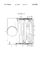
- FIG. 2 is a top view showing the whole cassette mounting device of the first embodiment.
- FIGS. 3(a) and 3(b) are side views showing essential parts of the first embodiment and how forces are exerted in the first embodiment.
- FIGS. 4(a) and 4(b) are side views showing essential parts of a second embodiment of this invention.
- FIGS. 5(a) and 5(b) are side views showing essential parts of a third embodiment of this invention.
- FIGS. 6(a) and 6(b) are side views showing the conventional device in its entirety.
- FIG. 7 is a top view showing the conventional device in its entirety.
- FIG. 8 is an exploded oblique view showing essential parts of the conventional device.
- FIGS. 9(a) and 9(b) are side views showing essential parts of the conventional device and how forces are exerted in the conventional device.
- FIGS. 1(a) and 1(b) to FIGS. 3(a) and 3(b) show a first embodiment of this invention.
- FIGS. 1(a) and 1(b) are side views of the whole cassette mounting device of the first embodiment showing one side opposite to a locking side of the cassette mounting device.
- the cassette mounting device is shown as in a popped-up state in FIG. 1(a) and as in a locked state in FIG. 1(b).
- FIG. 2 is a top view of the whole cassette mounting device.
- FIGS. 3(a) and 3(b) are side views taken from the one side opposite to the locking side to show how forces are exerted on the link mechanism.
- the cassette mounting device is shown as in the popped-up state in FIG. 3(a) and as in the locked state in FIG. 3(b).
- a tape cassette 1 is inserted into a cassette holder 6 in the direction of an arrow.
- the cassette holder 6 is then pushed down to the position of FIG. 1(b), where the cassette holder 6 is locked by a lock mechanism 20 which is disposed on the side opposite to the side shown.
- the basic action and actions to be performed thereafter as a VTR are the same as in the case of the conventional device. All the parts of the embodiment that are arranged in substantially the same manner as those of the conventional device are indicated by the same reference numerals as those used in the foregoing description of the prior art, and details of them are omitted from the following description.
- connection shaft 10 which serves to adjust the phases of the links on right and left sides of the cassette holder 6 to each other is disposed, unlike the conventional device, in a position near to the cassette inserting opening, for the purpose of more effectively giving the feeling of rigidity, because a load of pushing down the cassette holder 6 is mainly located near the cassette inserting opening.
- other points of the basic: arrangement of this embodiment are the same as those of the conventional device described.
- a feature of this embodiment lies in that, unlike the conventional device, the form of a cam slot 30 provided in each of the side plates of the sliding chassis 5 has such an inclination as to cause the shaft pin 11 of the first lever 7 to move upward according to the descent of the cassette holder 6.
- the inclination of the cam slot 30 may be set at least at a part 30a which corresponds to the raised position of the cassette holder 6 and at a part 30b which corresponds to the lowered position of the cassette holder 6.
- the cam slot 30 is formed in a linear shape at a predetermined angle of inclination. The advantageous action of the cam slot 30 is described below with reference to FIGS. 3(a) and 3(b).
- the component Fx is made to act in a direction reverse to the direction (indicated by an arrow "u") in which the shaft pin 11 moves when the cassette holder 6 ascends.
- the phase difference imparted to the first lever 7 is allowed to effectively act, so that the cassette holder 6 i.e., the tape cassette 1, can be accurately and easily held on the side where there is provided no locking mechanism.
- the cam slot 30 arranged to have the above-stated inclination, in a case where the cassette holder 6 happens to be lifted by some external force while it is in the above-stated locked state, the first lever 7 is caused to swing in the direction of twisting the connection shaft 10 further (in the counterclockwise direction). Therefore, the tape cassette 1 can t)e effectively held in position by effectively utilizing the torsional rigidity of the connection shaft 10.
- the angle of inclination ⁇ C of the cam slot 30 is set at 30°.
- the reaction force due to the phase difference can be prevented from acting in the direction of causing the tape cassette 1 to buoy up, by setting the angle of inclination ⁇ C at such a value that never causes the component Fx to become negative. Therefore, the angle of inclination ⁇ C of the cam slot 30 can be set at
- the coefficient of friction ⁇ is 0.05 to 0.1 or thereabout.
- the coefficient of friction ⁇ is approximately 0.1 to 0.2 or thereabout.
- the cassette holder 6 necessitates exertion of a certain amount of force in pushing it down, so that the cassette holder 6 can be pushed down to its locked position in one stroke.
- the possibility of such a malfunction that the cassette holder 6 is caused to move upward again without being locked can be lessened.
- FIGS. 4(a) and 4(b) a second embodiment of this invention is arranged as shown in FIGS. 4(a) and 4(b).
- parts 31a and 31b of a cam slot 31 which correspond respectively to the popped-up position and the locked position of the cassette holder 6 are arranged to have necessary angles of inclination, while a part of the cam slot 31 between the parts 31a and 31b is allowed to have some other suitable angle of inclination.
- the cam slot 31 arranged in this manner, actions can be carried out in the locked state and the popped-up state in exactly the same manner as in the case of the first embodiment. Therefore, the intermediate part of the cam slot 31 can be arranged in an optimum shape, either in a linear shape or in a curved shape, according to the moving locus of the cassette holder 6 necessary for its descent and the feeling of operation desired.
- a third embodiment of this invention is next described with reference to FIGS. 5(a) and 5(b) as follows.
- the shaft pin 11 is disposed on the side of the first levers 7, and the cam slot 30 or 31 is disposed on the side of the sliding chassis 5.
- these parts may be conversely arranged.
- a cam slot 32 is formed in the first lever 7, while the shaft pin 11 is disposed on the side of the sliding chassis 5.
- the cam slot 32 formed in the first lever in this case, can be shaped in a manner similar to the cam slots of the first and second embodiments with the force of reaction of the shaft pin 11 to the cam slot 32 taken into consideration.
- the cam slot 32 moves relative to the shaft pin 11 of the sliding chassis 5 accordingly as the cassette holder 6 ascends or descends. Therefore, the inclination of the cam slot 32 is set in such a way as to cause the shaft pin 11 to relatively move downward within the cam slot 32 accordingly as the cassette holder 6 descends. Further, the angle of inclination of the cam slot 32 must be set to vary according to the movement of the first lever 7. Therefore, the angles of inclination of the cam slot 32 are set at least at parts 32a and 32b which respectively correspond to the raised position and the lowered position of the cassette holder 6, in the same manner as mentioned in the foregoing.
- a cassette mounting device arranged to cause a cassette holder to ascend and descend between a raised position and a lowered position by synchronizing X-shaped links disposed on both sides of the cassette holder and to lock the cassette holder in the lowered position, against the force of upward urging means, only on one side thereof with a phase difference provided, for example, between interconnected levers of the two X-shaped links, for simplification and reduction in weight of the mechanism, a tape cassette can be reliably held in its lowered position and the rigidity of a member which interconnects the two links can be effectively utilized. Further, a sufficient touch of rigidity can be imparted to the operation of pushing the cassette holder downward to improve the feeling of operation.
- the arrangement thus makes a good feeling of operation effectively compatible with adequate functions and strength, despite reduction in size and weight of the device, without necessitating the phase difference between levers to be increased to such an extent that tends to cause some deformation of the chassis and other parts which do not have much rigidity due to the reduction in size and weight.
- a second chassis on which a tape cassette is to be mounted is arranged to be slidable over a first chassis on which a rotary drum is disposed.
- the cassette mounting device which is arranged to permit reduction in size and weight as mentioned in the foregoing is mounted on the second chassis, so that the recording and/or reproducing apparatus can be arranged to have a smaller size and a lighter weight.
- the arrangement according to this invention permits simplification of the second chassis supporting arrangement of the first chassis and a mechanism for moving the second chassis.
Landscapes
- Automatic Tape Cassette Changers (AREA)
Applications Claiming Priority (2)
| Application Number | Priority Date | Filing Date | Title |
|---|---|---|---|
| JP7-062484 | 1995-03-22 | ||
| JP7062484A JPH08263902A (ja) | 1995-03-22 | 1995-03-22 | カセット装着装置及びこのカセット装着装置を備えた記録又は再生装置 |
Publications (1)
| Publication Number | Publication Date |
|---|---|
| US6072658A true US6072658A (en) | 2000-06-06 |
Family
ID=13201509
Family Applications (1)
| Application Number | Title | Priority Date | Filing Date |
|---|---|---|---|
| US08/615,675 Expired - Fee Related US6072658A (en) | 1995-03-22 | 1996-03-14 | Cassette mounting device having link mechanism arranged to support cassette holder |
Country Status (2)
| Country | Link |
|---|---|
| US (1) | US6072658A (ja) |
| JP (1) | JPH08263902A (ja) |
Cited By (6)
| Publication number | Priority date | Publication date | Assignee | Title |
|---|---|---|---|---|
| US6339514B1 (en) * | 1998-03-16 | 2002-01-15 | Matsushita Electric Industrial Co., Ltd. | Magnetic recording and reproducing apparatus |
| US6466399B1 (en) * | 1999-11-12 | 2002-10-15 | Terastor Corporation | Cartridge latch and release system |
| US20020196579A1 (en) * | 2001-06-25 | 2002-12-26 | Keishi Iwasaki | Cassette loading device |
| US20050280931A1 (en) * | 2004-06-18 | 2005-12-22 | Samsung Electronics Co., Ltd. | Lever fixing apparatus of cassette housing and magnetic recording and reproducing apparatus with the same |
| CN111587024A (zh) * | 2019-02-18 | 2020-08-25 | 纬联电子科技(中山)有限公司 | 固定装置及具有此固定装置的电子装置固定座 |
| US20220334534A1 (en) * | 2021-04-15 | 2022-10-20 | Toshiba Tec Kabushiki Kaisha | Cassette drawing-in device |
Citations (8)
| Publication number | Priority date | Publication date | Assignee | Title |
|---|---|---|---|---|
| US4369474A (en) * | 1979-12-29 | 1983-01-18 | Pioneer Electronic Corporation | Player for magnetic tape cartridge recordings |
| US4484240A (en) * | 1981-02-14 | 1984-11-20 | Sony Corporation | Cassette loading apparatus |
| US4794478A (en) * | 1985-03-27 | 1988-12-27 | Hitachi Video Engineering | Improved loading device for cassette recording playback apparatus |
| US5390055A (en) * | 1988-11-09 | 1995-02-14 | Sony Corporation | Loading system for tape cassette in recording and/or reproducing apparatus for storing and/or reproducing information on recording medium tape stored in cassette housing |
| US5481419A (en) * | 1992-10-28 | 1996-01-02 | Fuji Photo Film Co., Ltd. | Cassette holder moving mechanisms |
| US5497278A (en) * | 1994-07-28 | 1996-03-05 | Canon Kabushiki Kaisha | Cassette mounting device having cassette removal facility additional to customary insertion/ejection aperture part |
| US5784222A (en) * | 1994-02-08 | 1998-07-21 | Mitsumi Electric Co., Ltd. | Magnetic recording/reproducing apparatus having a plastic chassis in which a bottom plate and side walls are integrally formed |
| US5831789A (en) * | 1982-04-29 | 1998-11-03 | Canon Denshi Kabushiki Kaisha | Disc recording and/or reproducing apparatus having a disc cassette loading/discharging mechanism with a lock member responsive to a cassette insertion to unlock a sliding member |
-
1995
- 1995-03-22 JP JP7062484A patent/JPH08263902A/ja active Pending
-
1996
- 1996-03-14 US US08/615,675 patent/US6072658A/en not_active Expired - Fee Related
Patent Citations (8)
| Publication number | Priority date | Publication date | Assignee | Title |
|---|---|---|---|---|
| US4369474A (en) * | 1979-12-29 | 1983-01-18 | Pioneer Electronic Corporation | Player for magnetic tape cartridge recordings |
| US4484240A (en) * | 1981-02-14 | 1984-11-20 | Sony Corporation | Cassette loading apparatus |
| US5831789A (en) * | 1982-04-29 | 1998-11-03 | Canon Denshi Kabushiki Kaisha | Disc recording and/or reproducing apparatus having a disc cassette loading/discharging mechanism with a lock member responsive to a cassette insertion to unlock a sliding member |
| US4794478A (en) * | 1985-03-27 | 1988-12-27 | Hitachi Video Engineering | Improved loading device for cassette recording playback apparatus |
| US5390055A (en) * | 1988-11-09 | 1995-02-14 | Sony Corporation | Loading system for tape cassette in recording and/or reproducing apparatus for storing and/or reproducing information on recording medium tape stored in cassette housing |
| US5481419A (en) * | 1992-10-28 | 1996-01-02 | Fuji Photo Film Co., Ltd. | Cassette holder moving mechanisms |
| US5784222A (en) * | 1994-02-08 | 1998-07-21 | Mitsumi Electric Co., Ltd. | Magnetic recording/reproducing apparatus having a plastic chassis in which a bottom plate and side walls are integrally formed |
| US5497278A (en) * | 1994-07-28 | 1996-03-05 | Canon Kabushiki Kaisha | Cassette mounting device having cassette removal facility additional to customary insertion/ejection aperture part |
Non-Patent Citations (2)
| Title |
|---|
| Japanese Patent Abstract of JP 08 050750, Nagatsuka, Feb. 20, 1996. * |
| Japanese Patent Abstract of JP 08-050750, Nagatsuka, Feb. 20, 1996. |
Cited By (11)
| Publication number | Priority date | Publication date | Assignee | Title |
|---|---|---|---|---|
| US6339514B1 (en) * | 1998-03-16 | 2002-01-15 | Matsushita Electric Industrial Co., Ltd. | Magnetic recording and reproducing apparatus |
| US6466399B1 (en) * | 1999-11-12 | 2002-10-15 | Terastor Corporation | Cartridge latch and release system |
| US20020196579A1 (en) * | 2001-06-25 | 2002-12-26 | Keishi Iwasaki | Cassette loading device |
| US6867945B2 (en) * | 2001-06-25 | 2005-03-15 | Matsushita Electric Industrial Co., Ltd. | Cassette loading device |
| US20050280931A1 (en) * | 2004-06-18 | 2005-12-22 | Samsung Electronics Co., Ltd. | Lever fixing apparatus of cassette housing and magnetic recording and reproducing apparatus with the same |
| US7385783B2 (en) * | 2004-06-18 | 2008-06-10 | Samsung Electronics Co., Ltd. | Lever fixing apparatus of cassette housing and magnetic recording and reproducing apparatus with the same |
| CN111587024A (zh) * | 2019-02-18 | 2020-08-25 | 纬联电子科技(中山)有限公司 | 固定装置及具有此固定装置的电子装置固定座 |
| CN111587024B (zh) * | 2019-02-18 | 2022-02-01 | 纬联电子科技(中山)有限公司 | 固定装置及具有此固定装置的电子装置固定座 |
| US20220334534A1 (en) * | 2021-04-15 | 2022-10-20 | Toshiba Tec Kabushiki Kaisha | Cassette drawing-in device |
| US11567448B2 (en) * | 2021-04-15 | 2023-01-31 | Toshiba Tec Kabushiki Kaisha | Cassette drawing-in device |
| US11774904B2 (en) | 2021-04-15 | 2023-10-03 | Toshiba Tec Kabushiki Kaisha | Cassette drawing-in device |
Also Published As
| Publication number | Publication date |
|---|---|
| JPH08263902A (ja) | 1996-10-11 |
Similar Documents
| Publication | Publication Date | Title |
|---|---|---|
| US5504730A (en) | Disk cartridge loading mechanism for use in disk recording and/or regenerating device having a reduced thickness and reduced complexity | |
| US6072658A (en) | Cassette mounting device having link mechanism arranged to support cassette holder | |
| US4731775A (en) | Information recording regenerating apparatus | |
| US5063557A (en) | Disc drive apparatus | |
| US6038100A (en) | Recording and/or reproducing apparatus with variably damped cassette loading mechanism | |
| US6212028B1 (en) | Cassette holder moving mechanisms | |
| KR920008486B1 (ko) | 카세트 삽입장치 | |
| JPH10269666A (ja) | ディスク再生装置 | |
| GB2086122A (en) | Disc record reproducing apparatus | |
| EP0790610B1 (en) | Cassette loading device | |
| JPS6364821B2 (ja) | ||
| US5768048A (en) | Tape cassette cover opening and closing device | |
| JPH0725876Y2 (ja) | テ−プカセットの開閉蓋機構 | |
| RU2125742C1 (ru) | Кассетный блок магнитофона | |
| US5299077A (en) | Disk player-recorder | |
| JPH0746450B2 (ja) | 蓋開け機構 | |
| JPH0447793Y2 (ja) | ||
| KR100194331B1 (ko) | 광디스크 로딩장치 | |
| JP3123280B2 (ja) | カセット着脱装置 | |
| JP3516107B2 (ja) | カセット式記録再生装置 | |
| JPH07130057A (ja) | カセット蓋開閉装置 | |
| JPH0450599Y2 (ja) | ||
| JPH0320922Y2 (ja) | ||
| JPH09180328A (ja) | カセット式記録再生装置 | |
| JPH08335347A (ja) | カセット装着装置及びこのカセット装着装置を備えた記録又は再生装置 |
Legal Events
| Date | Code | Title | Description |
|---|---|---|---|
| AS | Assignment |
Owner name: CANON KABUSHIKI KAISHA, JAPAN Free format text: ASSIGNMENT OF ASSIGNORS INTEREST;ASSIGNOR:KUMAGAI, KIYOSHI;REEL/FRAME:007904/0631 Effective date: 19960311 |
|
| AS | Assignment |
Owner name: CANON KABUSHIKI KAISHA, JAPAN Free format text: (ASSIGNMENT OF ASSIGNOR'S INTEREST) RE-RECORD TO CORRECT THE RECORDATION DATE OF 3-13-96 TO 3-14-96, PREVIOUSLY RECORDED AT REEL 7904, FRAME 0631.;ASSIGNOR:KUMAGAI, KIYOSHI;REEL/FRAME:008432/0289 Effective date: 19960311 |
|
| CC | Certificate of correction | ||
| FPAY | Fee payment |
Year of fee payment: 4 |
|
| FEPP | Fee payment procedure |
Free format text: PAYER NUMBER DE-ASSIGNED (ORIGINAL EVENT CODE: RMPN); ENTITY STATUS OF PATENT OWNER: LARGE ENTITY Free format text: PAYOR NUMBER ASSIGNED (ORIGINAL EVENT CODE: ASPN); ENTITY STATUS OF PATENT OWNER: LARGE ENTITY |
|
| REMI | Maintenance fee reminder mailed | ||
| LAPS | Lapse for failure to pay maintenance fees | ||
| STCH | Information on status: patent discontinuation |
Free format text: PATENT EXPIRED DUE TO NONPAYMENT OF MAINTENANCE FEES UNDER 37 CFR 1.362 |
|
| FP | Lapsed due to failure to pay maintenance fee |
Effective date: 20080606 |