US6075816A - Windowing technique for blind equalization - Google Patents
Windowing technique for blind equalization Download PDFInfo
- Publication number
- US6075816A US6075816A US08/757,207 US75720796A US6075816A US 6075816 A US6075816 A US 6075816A US 75720796 A US75720796 A US 75720796A US 6075816 A US6075816 A US 6075816A
- Authority
- US
- United States
- Prior art keywords
- sub
- equalizer
- sup
- output samples
- subset
- Prior art date
- Legal status (The legal status is an assumption and is not a legal conclusion. Google has not performed a legal analysis and makes no representation as to the accuracy of the status listed.)
- Expired - Lifetime
Links
Images


Classifications
-
- H—ELECTRICITY
- H04—ELECTRIC COMMUNICATION TECHNIQUE
- H04L—TRANSMISSION OF DIGITAL INFORMATION, e.g. TELEGRAPHIC COMMUNICATION
- H04L25/00—Baseband systems
- H04L25/02—Details ; arrangements for supplying electrical power along data transmission lines
- H04L25/03—Shaping networks in transmitter or receiver, e.g. adaptive shaping networks
- H04L25/03006—Arrangements for removing intersymbol interference
- H04L25/03012—Arrangements for removing intersymbol interference operating in the time domain
- H04L25/03019—Arrangements for removing intersymbol interference operating in the time domain adaptive, i.e. capable of adjustment during data reception
- H04L25/03038—Arrangements for removing intersymbol interference operating in the time domain adaptive, i.e. capable of adjustment during data reception with a non-recursive structure
- H04L25/0305—Arrangements for removing intersymbol interference operating in the time domain adaptive, i.e. capable of adjustment during data reception with a non-recursive structure using blind adaptation
-
- H—ELECTRICITY
- H04—ELECTRIC COMMUNICATION TECHNIQUE
- H04L—TRANSMISSION OF DIGITAL INFORMATION, e.g. TELEGRAPHIC COMMUNICATION
- H04L25/00—Baseband systems
- H04L25/38—Synchronous or start-stop systems, e.g. for Baudot code
- H04L25/40—Transmitting circuits; Receiving circuits
- H04L25/49—Transmitting circuits; Receiving circuits using code conversion at the transmitter; using predistortion; using insertion of idle bits for obtaining a desired frequency spectrum; using three or more amplitude levels ; Baseband coding techniques specific to data transmission systems
- H04L25/4917—Transmitting circuits; Receiving circuits using code conversion at the transmitter; using predistortion; using insertion of idle bits for obtaining a desired frequency spectrum; using three or more amplitude levels ; Baseband coding techniques specific to data transmission systems using multilevel codes
- H04L25/4919—Transmitting circuits; Receiving circuits using code conversion at the transmitter; using predistortion; using insertion of idle bits for obtaining a desired frequency spectrum; using three or more amplitude levels ; Baseband coding techniques specific to data transmission systems using multilevel codes using balanced multilevel codes
- H04L25/4921—Transmitting circuits; Receiving circuits using code conversion at the transmitter; using predistortion; using insertion of idle bits for obtaining a desired frequency spectrum; using three or more amplitude levels ; Baseband coding techniques specific to data transmission systems using multilevel codes using balanced multilevel codes using quadrature encoding, e.g. carrierless amplitude-phase coding
-
- H—ELECTRICITY
- H04—ELECTRIC COMMUNICATION TECHNIQUE
- H04N—PICTORIAL COMMUNICATION, e.g. TELEVISION
- H04N5/00—Details of television systems
- H04N5/14—Picture signal circuitry for video frequency region
- H04N5/21—Circuitry for suppressing or minimising disturbance, e.g. moiré or halo
- H04N5/211—Ghost signal cancellation
Definitions
- the present invention relates to communications equipment, and, more particularly, to blind equalization in a receiver.
- blind equalization the equalizer of a receiver is converged without the use of a training signal.
- RCA reduced constellation algorithm
- CMA constant modulus algorithm
- the ability to blindly converge the equalizer is also affected by the number of symbol levels represented in the signal point constellation. In other words, the difficulty of "opening the eye” (as this term is used in the art) increases when the number of symbol levels increases.
- Any blind convergence technique is affected by the distribution of the output signals, or samples, of the equalizer. As such, an increase in the number of symbol levels increases the distribution of the equalizer output samples, which, in turn, makes it more difficult to blindly converge the equalizer. Therefore, and in accordance with the inventive concept, a blind convergence technique is restricted to using a subset of the equalizer output samples. This improves the ability to blindly converge the equalizer notwithstanding an increase in symbol levels.
- a receiver implements a windowed MMA approach.
- a sample window overlays the two-dimensional plane representing the set of equalizer output samples. Only those equalizer output samples appearing within the sample window are used during filter adaptation. Two different variations of the windowed MMA approach are described.
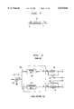
- FIG. 1 is an illustrative block diagram of a portion of a communications system embodying the principles of the invention
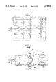
- FIG. 2 is an illustrative block diagram of a phase-splitting equalizer
- FIG. 3 is an illustrative block diagram of a portion of an adaptive filter for use in an equalizer
- FIG. 4 is an illustrative block diagram of a cross-coupled equalizer
- FIG. 5 is an illustrative block diagram of a four-filter equalizer
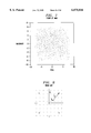
- FIG. 6 is an illustrative signal point plot of an output signal of an equalizer before convergence
- FIG. 7 is an illustrative signal point plot of an output signal of an equalizer for a system using the MMA blind equalization method
- FIG. 8 is an illustrative signal point plot illustrating the reduced signal point constellation of the RCA blind equalization method
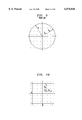
- FIG. 9 is an illustrative signal point plot illustrating the circular contour of the CMA blind equalization method
- FIG. 10 is an illustrative signal point plot illustrating the piecewise linear contours of the MMA blind equalization method
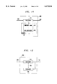
- FIGS. 11 and 12 are illustrative block diagrams of a portion of a receiver embodying the principles of the invention.
- FIGS. 13, 14, and 15 are illustrative signal point plots illustrating the piecewise linear contours of the MMA blind equalization method for a nonsquare constellation
- FIGS. 16 and 17 are illustrative signal point plots of an output signal of an equalizer for a communications system using a two-step MMA blind equalization method
- FIG. 18 shows a table providing a general comparison between the RCA, CMA, and MMA, blind equalization methods, without CHCF;
- FIG. 19 shows a table of illustrative data values for use in the RCA, CMA, and MMA, blind equalization methods
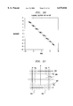
- FIG. 20 is an illustrative graph of an incorrect diagonal solution for a 64-CAP signal point constellation
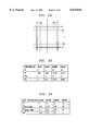
- FIG. 21 shows an illustrative partitioning of a signal point constellation using a windowing approach
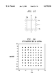
- FIG. 22 shows an illustrative partitioning of a signal point constellation using a half-constellation windowing approach
- FIG. 23 shows a table of illustrative data values for use in the half-constellation WMMA approach
- FIG. 24 shows a table of illustrative data values for comparing cost functions
- FIG. 25 shows an illustrative partitioning of a signal point constellation using an edge-point constellation windowing approach
- FIG. 26 is an illustrative signal point plot of an output signal of an equalizer using an LMS algorithm.
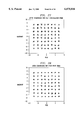
- FIGS. 27-28 are illustrative signal point plots of an output signal of an equalizer using a Half-Constellation WMMA algorithm and Edge-Point WMMA algorithm, respectively.
- FIG. 1 An illustrative high-level block diagram of a portion of a communications system embodying the principles of the invention is shown in FIG. 1.
- receiver 10 receives a CAP (carrierless, amplitude modulation, phase modulation) signal, which can be represented by:
- n and b n are discrete-valued multilevel symbols
- p(t) and p(t) are impulse responses which form a Hilbert pair
- T is the symbol period
- ⁇ (t) is additive noise introduced in the channel.
- an adaptive filter is, e.g., a fractionally spaced linear equalizer, which is hereafter simply referred to as an FSLE equalizer or, simply, an equalizer.
- phase-splitting FSLE equalizer 100 is shown in FIG. 2. It is assumed that FSLE equalizer 100 operates on an input signal comprising two dimensions: an in-phase component and a quadrature component.
- FSLE equalizer 100 comprises two parallel digital adaptive filters implemented as finite impulse response (FIR) filters 110 and 120. Equalizer 100 is called a "phase-splitting FSLE" because the two FIR filters 110 and 120 converge to in-phase and quadrature filters.
- FIR finite impulse response
- FIG. 3 Some illustrative details of the equalizer structure are shown in FIG. 3.
- the two FIR filters 110 and 120 share the same tapped delay line 115, which stores sequences of successive Analog-to-Digital Converter (A/ID) 125 samples r k .
- A/ID Analog-to-Digital Converter
- the outputs of the two adaptive FIR filters 110 and 120 as shown in FIG. 3 are computed at the symbol rate 1/T.
- the equalizer taps and input samples can be represented by a corresponding N-dimensional vector. As such, the following relationships are now defined:
- FIGS. 6 and 17 show an 64-CAP constellation before and after illustrative convergence using the MMA algorithm.
- decision devices 130 and 135 shown in FIG. 2 compare the sampled outputs y n and y n of equalizer 100 with valid symbol values a n and b n and makes a decision on which symbols have been transmitted. These sliced symbols will be denoted a n and b n .
- the receiver then computes the following in-phase and quadrature errors e n and e n :
- LMS least-mean-square
- ⁇ is the step size used in the tap adjustment algorithm.
- FIG. 4 a cross-coupled FSLE, 200, is shown.
- the A/D samples are first fed to two fixed in-phase and quadrature FIR filters, 210 and 205, respectively.
- the sampling rate 1/T' of A/D 125 is typically equal to four times the symbol rate 1/T.
- the outputs of the two fixed FIR filters are computed at a rate 1/T" that is consistent with the sampling theorem for analytic signals as known in the art.
- the output signals are then fed to equalizer 200 having a so-called cross-coupled structure.
- 1/T" is twice the symbol rate 1/T.
- the cross-coupled equalizer 200 uses two adaptive FIR filters 215a and 215b, each with tap vectors c n and d n .
- the same tap vector notations c n and d n (which have been used for the previous described equalizer 100 of FIG. 2) are used again.
- the tap vectors are different for the two types of equalizers.
- These two filters are each used twice to compute the outputs y n and y n of the equalizer.
- Let r n and r n be the output vectors of the in-phase and quadrature filters that are used to compute the outputs of the cross-coupled equalizer. The following definitions can be made:
- the complex output Y n of the equalizer can be written in the following compact way:
- the LMS algorithm for updating the complex tap vector C n can be written as:
- Four-filter equalizer 300 has the same general structure as cross-coupled FSLE 200 shown in FIG. 4, except that the adaptive portion consists of four different filters rather than two filters which are used twice. For this reason it is called a four-filter FSLE.
- the two output signals of equalizer 300 are computed as follows:
- the receiver then computes an error, E n , where:
- the most common tap updating algorithm is the LMS algorithm, which is a stochastic gradient algorithm that minimizes the mean square error (MSE), which is defined as:
- E[ ⁇ ] denotes expectation and e n and e n are in-phase and quadrature errors, respectively.
- the output signal of equalizer 100 is corrupted by a lot of intersymbol interference, as illustrated in FIG. 6.
- the latter represents experimental data obtained for a 64-CAP receiver using a phase-splitting FSLE as represented by FIG. 2.
- the receiver can compute meaningful errors E n by using the equalizer output signal Y n and the known sequence of transmitted symbols A n .
- tap adaptation is said to be done with "ideal reference” to distinguish it from decision directed tap adaptation.
- equalizer 100 has to be converged blindly.
- a decision-directed tap updating algorithm cannot be used to converge the equalizer, because the slicer makes too many wrong decisions, as should be apparent from FIG. 6.
- the philosophy of blind equalization is to use a tap adaptation algorithm that minimizes a cost function that is better suited to provide initial convergence of equalizer 100 than the MSE represented by equation (17).
- the cost fuictions used in the RCA, CMA, and MMA algorithms are described below.
- Convergence of an equalizer during blind start-up usually consists of two main steps. First, a blind equalization algorithm is used to open the "eye diagram.” (Hereafter, this will be referred to as “it opens the eye.”) Once the eye is open enough, the receiver switches to a decision directed tap adaptation algorithm.
- the error used in the tap updating algorithm is derived with respect to a signal constellation that has a smaller number of points than the received constellation.
- the signal constellation comprises 64 symbols.
- the reduced constellation typically consists of four signal points only, as shown in FIG. 8. It should be noted that the RCA algorithm requires the use of a decision device, e.g., a slicer, to select the closest signal point from the reduced constellation.
- the error between the received sample Y n and the closest signal point A r ,n of the reduced constellation is the complex number:
- the outputs y n and y n of this four-filter equalizer structure are computed from equations (13a) and (13b).
- the gradients of the cost function in equation (20) with respect to the four tap vectors are similar to the ones given in equations (22a) and (22b) and will not be repeated here.
- the tap updating algorithms are given by:
- the main advantage of RCA is its low cost of implementation because it is typically the least complex of blind equalization algorithms.
- the tap updating algorithms represented by equations (24a), (24b), (27) and (28) are the same as the standard LMS algorithms represented by equations (8a) and (8b) except that the slicer uses a different number of points.
- FIG. 16 shows an illustrative correct solution for a 64-CAP signal point constellation using the MMA blind equalization algorithm.
- the CMA algorithm minimizes the dispersion of the equalized samples Y n with respect to a circle with radius R. This is graphically illustrated in FIG. 9.
- the cost function in equation (29) is a true two-dimensional cost function which minimizes the dispersion of the equalizer complex output signal Y n with respect to a circular two-dimensional contour.
- CMA CMA tap updating algorithm
- MMA MMA
- rotator the output signal of the equalizer
- the need to use a rotator after the equalizer increases the cost of implementation of CMA for some type of applications.
- the MMA algorithm minimizes the dispersion of the equalizer output samples y n and y n around piecewise linear in-phase and quadrature contours.
- the contours become straight lines. This is graphically illustrated in FIG. 10 for a 64-point constellation.
- the multimodulus algorithm minimizes the following cost function:
- R(Y n ) and R(Y n ) take discrete positive values, which depend on the equalizer outputs Y n .
- FIGS. 6, 7, 16, and 17 The above-mentioned two-step blind equalization procedure utilizing the MMA algorithm is graphically illustrated by FIGS. 6, 7, 16, and 17 for equalizer 100.
- FIG. 6 represents experimental data obtained for a 64-CAP receiver using a phase-splitting FSLE as represented by FIG. 2.
- FIG. 7 illustrates the beginning of the MMA process convergence.
- the MMA technique converges the equalizer enough to clearly illustrate the 64-symbol signal space as 64 noisy clusters. Although these noisy clusters would, typically, not be acceptable for steady-state operation--the eye is open enough to allow the receiver to switch to a 64-point slicer and a decision-directed LMS algorithm.
- the end result is a much cleaner constellation, as shown in FIG. 17.
- a clean transition can be made between the two modes of adaptation, MMA and decision directed, when the symbol error rate is better than 10 -2 , although successful transitions have been observed for worse symbol error rates.
- the noisy clusters in FIG. 16 could be further reduced by decreasing the step size in the MMA tap adjustment algorithm. Indeed, in some applications it may be possible to eliminate the switching to a decision directed tap adaptation algorithm. However, it should be noted that this would increase the start-up time and the required amount of digital precision.
- the MMA algorithm for square constellations can be used without modification for nonsquare constellations. In this case, caution has to be exercised in the computation of the constant R, because the discrete levels for the symbols a n and b n do not all have the same probability of occurrence (described below). However, it has been found through computer simulations that convergence of the MMA algorithm is somewhat less reliable for nonsquare constellations than for square constellations. This can be corrected by using the modified MMA discussed in the following section.
- a 128-point signal constellation is obtained in the following way. First define a 144-point signal constellation using the symbol levels ⁇ 1, ⁇ 3, ⁇ 5, ⁇ 7, ⁇ 9, ⁇ 11, and then remove the four corner points in each quadrant.) Minimization of the dispersion of the equalizer output samples y n and y n is now done around piecewise straight lines. Again, this is done independently for y n and y n .
- the quadrature cost functions derived from equation (37) are:
- Two different moduli R 1 and R 2 are used in equations (47) because the symbols a n and b n used in the 128-point constellation have two sets of levels ⁇ 1, ⁇ 3, ⁇ 5, ⁇ 7 ⁇ and ⁇ 9, ⁇ 11 ⁇ which have a different probability of occurrence. More moduli can be used if there are more than two sets of symbol levels with different statistics.
- the moduli R 1 and R 2 in equations (47) are computed from equation (39) by evaluating the moments of the symbols over the set of symbol levels to which a given modulus applies (additionally described below).
- FIG. 13 which illustrates the Moduli for the in-phase dimension and which applies to the real symbols a n of a 128-CAP signal constellation.
- the moments of the symbols can be computed by considering the first quadrant only.
- the variance of the symbols becomes:
- the tap updating algorithms for the modified MMA algorithm are the same as the ones given in equations (40), (44), and (46), except that the constant R is replaced by either R 1 or R 2 depending on which equalizer output sample Y n is received.
- FIG. 14 illustrates the Moduli for the quadrature dimension and which applies to the symbols b n of the 128-CAP signal constellation. It should be apparent from FIG. 15, which represents the union of FIGS. 13 and 14, that the in-phase and quadrature tap updating algorithms need not use the same moduli R 1 or R 2 in a given symbol period.
- FIG. 19 shows illustrative values, for signal constellations of different sizes, of the constants R, R 1 , and R 2 , which are used in the tap updating algorithms of the RCA, CMA, and MMA, blind equalization techniques described above.
- the data shown in FIG. 19 assumes that the symbols a n and b n take the discrete values ⁇ 1, ⁇ 3, ⁇ 5, ⁇ 7, . . .
- the closed-form expressions for these constants are derived as described above.
- the RCA algorithm has less reliable convergence than either the CMA or MMA algorithms.
- these algorithms have both benefits and drawbacks.
- the CMA algorithm provides reliable convergence--thus avoiding incorrect diagonal solutions--but the CMA algorithm requires an expensive rotator.
- the MMA algorithm does not require an expensive rotator but is more susceptible than the CMA algorithm to incorrect convergence.
- Any blind convergence technique is affected by the distribution of the output signals, or samples, of the equalizer. As such, an increase in the number of symbol levels increases the distribution of the equalizer output samples, which--in turn--makes it more difficult to blindly converge the equalizer. This is illustrated by the following comparison between the MMA blind equalization algorithm and the standard LMS algorithm.
- the cost function minimizes the error between the equalizer's output signals Y n and an unknown sequence of transmitted symbols A n :
- the LMS-based error used during tap updating is equivalent to the error measured at the slicer and is a well-defined quantity.
- an equalizer can converge to optimal solutions when errors are directly calculated with respect to the inputs and outputs of the slicer.
- the MMA algorithm is examined to explore what are the residual values of the cost function CF.
- Equation (80) gives a simple way to express the cost function after convergence and steady-state values of the cost function CF a ,n can be easily calculated.
- the number of symbol levels m (in magnitude) can be computed from the number of constellation points C for C-CAP: ##EQU18##
- This means that the optimum convergence for a blind equalizer can only be achieved for 4-CAP with m 1.
- Residual values of the cost function CF a ,n significantly increase with increasing m.
- residual values of CF a ,n become so large that a blind equalizer fails to converge.
- Residual values of CF a ,n are increasing functions of the number m, and convergence of an equalizer is directly affected by those values. In conclusion, the reliability of a blind algorithm is highly degraded with increasing values of m. When the residual values of CF a ,n increase beyond some quantity, the eye diagram fails to open. It has been experimentally found that a standard MMA is only effective for CAP applications with m less that eight which corresponds to 256-CAP.
- a blind convergence technique is restricted to using a subset of the equalizer output samples. This improves the ability to blindly converge the equalizer notwithstanding an increase in symbol levels.
- a receiver implements a windowed MMA (WMMA) approach.
- WMMA windowed MMA
- a sample window overlays the two-dimensional plane representing the set of equalizer output samples. Only those equalizer output samples appearing within the sample window are used during filter adaptation.
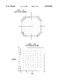
- FIG. 21 An example is shown in FIG. 21, where a sample window is defined by two dotted lines along each dimension--dotted lines 601 and 602 for the in-phase dimension, and dotted lines 603 and 604 for the quadrature phase dimension. These dotted lines form both an exclusion area 600 and a sample window within the signal space.
- WMMA only those samples, y n ,w, falling within the window, i.e., outside the exclusion area, are used during filter adaptation. This is in contrast to MMA, which uses all of the samples.
- the size of the window determines the set of data, y n ,w, used during filter adaptation, and therefore effects the convergence of the equalizer.
- the windowed MMA approach two different variations of the windowed MMA approach are described below.
- the first variation is “Half-Constellation WMMA” and the second variation is “Edge-Point WMMA.”
- the size of the window is varied as a function of the value of the single parameter m w , which results in a square exclusion area.
- each dotted line could be associated with a different parameter value thus yielding non-square exclusion areas.
- a half-constellation window is shown in FIG. 22 for a 64-CAP constellation.
- the samples y n are divided into two sets by the window boundaries m w with
- the cost function CF is redefined as:
- the window boundary m w is defined as:
- m indicates the number of symbol levels, and the magnitude of the highest symbol level is given by 2m-1.
- the window boundary m w is defined in such a way that the same number of inner-point and outer-point symbols a n are included around the constant R.
- the data, y n ,w, used to update the taps are symmetrically distributed on both sides of R.
- It is called half-constellation WMMA because the number of partial symbols, a n ,w, that construct the new constellation is half the number of the original symbols a n .
- the constant R w needs to be evaluated with respect to symbols a n ,w.
- the cost function CF w now converges to symbols a n ,w :
- the parameter w denotes the number of symbol levels required for the constellation including a n ,w.
- Equation (87) means that half the number of the original symbol levels m is required.
- the parameter M denotes the number of the largest symbol levels and the parameter M w denotes the number of symbol levels below the window boundary m w .
- the parameters are given by:
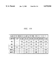
- a comparison of residual values of cost functions for MMA and half-constellation WMMA is provided in the Table shown in FIG. 24.
- This table shows that the cost function for 16-CAP becomes zero, and that a reduction of about 5 dB can be obtained for other CAP systems.
- the cost function CF a ,n becomes optimum for 16-CAP.
- the cost function CF a ,n is reduced. Reduction of the residual values of the cost function CF a ,n leads to improved reliability and convergence rate of blind equalizers.
- Edge-point WMMA is proposed as the second application of WMMA.
- the cost function for half-constellation WMMA in equation (81) can be directly applied to edge-point WMMA, except that a modification is made for the sample window parameters.
- the window parameters are illustrated in FIG. 25, where the window boundary m w is defined as:
- the symbols a n ,w are given by a 2m-1 .
- the symbols used for filter adaptation are only those that have the largest values.
- FIG. 25 shows that these symbols are geometrically located at the edge of the original constellation. Because only one symbol level is involved, the calculation of R w is simply given by:
- Equation (96) further leads to the result:
- Equation (97) shows that zero value can be achieved with such a cost function. That is, with edge-point WMMA, the cost function becomes optimum for any CAP system.
- edge-point and half-constellation MMA are basically the same except that they use different window parameters. However, the difference in parameters results in different performance. Theoretically, optimum convergence can only be achieved for 16-CAP with half-constellation WMMA, and can be achieved for any CAP application with edge-point WMMA under conditions to be discussed later.
- edge-point constellation The design parameters of the edge-point constellation are simple and easy to implement. However, expected performance cannot be achieved for high level CAP applications because other factors also affect convergence, such as the lack of enough data samples y n .
- the cost functions can be applied to both half-constellation and edge-point WMMAs by using different definitions for y n ,w, as described above.
- the gradients of the cost function in equation (98) with respect to the tap vectors c n and d n are equal to:
- the taps of the filter are then updated in a stochastic fashion in the opposite direction of the gradient:
- the samples y n ,w are normally calculated by using a comparator, or a look-up table.
- a nonlinear function ⁇ ( ⁇ ) is proposed to determine partial samples y n ,w.
- the function ⁇ ( ⁇ ) is defined as:
- the cost function CF can be rewritten as:
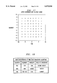
- FIGS. 16, and 26-28 show illustrative plots of converged signal constellations for the various algorithms based on computer simulation.
- FIG. 16 shows the signal constellation after converging with MMA
- FIG. 26 shows the signal constellation after converging with LMS. These two figures together show that even though initial convergence can be achieved with blind algorithms, the LMS algorithm is needed to obtain optimal convergence.
- FIG. 27 shows the converged constellation with the half-constellation WMMA
- FIG. 28 shows the converged constellation with the edge-point WMMA. From FIGS. 27 and 28, it can be observed that the convergence performance is improved by using the half-constellation WMMA, and is further improved by using the edge-point WMMA. In fact, a comparison of FIGS.
- windowed MMA be limited to applications with a limited number of symbol levels. For very large constellation, a good performance may be difficult to obtain because of the lack of sufficient equalizer output samples during filter adaptation.
- FIG. 11 illustrates an embodiment representative of a digital signal processor 400 that is programmed to implement an FSLE in accordance with the principles of the invention.
- Digital signal processor 400 comprises a central processing unit (processor) 405 and memory 410.
- a portion of memory 410 is used to store program instructions that, when executed by processor 405, implement the windowed-MMA type algorithm. This portion of memory is shown as 411.
- Another portion of memory, 412 is used to store tap coefficient values that are updated by processor 405 in accordance with the inventive concept. It is assumed that a received signal 404 is applied to processor 405, which equalizes this signal in accordance with the inventive concept to provide a output signal 406.
- output signal 406 represents a sequence of output samples of an equalizer.
- a digital signal processor may, additionally, further process received signal 404 before deriving output signal 406.
- An illustrative software program is not described herein since, after learning of the windowed-MMA type algorithms as described herein, such a program is within the capability of one skilled in the art.
- any equalizer structures can be implemented by digital signal processor 400 in accordance with the inventive concept.
- FIG. 12 illustrates another alternative embodiment of the inventive concept.
- Circuitry 500 comprises a central processing unit (processor) 505, and an equalizer 510.
- processor central processing unit
- equalizer 510 includes at least one tap-coefficient register for storing values for corresponding tap coefficient vectors (e.g., as shown in FIG. 3).
- Processor 505 includes memory, not shown, similar to memory 410 of FIG. 11 for implementing the windowed-MMA type algorithms.
- Equalizer output signal 511 which represents a sequence of equalizer output samples, is applied to processor 505. The latter analyzes equalizer output signal 511, in accordance with the inventive concept, to adapt values of the tap coefficients in such a way as to converge to a correct solution.
- inventive concept was described in the context of an FSLE, the inventive concept is applicable to other forms of adaptive filters, such as, but not limited to, a decision feedback equalizer (DFE).
- DFE decision feedback equalizer
- the inventive concept is applicable to all forms of communications systems, e.g., broadcast networks, e.g., high-definition television (HDTV), point-to-multipoint Networks like fiber to the curb (mentioned above), signal identification, or classification, applications like wire-tapping, etc.
- broadcast networks e.g., high-definition television (HDTV), point-to-multipoint Networks like fiber to the curb (mentioned above), signal identification, or classification, applications like wire-tapping, etc.
- inventive concept was described in the context of a modified MMA algorithm, the inventive concept is applicable to other forms of equalization.
Landscapes
- Engineering & Computer Science (AREA)
- Signal Processing (AREA)
- Computer Networks & Wireless Communication (AREA)
- Physics & Mathematics (AREA)
- Spectroscopy & Molecular Physics (AREA)
- Power Engineering (AREA)
- Multimedia (AREA)
- Cable Transmission Systems, Equalization Of Radio And Reduction Of Echo (AREA)
- Digital Transmission Methods That Use Modulated Carrier Waves (AREA)
- Circuits Of Receivers In General (AREA)
- Filters That Use Time-Delay Elements (AREA)
- Image Generation (AREA)
Priority Applications (7)
| Application Number | Priority Date | Filing Date | Title |
|---|---|---|---|
| US08/757,207 US6075816A (en) | 1996-11-27 | 1996-11-27 | Windowing technique for blind equalization |
| CA002217839A CA2217839C (en) | 1996-11-27 | 1997-10-09 | A windowing technique for blind equalization |
| TW086115068A TW362313B (en) | 1996-11-27 | 1997-10-14 | A windowing technique for blind equalization |
| JP9330857A JPH10178371A (ja) | 1996-11-27 | 1997-11-17 | 受信器において等化を実行するための方法および装置 |
| DE69735124T DE69735124T2 (de) | 1996-11-27 | 1997-11-18 | Fenstertechnik für blinde Entzerrung |
| EP97309276A EP0845891B1 (de) | 1996-11-27 | 1997-11-18 | Fenstertechnik für blinde Entzerrung |
| KR1019970063150A KR19980042785A (ko) | 1996-11-27 | 1997-11-26 | 블라인드 등화를 위한 윈도우즈 기술 |
Applications Claiming Priority (1)
| Application Number | Priority Date | Filing Date | Title |
|---|---|---|---|
| US08/757,207 US6075816A (en) | 1996-11-27 | 1996-11-27 | Windowing technique for blind equalization |
Publications (1)
| Publication Number | Publication Date |
|---|---|
| US6075816A true US6075816A (en) | 2000-06-13 |
Family
ID=25046846
Family Applications (1)
| Application Number | Title | Priority Date | Filing Date |
|---|---|---|---|
| US08/757,207 Expired - Lifetime US6075816A (en) | 1996-11-27 | 1996-11-27 | Windowing technique for blind equalization |
Country Status (7)
| Country | Link |
|---|---|
| US (1) | US6075816A (de) |
| EP (1) | EP0845891B1 (de) |
| JP (1) | JPH10178371A (de) |
| KR (1) | KR19980042785A (de) |
| CA (1) | CA2217839C (de) |
| DE (1) | DE69735124T2 (de) |
| TW (1) | TW362313B (de) |
Cited By (22)
| Publication number | Priority date | Publication date | Assignee | Title |
|---|---|---|---|---|
| US6337878B1 (en) * | 1999-03-03 | 2002-01-08 | Nxt Wave Communications | Adaptive equalizer with decision directed constant modulus algorithm |
| US20020007257A1 (en) * | 1999-11-04 | 2002-01-17 | Eilon Riess | Reliable symbols as a means of improving the performance of information transmission systems |
| US20020037062A1 (en) * | 1999-11-04 | 2002-03-28 | Eilon Riess | Reliable symbols as a means of improving the performance of information transmission systems |
| US6381623B1 (en) * | 1998-06-04 | 2002-04-30 | Siemens Aktiengesellschaft | Method for adaptive filter adjustment in a QAM/CAP system |
| US20020080896A1 (en) * | 1999-11-04 | 2002-06-27 | Verticalband, Limited | Fast, blind equalization techniques using reliable symbols |
| US6426972B1 (en) * | 1998-06-19 | 2002-07-30 | Nxtwave Communications | Reduced complexity equalizer for multi mode signaling |
| WO2002071607A1 (en) * | 2001-03-02 | 2002-09-12 | União Brasileira De Educacão E Assistência | Concurrent process for blind deconvolution of digital signals |
| WO2003090350A1 (en) * | 2002-04-17 | 2003-10-30 | Thomson Licensing S.A. | Equalizer mode switch |
| US20040091056A1 (en) * | 1998-04-03 | 2004-05-13 | Tellabs Operations, Inc. A Delaware Corporation | Spectrally constrained impulse shortening filter for a discrete multi-tone receiver |
| US20040114681A1 (en) * | 2002-12-17 | 2004-06-17 | Ron Rotstein | Method for improving performance of wireless systems at high speeds |
| US20040186865A1 (en) * | 2003-01-21 | 2004-09-23 | Infineon Technologies Ag | Method and device for reducing the crest factor of a signal |
| US20040186867A1 (en) * | 2003-01-21 | 2004-09-23 | Infineon Technologies Ag | Method and device for reducing the crest factor of a signal |
| US20040246890A1 (en) * | 1996-08-22 | 2004-12-09 | Marchok Daniel J. | OFDM/DMT/ digital communications system including partial sequence symbol processing |
| US20050220220A1 (en) * | 2002-03-19 | 2005-10-06 | Thomas Licensing S.A. | Slicing algorithm for multi-level modulation equalizing schemes |
| US20070195903A1 (en) * | 2004-05-12 | 2007-08-23 | Thomson Licensing | Constellation Location Dependent Step Sizes For Equalizer Error Signals |
| US20080043829A1 (en) * | 2004-05-12 | 2008-02-21 | Dong-Chang Shiue | Noise Power Estimate Based Equalizer Lock Detector |
| US20080043827A1 (en) * | 2004-02-20 | 2008-02-21 | Markku Renfors | Channel Equalization |
| US20080298483A1 (en) * | 1996-08-22 | 2008-12-04 | Tellabs Operations, Inc. | Apparatus and method for symbol alignment in a multi-point OFDM/DMT digital communications system |
| US20090003421A1 (en) * | 1998-05-29 | 2009-01-01 | Tellabs Operations, Inc. | Time-domain equalization for discrete multi-tone systems |
| US20090285274A1 (en) * | 2004-05-12 | 2009-11-19 | Thomson Licensing | Equalizer lock detection based on the location of received signal points |
| US20100104035A1 (en) * | 1996-08-22 | 2010-04-29 | Marchok Daniel J | Apparatus and method for clock synchronization in a multi-point OFDM/DMT digital communications system |
| US9014250B2 (en) | 1998-04-03 | 2015-04-21 | Tellabs Operations, Inc. | Filter for impulse response shortening with additional spectral constraints for multicarrier transmission |
Families Citing this family (3)
| Publication number | Priority date | Publication date | Assignee | Title |
|---|---|---|---|---|
| GB2364621A (en) * | 2000-07-10 | 2002-01-30 | Verticalband Ltd | Adaptive blind equaliser using reliable symbols |
| JP5471761B2 (ja) * | 2010-04-15 | 2014-04-16 | 富士通株式会社 | 受信回路 |
| CN102143104B (zh) * | 2011-03-28 | 2013-08-21 | 上海交通大学 | 具有双重叠结构的时域自适应判决反馈均衡器 |
Citations (7)
| Publication number | Priority date | Publication date | Assignee | Title |
|---|---|---|---|---|
| US4894847A (en) * | 1987-05-26 | 1990-01-16 | Hayes Microcomputer Products, Inc. | High speed half duplex modem with fast turnaround protocol |
| US5157690A (en) * | 1990-10-30 | 1992-10-20 | Level One Communications, Inc. | Adaptive convergent decision feedback equalizer |
| US5195106A (en) * | 1990-11-14 | 1993-03-16 | Motorola, Inc. | Method for channel adaptive detecting/equalize |
| US5303263A (en) * | 1991-06-25 | 1994-04-12 | Oki Electric Industry Co., Ltd. | Transmission channel characteristic equalizer |
| US5414732A (en) * | 1993-05-17 | 1995-05-09 | Loral Aerospace Corp. | Adaptive equalizer and method for operation at high symbol rates |
| US5506871A (en) * | 1993-06-02 | 1996-04-09 | Samsung Electronics Co., Ltd. | Adaptive equalizing system for digital communications |
| US5654765A (en) * | 1993-11-18 | 1997-08-05 | Goldstar Co., Ltd. | Channel equalizer for digital television receiver having an initial coefficient storage unit |
-
1996
- 1996-11-27 US US08/757,207 patent/US6075816A/en not_active Expired - Lifetime
-
1997
- 1997-10-09 CA CA002217839A patent/CA2217839C/en not_active Expired - Fee Related
- 1997-10-14 TW TW086115068A patent/TW362313B/zh not_active IP Right Cessation
- 1997-11-17 JP JP9330857A patent/JPH10178371A/ja active Pending
- 1997-11-18 EP EP97309276A patent/EP0845891B1/de not_active Expired - Lifetime
- 1997-11-18 DE DE69735124T patent/DE69735124T2/de not_active Expired - Lifetime
- 1997-11-26 KR KR1019970063150A patent/KR19980042785A/ko not_active Withdrawn
Patent Citations (7)
| Publication number | Priority date | Publication date | Assignee | Title |
|---|---|---|---|---|
| US4894847A (en) * | 1987-05-26 | 1990-01-16 | Hayes Microcomputer Products, Inc. | High speed half duplex modem with fast turnaround protocol |
| US5157690A (en) * | 1990-10-30 | 1992-10-20 | Level One Communications, Inc. | Adaptive convergent decision feedback equalizer |
| US5195106A (en) * | 1990-11-14 | 1993-03-16 | Motorola, Inc. | Method for channel adaptive detecting/equalize |
| US5303263A (en) * | 1991-06-25 | 1994-04-12 | Oki Electric Industry Co., Ltd. | Transmission channel characteristic equalizer |
| US5414732A (en) * | 1993-05-17 | 1995-05-09 | Loral Aerospace Corp. | Adaptive equalizer and method for operation at high symbol rates |
| US5506871A (en) * | 1993-06-02 | 1996-04-09 | Samsung Electronics Co., Ltd. | Adaptive equalizing system for digital communications |
| US5654765A (en) * | 1993-11-18 | 1997-08-05 | Goldstar Co., Ltd. | Channel equalizer for digital television receiver having an initial coefficient storage unit |
Cited By (45)
| Publication number | Priority date | Publication date | Assignee | Title |
|---|---|---|---|---|
| US20080298483A1 (en) * | 1996-08-22 | 2008-12-04 | Tellabs Operations, Inc. | Apparatus and method for symbol alignment in a multi-point OFDM/DMT digital communications system |
| US8547823B2 (en) | 1996-08-22 | 2013-10-01 | Tellabs Operations, Inc. | OFDM/DMT/ digital communications system including partial sequence symbol processing |
| US20100104035A1 (en) * | 1996-08-22 | 2010-04-29 | Marchok Daniel J | Apparatus and method for clock synchronization in a multi-point OFDM/DMT digital communications system |
| US20040246890A1 (en) * | 1996-08-22 | 2004-12-09 | Marchok Daniel J. | OFDM/DMT/ digital communications system including partial sequence symbol processing |
| US8139471B2 (en) | 1996-08-22 | 2012-03-20 | Tellabs Operations, Inc. | Apparatus and method for clock synchronization in a multi-point OFDM/DMT digital communications system |
| US8665859B2 (en) | 1996-08-22 | 2014-03-04 | Tellabs Operations, Inc. | Apparatus and method for clock synchronization in a multi-point OFDM/DMT digital communications system |
| US20120183034A1 (en) * | 1998-04-03 | 2012-07-19 | Tellabs Operations, Inc. | Spectrally constrained impulse shortening filter for a discrete multi-tone receiver |
| US7254178B2 (en) * | 1998-04-03 | 2007-08-07 | Tellabs Operations, Inc. | Spectrally constrained impulse shortening filter for a discrete multi-tone receiver |
| US20090022216A1 (en) * | 1998-04-03 | 2009-01-22 | Tellabs Operations, Inc. | Spectrally constrained impulse shortening filter for a discrete multi-tone receiver |
| US7430242B2 (en) | 1998-04-03 | 2008-09-30 | Tellabs Operations, Inc. | Spectrally constrained impulse shortening filter for a discrete multi-tone receiver |
| US20040091056A1 (en) * | 1998-04-03 | 2004-05-13 | Tellabs Operations, Inc. A Delaware Corporation | Spectrally constrained impulse shortening filter for a discrete multi-tone receiver |
| US8102928B2 (en) | 1998-04-03 | 2012-01-24 | Tellabs Operations, Inc. | Spectrally constrained impulse shortening filter for a discrete multi-tone receiver |
| US9014250B2 (en) | 1998-04-03 | 2015-04-21 | Tellabs Operations, Inc. | Filter for impulse response shortening with additional spectral constraints for multicarrier transmission |
| US20070230562A1 (en) * | 1998-04-03 | 2007-10-04 | Tellabs Operations, Inc. | Spectrally constrained impulse shortening filter for a discrete multi-tone receiver |
| US8315299B2 (en) | 1998-05-29 | 2012-11-20 | Tellabs Operations, Inc. | Time-domain equalization for discrete multi-tone systems |
| US20090003421A1 (en) * | 1998-05-29 | 2009-01-01 | Tellabs Operations, Inc. | Time-domain equalization for discrete multi-tone systems |
| US7916801B2 (en) | 1998-05-29 | 2011-03-29 | Tellabs Operations, Inc. | Time-domain equalization for discrete multi-tone systems |
| US6381623B1 (en) * | 1998-06-04 | 2002-04-30 | Siemens Aktiengesellschaft | Method for adaptive filter adjustment in a QAM/CAP system |
| US6426972B1 (en) * | 1998-06-19 | 2002-07-30 | Nxtwave Communications | Reduced complexity equalizer for multi mode signaling |
| US6337878B1 (en) * | 1999-03-03 | 2002-01-08 | Nxt Wave Communications | Adaptive equalizer with decision directed constant modulus algorithm |
| US7110923B2 (en) | 1999-11-04 | 2006-09-19 | Verticalband, Limited | Fast, blind equalization techniques using reliable symbols |
| US20030016769A9 (en) * | 1999-11-04 | 2003-01-23 | Verticalband, Limited | Fast, blind equalization techniques using reliable symbols |
| US7085691B2 (en) * | 1999-11-04 | 2006-08-01 | Verticalband, Limited | Reliable symbols as a means of improving the performance of information transmission systems |
| US20020007257A1 (en) * | 1999-11-04 | 2002-01-17 | Eilon Riess | Reliable symbols as a means of improving the performance of information transmission systems |
| US20020037062A1 (en) * | 1999-11-04 | 2002-03-28 | Eilon Riess | Reliable symbols as a means of improving the performance of information transmission systems |
| US7143013B2 (en) | 1999-11-04 | 2006-11-28 | Verticalband, Limited | Reliable symbols as a means of improving the performance of information transmission systems |
| US20020080896A1 (en) * | 1999-11-04 | 2002-06-27 | Verticalband, Limited | Fast, blind equalization techniques using reliable symbols |
| US20040076249A1 (en) * | 2001-03-02 | 2004-04-22 | Comparsi De Castro Fernando Cesar | Concurrent process for blind deconvolution of digital signals |
| WO2002071607A1 (en) * | 2001-03-02 | 2002-09-12 | União Brasileira De Educacão E Assistência | Concurrent process for blind deconvolution of digital signals |
| CN100544196C (zh) * | 2001-03-02 | 2009-09-23 | 巴西教育与援助协会 | 数字信号盲解去卷积的同步处理方法及其系统 |
| US20050220220A1 (en) * | 2002-03-19 | 2005-10-06 | Thomas Licensing S.A. | Slicing algorithm for multi-level modulation equalizing schemes |
| US7894513B2 (en) * | 2002-03-19 | 2011-02-22 | Thomson Licensing | Slicing algorithm for multi-level modulation equalizing schemes |
| US7492818B2 (en) | 2002-04-17 | 2009-02-17 | Thomson Licensing | Equalizer mode switch |
| CN100527612C (zh) * | 2002-04-17 | 2009-08-12 | 汤姆森特许公司 | 用于自动均衡器模式选择的设备和方法 |
| KR100916378B1 (ko) | 2002-04-17 | 2009-09-18 | 톰슨 라이센싱 | 등화기 모드 스위치 |
| WO2003090350A1 (en) * | 2002-04-17 | 2003-10-30 | Thomson Licensing S.A. | Equalizer mode switch |
| US20050254568A1 (en) * | 2002-04-17 | 2005-11-17 | Ivonete Markman | Equalizer mode switch |
| US20040114681A1 (en) * | 2002-12-17 | 2004-06-17 | Ron Rotstein | Method for improving performance of wireless systems at high speeds |
| US20040186867A1 (en) * | 2003-01-21 | 2004-09-23 | Infineon Technologies Ag | Method and device for reducing the crest factor of a signal |
| US20040186865A1 (en) * | 2003-01-21 | 2004-09-23 | Infineon Technologies Ag | Method and device for reducing the crest factor of a signal |
| US7936851B2 (en) | 2004-02-20 | 2011-05-03 | Nokia Corporation | Channel equalization |
| US20080043827A1 (en) * | 2004-02-20 | 2008-02-21 | Markku Renfors | Channel Equalization |
| US20090285274A1 (en) * | 2004-05-12 | 2009-11-19 | Thomson Licensing | Equalizer lock detection based on the location of received signal points |
| US20080043829A1 (en) * | 2004-05-12 | 2008-02-21 | Dong-Chang Shiue | Noise Power Estimate Based Equalizer Lock Detector |
| US20070195903A1 (en) * | 2004-05-12 | 2007-08-23 | Thomson Licensing | Constellation Location Dependent Step Sizes For Equalizer Error Signals |
Also Published As
| Publication number | Publication date |
|---|---|
| KR19980042785A (ko) | 1998-08-17 |
| DE69735124T2 (de) | 2006-08-03 |
| CA2217839C (en) | 2001-09-04 |
| CA2217839A1 (en) | 1998-05-27 |
| TW362313B (en) | 1999-06-21 |
| EP0845891A3 (de) | 2001-03-21 |
| EP0845891A2 (de) | 1998-06-03 |
| JPH10178371A (ja) | 1998-06-30 |
| DE69735124D1 (de) | 2006-04-06 |
| EP0845891B1 (de) | 2006-01-18 |
Similar Documents
| Publication | Publication Date | Title |
|---|---|---|
| US5809074A (en) | Technique for improving the blind convergence of an adaptive equalizer using a transition algorithm | |
| EP0845891B1 (de) | Fenstertechnik für blinde Entzerrung | |
| US5835731A (en) | Technique for improving the blind convergence of a two-filter adaptive equalizer | |
| US5940440A (en) | Generalized multimodulus technique for blind equalization | |
| US6069917A (en) | Blind training of a decision feedback equalizer | |
| US6490318B1 (en) | Phase-compensating constant modulus algorithm | |
| US6259743B1 (en) | Automatic constellation phase recovery in blind start-up of a dual mode CAP-QAM receiver | |
| US6314134B1 (en) | Blind equalization algorithm with joint use of the constant modulus algorithm and the multimodulus algorithm | |
| US5793807A (en) | Multimodulus blind eqalization using piecewise linear contours | |
| EP1063822B1 (de) | Algorithmus zur blinden Entzerrung unter Verwendung von sowohl der Konstanten R als auch von den entschiedenen Symbolen | |
| EP0969635B1 (de) | Blindentzerrung in Empfängern mit sowohl CAP- als auch QAM-Betriebsmoden | |
| KR100398449B1 (ko) | 블라인드 판정 궤환 등화 장치 및 그 방법 |
Legal Events
| Date | Code | Title | Description |
|---|---|---|---|
| AS | Assignment |
Owner name: LUCENT TECHNOLOGIES INC., NEW JERSEY Free format text: ASSIGNMENT OF ASSIGNORS INTEREST;ASSIGNORS:WERNER, JEAN-JACQUES;YANG, JIAN;REEL/FRAME:008325/0020 Effective date: 19961126 |
|
| STCF | Information on status: patent grant |
Free format text: PATENTED CASE |
|
| AS | Assignment |
Owner name: THE CHASE MANHATTAN BANK, AS COLLATERAL AGENT, TEX Free format text: CONDITIONAL ASSIGNMENT OF AND SECURITY INTEREST IN PATENT RIGHTS;ASSIGNOR:LUCENT TECHNOLOGIES INC. (DE CORPORATION);REEL/FRAME:011722/0048 Effective date: 20010222 |
|
| FEPP | Fee payment procedure |
Free format text: PAYOR NUMBER ASSIGNED (ORIGINAL EVENT CODE: ASPN); ENTITY STATUS OF PATENT OWNER: LARGE ENTITY |
|
| FPAY | Fee payment |
Year of fee payment: 4 |
|
| AS | Assignment |
Owner name: LUCENT TECHNOLOGIES INC., NEW JERSEY Free format text: TERMINATION AND RELEASE OF SECURITY INTEREST IN PATENT RIGHTS;ASSIGNOR:JPMORGAN CHASE BANK, N.A. (FORMERLY KNOWN AS THE CHASE MANHATTAN BANK), AS ADMINISTRATIVE AGENT;REEL/FRAME:018590/0047 Effective date: 20061130 |
|
| FPAY | Fee payment |
Year of fee payment: 8 |
|
| FPAY | Fee payment |
Year of fee payment: 12 |
|
| AS | Assignment |
Owner name: CREDIT SUISSE AG, NEW YORK Free format text: SECURITY INTEREST;ASSIGNOR:ALCATEL-LUCENT USA INC.;REEL/FRAME:030510/0627 Effective date: 20130130 |
|
| AS | Assignment |
Owner name: ALCATEL-LUCENT USA INC., NEW JERSEY Free format text: RELEASE BY SECURED PARTY;ASSIGNOR:CREDIT SUISSE AG;REEL/FRAME:033950/0261 Effective date: 20140819 |