US6086353A - Two-stage electric injection unit with rotating plunger - Google Patents
Two-stage electric injection unit with rotating plunger Download PDFInfo
- Publication number
- US6086353A US6086353A US09/024,731 US2473198A US6086353A US 6086353 A US6086353 A US 6086353A US 2473198 A US2473198 A US 2473198A US 6086353 A US6086353 A US 6086353A
- Authority
- US
- United States
- Prior art keywords
- plunger
- accumulator
- injection
- screw
- molding machine
- Prior art date
- Legal status (The legal status is an assumption and is not a legal conclusion. Google has not performed a legal analysis and makes no representation as to the accuracy of the status listed.)
- Expired - Lifetime
Links
- 239000007924 injection Substances 0.000 title claims abstract description 107
- 238000002347 injection Methods 0.000 title claims abstract description 107
- 239000000463 material Substances 0.000 claims abstract description 29
- 230000007246 mechanism Effects 0.000 claims abstract description 20
- 238000001746 injection moulding Methods 0.000 claims description 24
- 239000000155 melt Substances 0.000 claims description 12
- 238000013461 design Methods 0.000 description 18
- 230000006870 function Effects 0.000 description 17
- 239000004033 plastic Substances 0.000 description 14
- 229920003023 plastic Polymers 0.000 description 14
- 230000008901 benefit Effects 0.000 description 11
- 230000001965 increasing effect Effects 0.000 description 10
- 238000005516 engineering process Methods 0.000 description 7
- 230000006872 improvement Effects 0.000 description 7
- 238000010276 construction Methods 0.000 description 6
- 230000008878 coupling Effects 0.000 description 6
- 238000010168 coupling process Methods 0.000 description 6
- 238000005859 coupling reaction Methods 0.000 description 6
- 238000005461 lubrication Methods 0.000 description 4
- 238000000465 moulding Methods 0.000 description 4
- 238000001125 extrusion Methods 0.000 description 3
- 230000009467 reduction Effects 0.000 description 3
- 230000002441 reversible effect Effects 0.000 description 3
- 238000004140 cleaning Methods 0.000 description 2
- 230000003247 decreasing effect Effects 0.000 description 2
- 239000012530 fluid Substances 0.000 description 2
- 238000012545 processing Methods 0.000 description 2
- 230000002829 reductive effect Effects 0.000 description 2
- 239000011347 resin Substances 0.000 description 2
- 229920005989 resin Polymers 0.000 description 2
- 229920001169 thermoplastic Polymers 0.000 description 2
- 239000004416 thermosoftening plastic Substances 0.000 description 2
- 230000009471 action Effects 0.000 description 1
- 230000002411 adverse Effects 0.000 description 1
- 230000004075 alteration Effects 0.000 description 1
- 238000013459 approach Methods 0.000 description 1
- 230000015556 catabolic process Effects 0.000 description 1
- 230000008859 change Effects 0.000 description 1
- 239000000356 contaminant Substances 0.000 description 1
- 230000008030 elimination Effects 0.000 description 1
- 238000003379 elimination reaction Methods 0.000 description 1
- 230000002708 enhancing effect Effects 0.000 description 1
- 230000000670 limiting effect Effects 0.000 description 1
- 238000004519 manufacturing process Methods 0.000 description 1
- 238000005297 material degradation process Methods 0.000 description 1
- 230000013011 mating Effects 0.000 description 1
- 238000000034 method Methods 0.000 description 1
- 238000012986 modification Methods 0.000 description 1
- 230000004048 modification Effects 0.000 description 1
- 230000008569 process Effects 0.000 description 1
- 238000010926 purge Methods 0.000 description 1
- 238000004513 sizing Methods 0.000 description 1
- 239000012899 standard injection Substances 0.000 description 1
- 239000000126 substance Substances 0.000 description 1
- 238000006467 substitution reaction Methods 0.000 description 1
- 239000012815 thermoplastic material Substances 0.000 description 1
- 238000012546 transfer Methods 0.000 description 1
Images


Classifications
-
- B—PERFORMING OPERATIONS; TRANSPORTING
- B29—WORKING OF PLASTICS; WORKING OF SUBSTANCES IN A PLASTIC STATE IN GENERAL
- B29C—SHAPING OR JOINING OF PLASTICS; SHAPING OF MATERIAL IN A PLASTIC STATE, NOT OTHERWISE PROVIDED FOR; AFTER-TREATMENT OF THE SHAPED PRODUCTS, e.g. REPAIRING
- B29C45/00—Injection moulding, i.e. forcing the required volume of moulding material through a nozzle into a closed mould; Apparatus therefor
- B29C45/02—Transfer moulding, i.e. transferring the required volume of moulding material by a plunger from a "shot" cavity into a mould cavity
-
- B—PERFORMING OPERATIONS; TRANSPORTING
- B29—WORKING OF PLASTICS; WORKING OF SUBSTANCES IN A PLASTIC STATE IN GENERAL
- B29C—SHAPING OR JOINING OF PLASTICS; SHAPING OF MATERIAL IN A PLASTIC STATE, NOT OTHERWISE PROVIDED FOR; AFTER-TREATMENT OF THE SHAPED PRODUCTS, e.g. REPAIRING
- B29C45/00—Injection moulding, i.e. forcing the required volume of moulding material through a nozzle into a closed mould; Apparatus therefor
- B29C45/17—Component parts, details or accessories; Auxiliary operations
- B29C45/46—Means for plasticising or homogenising the moulding material or forcing it into the mould
- B29C45/53—Means for plasticising or homogenising the moulding material or forcing it into the mould using injection ram or piston
-
- B—PERFORMING OPERATIONS; TRANSPORTING
- B29—WORKING OF PLASTICS; WORKING OF SUBSTANCES IN A PLASTIC STATE IN GENERAL
- B29C—SHAPING OR JOINING OF PLASTICS; SHAPING OF MATERIAL IN A PLASTIC STATE, NOT OTHERWISE PROVIDED FOR; AFTER-TREATMENT OF THE SHAPED PRODUCTS, e.g. REPAIRING
- B29C45/00—Injection moulding, i.e. forcing the required volume of moulding material through a nozzle into a closed mould; Apparatus therefor
- B29C45/17—Component parts, details or accessories; Auxiliary operations
- B29C45/46—Means for plasticising or homogenising the moulding material or forcing it into the mould
- B29C45/53—Means for plasticising or homogenising the moulding material or forcing it into the mould using injection ram or piston
- B29C45/531—Drive means therefor
-
- B—PERFORMING OPERATIONS; TRANSPORTING
- B29—WORKING OF PLASTICS; WORKING OF SUBSTANCES IN A PLASTIC STATE IN GENERAL
- B29C—SHAPING OR JOINING OF PLASTICS; SHAPING OF MATERIAL IN A PLASTIC STATE, NOT OTHERWISE PROVIDED FOR; AFTER-TREATMENT OF THE SHAPED PRODUCTS, e.g. REPAIRING
- B29C45/00—Injection moulding, i.e. forcing the required volume of moulding material through a nozzle into a closed mould; Apparatus therefor
- B29C45/17—Component parts, details or accessories; Auxiliary operations
- B29C45/46—Means for plasticising or homogenising the moulding material or forcing it into the mould
- B29C45/53—Means for plasticising or homogenising the moulding material or forcing it into the mould using injection ram or piston
- B29C45/54—Means for plasticising or homogenising the moulding material or forcing it into the mould using injection ram or piston and plasticising screw
-
- B—PERFORMING OPERATIONS; TRANSPORTING
- B29—WORKING OF PLASTICS; WORKING OF SUBSTANCES IN A PLASTIC STATE IN GENERAL
- B29C—SHAPING OR JOINING OF PLASTICS; SHAPING OF MATERIAL IN A PLASTIC STATE, NOT OTHERWISE PROVIDED FOR; AFTER-TREATMENT OF THE SHAPED PRODUCTS, e.g. REPAIRING
- B29C45/00—Injection moulding, i.e. forcing the required volume of moulding material through a nozzle into a closed mould; Apparatus therefor
- B29C45/17—Component parts, details or accessories; Auxiliary operations
- B29C45/46—Means for plasticising or homogenising the moulding material or forcing it into the mould
- B29C45/53—Means for plasticising or homogenising the moulding material or forcing it into the mould using injection ram or piston
- B29C45/54—Means for plasticising or homogenising the moulding material or forcing it into the mould using injection ram or piston and plasticising screw
- B29C45/542—Means for plasticising or homogenising the moulding material or forcing it into the mould using injection ram or piston and plasticising screw using an accumulator between plasticising and injection unit, e.g. for a continuously operating plasticising screw
-
- B—PERFORMING OPERATIONS; TRANSPORTING
- B29—WORKING OF PLASTICS; WORKING OF SUBSTANCES IN A PLASTIC STATE IN GENERAL
- B29C—SHAPING OR JOINING OF PLASTICS; SHAPING OF MATERIAL IN A PLASTIC STATE, NOT OTHERWISE PROVIDED FOR; AFTER-TREATMENT OF THE SHAPED PRODUCTS, e.g. REPAIRING
- B29C45/00—Injection moulding, i.e. forcing the required volume of moulding material through a nozzle into a closed mould; Apparatus therefor
- B29C45/17—Component parts, details or accessories; Auxiliary operations
- B29C2045/1784—Component parts, details or accessories not otherwise provided for; Auxiliary operations not otherwise provided for
- B29C2045/1792—Machine parts driven by an electric motor, e.g. electric servomotor
-
- B—PERFORMING OPERATIONS; TRANSPORTING
- B29—WORKING OF PLASTICS; WORKING OF SUBSTANCES IN A PLASTIC STATE IN GENERAL
- B29C—SHAPING OR JOINING OF PLASTICS; SHAPING OF MATERIAL IN A PLASTIC STATE, NOT OTHERWISE PROVIDED FOR; AFTER-TREATMENT OF THE SHAPED PRODUCTS, e.g. REPAIRING
- B29C45/00—Injection moulding, i.e. forcing the required volume of moulding material through a nozzle into a closed mould; Apparatus therefor
- B29C45/17—Component parts, details or accessories; Auxiliary operations
- B29C45/46—Means for plasticising or homogenising the moulding material or forcing it into the mould
- B29C45/53—Means for plasticising or homogenising the moulding material or forcing it into the mould using injection ram or piston
- B29C2045/536—Means for plasticising or homogenising the moulding material or forcing it into the mould using injection ram or piston rotatable injection plungers
Definitions
- the present invention relates generally to molding machines and, more particularly, to a two-stage electric injection unit for an injection molding machine.
- the injection unit of an injection molding machine provides essentially two functions during the course of a normal cycle of operation; namely, injection and extruder.
- injection and extruder In a standard reciprocating screw injection molding machine, the extruder function is accomplished when the screw is rotated, gradually moving plastic melt toward the forward end of the screw, thereby creating a pressure or force to move the screw rearward to its pre-injection position as the melt accumulates.
- a shot When a sufficient amount of material is accumulated (“a shot”), the screw is moved rapidly forward (without rotation) to inject the melt straight into the mold, thus performing the injection function.
- the injection unit of a molding machine can also be designed as a "two-stage" system where the extruder and injection functions are performed by separate machine elements.
- the extruder or plasticizing function is still performed by a feed screw in a heated barrel, but the plastic melt is diverted into an "accumulator" (usually positioned adjacent the plasticizing barrel) rather than being conveyed from the barrel directly to the mold cavity.
- the accumulator is subsequently operated to perform the injection of plastic melt into the mold.
- the advantages of a two-stage injection unit include more uniform plastication of material, reduced wear on the screw and barrel, and the potential for higher injection pressures.
- the primary disadvantages are higher unit cost and material carryover from shot-to-shot that can affect part quality.
- thermoplastic material when maintained in a fluid state (above melt temperature) for an extended period, its properties will degrade to varying extents depending on the type of material, the temperature of the melt and the time it is held at the elevated temperature.
- the construction of the accumulator and internal piston generally determines how much material remains in the accumulator after the shot is injected into the mold.
- the injection and extruder functions each require an associated drive apparatus in the injection unit.
- movement of the screw for the injection function is typically performed by one or more hydraulic cylinders, while the rotation of the feed screw for extruder run is normally accomplished by a hydraulic motor.
- electric motors combined with mechanical systems have been used as the direct power source for reciprocating screw injection units.
- these prior art electric systems have used separate motors for each function; i.e., one motor for rotating the feed screw and a second motor in combination with a mechanism, such as a ball screw, to convert rotary motion into the linear movement required to move the screw forward for injection.
- the hydraulically driven reciprocating screw injection unit design has a shot size consistency and repeatability capability of approximately ⁇ 0.2%, due to hydraulic system fluctuations mentioned above and inconsistency of the non-return valve at the end of the screw (the non-return valve is a necessary component to the proper functioning of the reciprocating screw design).
- the non-return valve is a necessary component to the proper functioning of the reciprocating screw design.
- the reciprocating screw design is limited to relatively short injection stroke, because longer strokes induce unacceptable plastic processing variations that result from the decreasing effective screw length to diameter ratio (L/D) as the screw retracts while building the shot volume for injection.
- L/D effective screw length to diameter ratio
- By current standards rarely does the injection stroke exceed five times the screw diameter in a reciprocating screw design.
- prior art (hydraulic) two-stage injection units have adhered to roughly the same ratio for the stroke and diameter of the accumulator piston.
- the size of the "shot" processed in most reciprocating screw injection units would probably be about 25% of the maximum. (This results from the fact that the screw is sized by plasticizing requirements rather than shot capacity.) Using the 25% limitation for purposes of illustration, in a reciprocating screw, all-electric injection unit, maximum ball screw travel would likely be limited to one screw diameter or less for a majority of the machine's service life. Ball screw leads are typically one-fourth to one-half the diameter of the ball screw and are usually designed to have at least three complete thread revolutions under load.
- the relatively large diameter and short stroke of the reciprocating screw injection unit facilitates high speed injection; however, a high torque motor is required to produce the desired injection pressures. Since horsepower is a function of the product of motor torque and RPM, the high torque requirement means that high horsepower motors are required to drive the injection mechanism,
- the injection ball screw is most advantageously arranged in line behind the injection piston.
- the plasticizing screw is the injection piston, and already has a length that is fifteen to thirty times its diameter because of plasticizing requirements. Since it generally desirable to lengthen injection stroke as much as possible, positioning a ball screw in-line with the plasticizing screw for the injection stroke results in a machine of undesirable overall length.
- the invention is directed to a two-stage, all-electric injection unit in which the feed screw is used primarily for plastication and a melt accumulator is used for injection.
- the feed screw is capable of rotation only and does not reciprocate, which will reduce the overall length of the machine.
- the injection of the plasticized material is accomplished by a separate melt accumulator having a plunger with a helical flight that is reciprocated by an electrically driven linear actuator, such as a ball screw mechanism.
- there are separate motors for rotation of the feed screw and operation of the accumulator allowing the drive system for the plunger to also provide rotation of the plunger by means of a one-way clutch interposed between the ball screw and plunger.
- the disclosed two-stage construction is particularly suited for large capacity injection units (greater that 80 ounces) where the large ball screws needed to reciprocate the feed screw in the prior art result in excessive costs.
- two-stage injection units have been used on hydraulically powered injection molding machines for many years, they have not been used on electric machines since the advantages provided by two stage units on hydraulic machines have been largely accomplished by the application of all-electric drive technology to reciprocating screw units.
- the invention of the two-stage electric injection unit goes beyond the apparent advantageous and economic use of standard injection unit components that has occurred in the prior art.
- the invention enables performance capabilities that are presently unattainable with existing hydraulic or electro-mechanical injection unit technology.
- the invention achieves important advantages of an all-electric machine design that have not been previously realized. Since the diameter of the piston dictates the load carrying requirements for the mechanism that converts the rotary motion of the motor into linear motion for the piston, larger shot capacities can be accomplished with the two-stage design by providing increased length of stroke at relatively small piston diameters.
- a two-stage electric injection unit according to the present invention could have an injection (accumulator) capacity of 150 ounces (2.75 inch diameter piston, 46 inch stroke) and be capable of operating at 20,000 psi with a 5.5 inch diameter ball screw (which is commercially available).
- This diameter of ball screw in prior art all-electric injection molding machines would typically have a shot capacity of only about 30 ounces (2.75 inch diameter screw, 9 inch stroke). Accordingly, the invention expands the shot capacity by about five times without adding the risk, cost, and space requirements for the larger ball screws required for a reciprocating screw design.
- Further advantages of lengthening injection stroke for a desired shot capacity include increased ball screw performance and durability.
- the use of an accumulator in the two-stage design provides the ability to optimize the shot cylinder diameter (of the accumulator) independent of the plasticizing screw diameter.
- the system can be designed to provide sufficient traverse of the ball screw mechanism to improve loading and circulation of the balls, improving lubrication and increasing the service life.
- the smaller diameter means that less horsepower is required for a given shot capacity.
- the ratio of the stroke to piston diameter might decrease to around 10 for high speed injection, the smaller diameter facilitates injection at desired pressure levels with a lower horsepower motor.
- thermoplastic melt is fed into the accumulator by the extruder, the ball screw in the plunger drive mechanism is rotated to control the rearward movement of the plunger, and thus control the back pressure on the melt.
- the ball screw rotation is imparted to the plunger by means of a one-way clutch. More specifically, the thermoplastic melt enters the accumulator at a point where it wipes away melt remaining in the flight of the plunger from the previous shot. This flow of new melt moves the carryover material in front of the plunger and at the end of the accumulator where it will be the first out in the subsequent shot. This virtually eliminates material carryover thereby minimizing material degradation and greatly reducing the time requires to purge one color of material and change to a new color of material.
- the all-electric two stage injection unit design of the present invention also solves the problem of excessive machine length.
- the plasticizing screw length is disassociated from the injection stroke and corresponding ball screw length. This is accomplished by independent support of these two elements (plasticizing screw and ball screw) on different center lines, thus providing a machine that is compact in length without adding additional width or height.
- Another advantage of the disclosed two-stage injection unit configuration is that it enables the extruder screw to be gear driven rather than belt driven.
- the belt and pulley systems are somewhat limited because of the strength of belts or the number of belts required to deliver torque to larger plasticizing screws when they are driven off-center. Moving the injection function away from the plasticizing screw axis allows access to hard-couple a mechanical speed reduction gear box to the screw. This is not possible in an all-electric reciprocating screw injection unit where the injection ball screw is in line with the plasticizing screw.
- the two-stage all-electric design of the present invention makes possible all-electric injection units with shot capacities far exceeding those of conventional, all-electric reciprocating screw units.
- electric two stage injection units of the present invention have greater potential machine applications by providing benefits and performance gains relating to improved repeatability, material stability, and shot size accuracy.
- the two-stage injection unit offers further advantages over the prior art by eliminating the need for a non-return valve at the end of the screw, being able to separate the shot size from plasticizing requirements, and allowing the use of a smaller diameter injection piston (as compared to the screw diameter) for more precise control of shot size.
- the present invention provides an all-electric injection unit having enhanced capabilities, including increased shot capacity, improved shot control, minimal carryover and faster color changes, when compared to prior art electrically driven injection systems.
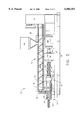
- FIG. 1 is a fragmentary, side elevational view of an injection molding machine having a two-stage electric injection unit according to the present invention.
- FIG. 2 is an enlarged view, partially in section, of the two-stage electric injection unit of the molding machine illustrated in FIG. 1.
- FIG. 3 is a more detailed, enlarged view, of the injection unit illustrated in FIG. 2, focusing on the melt accumulator and mechanical drive elements.
- the present invention relates to a two-stage electric injection unit 14 for an injection molding machine; as such, it will be described in the context of a typical machine. Since the general structure and operation of injection molding machines are well known, those aspects of the apparatus which are different or take on a new use with respect to two-stage electric injection will receive primary emphasis.
- the apparatus of the present invention is used in conjunction with an injection molding machine 10, as shown in FIGS. 1 and 2.
- the general configuration of the molding machine 10 includes a conventional clamp unit 12, and a two-stage electric injection unit 14, both of which are mounted on an elongated support or base 16.
- the components of the injection unit 14 are specifically designed to implement electric motor drive technology in a two-stage injection unit.
- the primary elements are an electrically driven extruder 18 and a melt accumulator 20.
- the extruder 18 is intended for continuous plasticizing and, therefore, has a non-reciprocating feed screw 30 (see FIG. 2). If desired, however, the concepts of the present invention can also be applied to a two-stage injection system with a reciprocating feed screw.
- material is supplied to the extruder in any convenient manner, such as by a hopper 24.
- the rotational power for the screw 30 is also provided in a conventional manner, as by an electric motor 26, connected to a speed reduction gearbox 28 that drives the screw 30. Since the movement of the screw 30 is rotational only, the drive system is greatly simplified over the injection units having a screw which must also reciprocate.
- the accumulator 20 is essentially a variable volume reservoir by virtue of a cylindrical barrel 32 containing a plunger 34 that is capable of both rotational and linear movement within the barrel 32. Note that the end of the plunger 34 has a helical flight 36.
- the relative size of the barrel 32 and plunger 34, as well as the stroke of the plunger 34, will vary according to the quantity of melt required to fill the mold. In the constriction of melt accumulator 20, it is desirable to configure the end-shape of the barrel 32 and plunger 34 in a way that minimizes the amount of resin remaining in the barrel 32 when the plunger 34 is fully extended, as will be more fully discussed later.
- the diameter of the plunger 34 dictates the load carrying requirements for the ball screw that converts the rotary motion of the motor into linear motion for the plunger 34.
- the larger shot capacities can be easily accomplished with the two-stage design by providing increased length of stroke at relatively small diameters.
- the disclosed two stage design yields an injection capability of at least 150 oz. at a 2.75 inch diameter plunger 34 that can operate at 20,000 psi with a 5.5 in diameter ball screw; in contrast, prior art all-electric injection molding machines with these design criteria would typically have a shot capacity of only about 30 oz.
- the advantages of the invention are more fully realized when ratio of the full stroke of the plunger 34 to the diameter of the plunger 34 (this criteria is similar to the L/D of a reciprocating screw) is five or higher; the range of ten to fifteen for this ratio is believed to be particularly advantageous.
- This configuration of the accumulator 20 would enable use of commercially available ball screws, while providing a longer stroke (improving shot size accuracy and repeatability) at higher injection pressures.
- the outlet of the extruder 18 connects to accumulator 20 via a suitable conduit 42.
- a ball check valve 46 or other suitable non-return device is provided to control the direction of the flow through conduit 42.
- the check valve 46 prevents a back-flow of melt into the extruder 18 due to the pressure differential.
- the outlet of the accumulator 20 is connected to the injection mold (not shown) via a suitable nozzle 56.
- the plunger 34 of accumulator 20 is preferably actuated by an electromechanical drive assembly 60, see FIGS. 2 and 3.
- the drive assembly 60 preferably includes a ball screw 62, a ball nut 64 with support housing 66, a variable speed electric motor 68 and a motor support 70 that allows for linear movement of the motor 68. More specifically, the ball nut 64 is preferably carried within support housing 66 and is restrained from rotation by its attachment to housing 66 through suitable means, such as a load cell 76.
- the driven end of the ball screw 62 connects to the motor shaft 78; the opposite end of the screw 62 connects to the plunger 34 of the accumulator 20 by means of a coupling 72.
- the coupling 72 includes a one-way clutch 86 that allows the ball screw 62 to rotate freely with respect to the plunger 34 during injection (clockwise rotation of screw 62) to transmit efficiently linear (horizontal) force from the ball screw 62 to the plunger 34 without adversely affecting the melt contained in the accumulator 20.
- reverse (counter-clockwise) rotation of the ball screw 62 engages the one-way clutch 86 causing the plunger 34 to rotate within the cylinder 32.
- the support 70 for the motor 68 is configured to provide stability for the motor 68 while allowing it to move linearly in a direction parallel to the movement of the plunger 34, as indicated by arrow A.
- connection of motor shaft 78 to ball screw 62 could be accomplished via an elongated spline coupling, allowing a stationary mounting of the motor 68 at a position more rearward from that shown.
- a cycle of operation of the injection molding machine 10, incorporating the two-stage injection unit 14 of the present invention will now be described.
- the feed screw 30 is rotated within barrel 38 by the extruder motor 26 to begin plastication of the material that will be supplied as plastic melt to the accumulator 20.
- the rotation of the screw 30 builds pressure at the end of the screw 30, moving (opening) the ball check valve 46 and causing material to flow through the conduit 42 and into the accumulator 20.
- the inlet 40 of accumulator 20 is positioned so that melt flowing into the barrel 32 will pass over the flight 36 at the end of plunger 34.
- the incoming melt will flow along the flight 36, cleaning out melt carried over from the previous shot and moving it toward the outlet end of barrel 32, causing the pressure in the accumulator 20 to build.
- the pressure of the plastic melt reaches a certain level, it will begin to force the plunger 34 rearwardly, thereby moving the ball screw 62 and motor 68 toward the rear of injection unit 14 (support housing 66 remains stationary), see FIG. 3.
- plunger 34 applies a force to ball screw 62 through coupling 72, causing ball screw 62 to move likewise to the rear; as the ball screw 62 moves through ball nut 64 it rotates in a reverse (counter-clockwise) direction. This reverse rotation of the ball screw 62 is imparted to the plunger 34 via engagement of the one-way clutch 86. The rotation of plunger 34 further aids in cleaning carry-over material from the flight 36 by enhancing the wiping action of the inflow of new melt.
- the rate of rearward movement of the plunger 34 can be controlled by the motor 68.
- the motor 68 can be used as a brake to impede the rotation of ball screw 62, which slows the rearward movement of the plunger 34, thereby increasing the back pressure of the plastic melt.
- the motor 68 can be used to speed up the rotation and rearward movement of the ball screw 62, which increases the rate at which the plunger 34 moves back, thereby decreasing the back pressure of the melt. In either case, the rotational speed of the ball screw 62 is imparted to the plunger 34 by clutch 86.
- the extrusion function is complete and rotation of the feed screw 30 is stopped when a sufficient charge of plastic melt is accumulated in front of the plunger 34 in the accumulator 20, as required to fill the cavity of the mold. Concurrently with the extrusion function, the clamp unit 12 has been operated to close and build pressure on the mold that will receive the plastic melt.
- the motor 68 is rotated in a clockwise direction causing the ball screw 62 to advance through ball nut 64 which is constrained by support housing 66.
- the translational (linear) movement of screw 62 is imparted to the plunger 34 housed in the accumulator 20.
- the rotation of the screw 62 is not imparted to the plunger 34 since the one-way clutch 86 is disengaged when the screw 62 rotates in the clockwise direction.
- the motor 68 will also have translational movement (since it is part of the same assembly) along with the ball screw 62 as the plunger 34 is moved linearly in the cylinder 32 of the accumulator 20.
- the forward movement of the plunger 34 causes the accumulated plastic melt to be forced through the nozzle 56 and into the mold cavity.
- the injection pressure generated by movement of the plunger 34 moves the ball check valve 46 to a position that prevents transfer of the melted resin into the extruder 18.
- the injection accumulator 20 initiates pack, then hold, to maintain the proper pressure on the material until the molded part is properly formed.
- the injection accumulator 20 reaches the "hold" portion of the cycle, it has emptied itself of material.
- the injection of plastic melt is accomplished by applying sufficient force to move the plunger 34 rapidly forward in the cylinder 32, forcing the melt to flow through the outlet of the injection accumulator 20, on through the nozzle 56, then into the mold.
- This approximate point in the cycle can be identified by the configuration shown in FIG. 2; the plunger 34 in the accumulator 20 is fully forward in the barrel 32, having completed the injection function.
- the pressure held by the injection accumulator 20 is released during mold decompress, which may include a slight retraction of the plunger 34.
- the clamp 12 operates to open the mold, eject the part(s), then re-close to begin a subsequent cycle.
- the injection unit 14 starts rotation of the feed screw 30 to initiate the extrusion function as described previously and begin another cycle of operation.
Landscapes
- Engineering & Computer Science (AREA)
- Manufacturing & Machinery (AREA)
- Mechanical Engineering (AREA)
- Injection Moulding Of Plastics Or The Like (AREA)
- Application Of Or Painting With Fluid Materials (AREA)
Priority Applications (12)
| Application Number | Priority Date | Filing Date | Title |
|---|---|---|---|
| US09/024,731 US6086353A (en) | 1998-02-17 | 1998-02-17 | Two-stage electric injection unit with rotating plunger |
| JP2000531288A JP4383658B2 (ja) | 1998-02-17 | 1998-09-30 | 2段階電気射出ユニット |
| EP98952037A EP1102669B2 (de) | 1998-02-17 | 1998-09-30 | Elektrische zweistufige einspritzeinheit und verfahren zur zuführung von kunststoffschmelze in eine sprizgiessformkavität |
| DE69832536T DE69832536T3 (de) | 1998-02-17 | 1998-09-30 | Elektrische zweistufige einspritzeinheit und verfahren zur zuführung von kunststoffschmelze in eine sprizgiessformkavität |
| PCT/US1998/020784 WO1999041056A1 (en) | 1998-02-17 | 1998-09-30 | Two-stage electric injection unit |
| KR1020007008966A KR100607187B1 (ko) | 1998-02-17 | 1998-09-30 | 2단 전기식 사출 유닛 |
| CN98813644A CN1103669C (zh) | 1998-02-17 | 1998-09-30 | 双级电气注塑装置 |
| BR9815669-1A BR9815669A (pt) | 1998-02-17 | 1998-09-30 | Unidade de injeção elétrica de dois estágios |
| AT98952037T ATE310622T1 (de) | 1998-02-17 | 1998-09-30 | Elektrische zweistufige einspritzeinheit und verfahren zur zuführung von kunststoffschmelze in eine sprizgiessformkavität |
| CA002321036A CA2321036C (en) | 1998-02-17 | 1998-09-30 | Two-stage electric injection unit |
| US09/248,935 US6193499B1 (en) | 1998-02-17 | 1999-02-12 | Electrically operated injection apparatus |
| US09/770,343 US6471904B2 (en) | 1998-02-17 | 2001-01-26 | Method for electrically operated plastics injection |
Applications Claiming Priority (1)
| Application Number | Priority Date | Filing Date | Title |
|---|---|---|---|
| US09/024,731 US6086353A (en) | 1998-02-17 | 1998-02-17 | Two-stage electric injection unit with rotating plunger |
Related Child Applications (1)
| Application Number | Title | Priority Date | Filing Date |
|---|---|---|---|
| US09/248,935 Continuation-In-Part US6193499B1 (en) | 1998-02-17 | 1999-02-12 | Electrically operated injection apparatus |
Publications (1)
| Publication Number | Publication Date |
|---|---|
| US6086353A true US6086353A (en) | 2000-07-11 |
Family
ID=21822113
Family Applications (3)
| Application Number | Title | Priority Date | Filing Date |
|---|---|---|---|
| US09/024,731 Expired - Lifetime US6086353A (en) | 1998-02-17 | 1998-02-17 | Two-stage electric injection unit with rotating plunger |
| US09/248,935 Expired - Lifetime US6193499B1 (en) | 1998-02-17 | 1999-02-12 | Electrically operated injection apparatus |
| US09/770,343 Expired - Lifetime US6471904B2 (en) | 1998-02-17 | 2001-01-26 | Method for electrically operated plastics injection |
Family Applications After (2)
| Application Number | Title | Priority Date | Filing Date |
|---|---|---|---|
| US09/248,935 Expired - Lifetime US6193499B1 (en) | 1998-02-17 | 1999-02-12 | Electrically operated injection apparatus |
| US09/770,343 Expired - Lifetime US6471904B2 (en) | 1998-02-17 | 2001-01-26 | Method for electrically operated plastics injection |
Country Status (10)
| Country | Link |
|---|---|
| US (3) | US6086353A (de) |
| EP (1) | EP1102669B2 (de) |
| JP (1) | JP4383658B2 (de) |
| KR (1) | KR100607187B1 (de) |
| CN (1) | CN1103669C (de) |
| AT (1) | ATE310622T1 (de) |
| BR (1) | BR9815669A (de) |
| CA (1) | CA2321036C (de) |
| DE (1) | DE69832536T3 (de) |
| WO (1) | WO1999041056A1 (de) |
Cited By (12)
| Publication number | Priority date | Publication date | Assignee | Title |
|---|---|---|---|---|
| US6471904B2 (en) * | 1998-02-17 | 2002-10-29 | Uniloy Milacron U.S.A. Inc. | Method for electrically operated plastics injection |
| US20050100624A1 (en) * | 2003-01-21 | 2005-05-12 | Chih-Hao Yang | Rubber extruder |
| US20060093694A1 (en) * | 2004-11-03 | 2006-05-04 | Moog Inc. | Electro-mechanical injection actuator for controllably rotating and translating the feedscrew of a single-stage injection molding machine |
| US20090123587A1 (en) * | 2007-11-09 | 2009-05-14 | American Leistritz Extruder Corp. | Screw extruder with plunger feeder |
| US20090291159A1 (en) * | 2008-05-22 | 2009-11-26 | Good Earth Tools, Inc. | Support Assembly for an Extruder |
| CN1986193B (zh) * | 2005-12-20 | 2010-05-12 | 财团法人工业技术研究院 | 两段式注塑机的注射单元 |
| US20110316179A1 (en) * | 2004-10-08 | 2011-12-29 | Sgl Carbon Ag | Processes for producing a polymer-bonded fiber agglomerate and a fiber-reinforced composite material |
| US20120201921A1 (en) * | 2011-02-09 | 2012-08-09 | Pepsico, Inc. | Extrusion Blow Molding Apparatus For Preparing Polyester Articles |
| US8459348B2 (en) * | 2011-07-27 | 2013-06-11 | Halliburton Energy Services, Inc. | Downhole line tool assembly and method for use thereof |
| US20180085981A1 (en) * | 2016-09-27 | 2018-03-29 | Fanuc Corporation | Injection molding machine |
| US20190152110A1 (en) * | 2014-09-25 | 2019-05-23 | Century Innovation Corporation | Melter and injection apparatus using the same, injection molded product and manufacturing method therefor, and manufacturing method for an inter-member joining body |
| AT527505A1 (de) * | 2023-08-24 | 2025-03-15 | Engel Austria Gmbh | Formgebungsmaschine |
Families Citing this family (20)
| Publication number | Priority date | Publication date | Assignee | Title |
|---|---|---|---|---|
| US6267580B1 (en) * | 1998-11-02 | 2001-07-31 | Murray Incorporated | Micro injection molding machine |
| US6572362B2 (en) | 2001-08-01 | 2003-06-03 | The Goodyear Tire & Rubber Company | Apparatus for injection molding in alternate planes |
| US6604936B2 (en) | 2001-08-01 | 2003-08-12 | The Goodyear Tire & Rubber Company | Apparatus for injection molding |
| JP2008506774A (ja) * | 2004-07-19 | 2008-03-06 | ティア メディカ アクスイェ セルスカプ | タンパク質材料と非酸化性脂肪酸体を含む組成物 |
| US20070035067A1 (en) | 2005-08-09 | 2007-02-15 | Andreas Ujma | Molding machine plasticizing unit sub-assembly and a method of reducing shearing effects in the manufacture of plastic parts |
| DE102007042808B3 (de) * | 2007-09-07 | 2009-04-02 | Kraussmaffei Technologies Gmbh | Spritzeinheit mit kontinuierlich betreibbarer Plastifiziereinheit |
| DE102008027051A1 (de) * | 2008-06-06 | 2009-12-10 | Kraussmaffei Technologies Gmbh | Spritzeinheit |
| CA2741227A1 (en) * | 2008-12-01 | 2010-06-10 | Husky Injection Molding Systems Ltd. | A method of operating a molding system |
| KR101145117B1 (ko) * | 2009-12-25 | 2012-05-14 | 하이티엔 플라스틱스 머시너리 그룹 컴퍼니, 리미티드 | 석재 기반 복합 재료의 사출 성형 방법 및 사출 성형 장치 |
| TWI394648B (zh) * | 2010-07-20 | 2013-05-01 | Haitian plastics machinery group co ltd | 一種以石料為主的複合材料的注射成型方法及注射成型設備 |
| KR101188374B1 (ko) | 2011-02-15 | 2012-10-08 | (주)삼박 | 섬유강화 복합재료의 성형시스템 및 성형방법 |
| US9189329B1 (en) | 2011-10-13 | 2015-11-17 | Marvell International Ltd. | Generating error correcting code (ECC) data using an ECC corresponding to an identified ECC protection level |
| US8959417B2 (en) * | 2011-11-23 | 2015-02-17 | Marvell World Trade Ltd. | Providing low-latency error correcting code capability for memory |
| DE102012101280A1 (de) | 2012-02-17 | 2013-08-22 | Exipnos Ug | Spritzgießcompounder |
| KR101233233B1 (ko) * | 2012-11-07 | 2013-02-14 | 흥화기계공업주식회사 | 바렐형 실리콘 사출성형 장치 |
| KR101246926B1 (ko) * | 2012-11-07 | 2013-03-25 | 흥화기계공업주식회사 | 실리콘 사출성형용 정량공급 장치 |
| CN109228198B (zh) * | 2018-10-08 | 2020-12-01 | 滁州市协众家电配件有限公司 | 一种洗衣机配件生产用注塑装置 |
| CN112848160A (zh) * | 2021-03-11 | 2021-05-28 | 苏州锦珂塑胶科技有限公司 | 油电混动注塑机 |
| CN113524558A (zh) * | 2021-07-08 | 2021-10-22 | 嘉善川田环保科技有限公司 | 一种利用压注原理制造塑料产品的装置 |
| CN117901333B (zh) * | 2023-05-05 | 2024-08-06 | 中南大学 | 一种用于超声塑化微注塑机的注射机构及控制方法 |
Citations (9)
| Publication number | Priority date | Publication date | Assignee | Title |
|---|---|---|---|---|
| US3861841A (en) * | 1971-06-14 | 1975-01-21 | Robert Hanning | Machine for the injection molding of a mixture of plasticized synthetic material |
| US4290701A (en) * | 1979-07-06 | 1981-09-22 | Husky Injection Molding Systems Inc. | Injection-molding machine with reciprocating plasticizing screw |
| US4722679A (en) * | 1986-06-13 | 1988-02-02 | Tri-Delta Technology, Inc. | Injection molding machine |
| US4734243A (en) * | 1985-07-25 | 1988-03-29 | Aisin Seiki Kabushiki Kaisha | Injection molding machine and method |
| US4758391A (en) * | 1984-07-24 | 1988-07-19 | Nissei Plastics Industrial Co. Ltd. | Method for controlling back pressure in electrically-operated injection apparatus |
| US5281384A (en) * | 1992-06-15 | 1994-01-25 | Western Container Corporation | Improved method for transfer of molding material in two stage injection molding units during molding of preforms |
| US5454995A (en) * | 1994-04-18 | 1995-10-03 | Cincinnati Milacron, Inc. | Method for reducing cycle time in an injection molding machine |
| US5606707A (en) * | 1994-09-30 | 1997-02-25 | Martin Marietta Corporation | Real-time image processor |
| US5863567A (en) * | 1997-07-28 | 1999-01-26 | Cincinnati Milacron Inc. | Two-stage electric injection unit for a molding machine |
Family Cites Families (15)
| Publication number | Priority date | Publication date | Assignee | Title |
|---|---|---|---|---|
| US4557683A (en) * | 1984-05-22 | 1985-12-10 | Usm Corporation | Rotary plasticator ram injection machine |
| US4749536A (en) * | 1986-06-13 | 1988-06-07 | Tri-Delta Technology, Inc. | Injection molding method for filling mold and maintaining pressure |
| KR920008771B1 (ko) * | 1988-10-13 | 1992-10-09 | 세이끼 코포레이션 컴파니, 티미티드 | 사출성형 방법 및 장치 |
| US5286187A (en) * | 1988-12-20 | 1994-02-15 | Mitsui Petrochemical Co., Ltd. | Method for molding saturated crystalline polyesters and molding equipment therefor |
| JPH04126217A (ja) * | 1990-09-17 | 1992-04-27 | Nissei Plastics Ind Co | 合成樹脂材料の射出方法 |
| JPH07106586B2 (ja) * | 1992-04-30 | 1995-11-15 | ビーエイチ工業有限会社 | 複合樹脂の混練射出成形方法およびその装置 |
| DE4344335C2 (de) † | 1993-12-23 | 1996-02-01 | Krauss Maffei Ag | Einspritzaggregat für eine Spritzgießmaschine |
| CN1071181C (zh) * | 1995-08-23 | 2001-09-19 | 埃特灵格塑料机械股份有限公司 | 具有联合加热通道系统的注塑机 |
| JPH09123241A (ja) * | 1995-10-27 | 1997-05-13 | Sodick Co Ltd | スクリュプリプラ式射出成形装置の射出制御方法 |
| US5645868A (en) * | 1995-11-17 | 1997-07-08 | Cincinnati Milacron Inc. | Drive apparatus for an injection unit |
| AT404996B (de) † | 1995-12-27 | 1999-04-26 | Engel Gmbh Maschbau | Verfahren zum betreiben eines antriebes |
| JP3066521B2 (ja) † | 1996-04-30 | 2000-07-17 | 日精樹脂工業株式会社 | プリプラ式射出成形機の制御方法 |
| DE69706167T2 (de) † | 1996-05-13 | 2002-05-02 | Matsushita Electric Industrial Co., Ltd. | Einspritzvorrichtung |
| US6086353A (en) * | 1998-02-17 | 2000-07-11 | Cincinnati Milacron Inc. | Two-stage electric injection unit with rotating plunger |
| US6200127B1 (en) * | 1999-02-26 | 2001-03-13 | Milacron Inc. | Bi-directional check ring for a two-stage injection unit |
-
1998
- 1998-02-17 US US09/024,731 patent/US6086353A/en not_active Expired - Lifetime
- 1998-09-30 KR KR1020007008966A patent/KR100607187B1/ko not_active Expired - Lifetime
- 1998-09-30 WO PCT/US1998/020784 patent/WO1999041056A1/en not_active Ceased
- 1998-09-30 CA CA002321036A patent/CA2321036C/en not_active Expired - Fee Related
- 1998-09-30 DE DE69832536T patent/DE69832536T3/de not_active Expired - Lifetime
- 1998-09-30 BR BR9815669-1A patent/BR9815669A/pt active Search and Examination
- 1998-09-30 EP EP98952037A patent/EP1102669B2/de not_active Expired - Lifetime
- 1998-09-30 AT AT98952037T patent/ATE310622T1/de not_active IP Right Cessation
- 1998-09-30 JP JP2000531288A patent/JP4383658B2/ja not_active Expired - Lifetime
- 1998-09-30 CN CN98813644A patent/CN1103669C/zh not_active Expired - Lifetime
-
1999
- 1999-02-12 US US09/248,935 patent/US6193499B1/en not_active Expired - Lifetime
-
2001
- 2001-01-26 US US09/770,343 patent/US6471904B2/en not_active Expired - Lifetime
Patent Citations (9)
| Publication number | Priority date | Publication date | Assignee | Title |
|---|---|---|---|---|
| US3861841A (en) * | 1971-06-14 | 1975-01-21 | Robert Hanning | Machine for the injection molding of a mixture of plasticized synthetic material |
| US4290701A (en) * | 1979-07-06 | 1981-09-22 | Husky Injection Molding Systems Inc. | Injection-molding machine with reciprocating plasticizing screw |
| US4758391A (en) * | 1984-07-24 | 1988-07-19 | Nissei Plastics Industrial Co. Ltd. | Method for controlling back pressure in electrically-operated injection apparatus |
| US4734243A (en) * | 1985-07-25 | 1988-03-29 | Aisin Seiki Kabushiki Kaisha | Injection molding machine and method |
| US4722679A (en) * | 1986-06-13 | 1988-02-02 | Tri-Delta Technology, Inc. | Injection molding machine |
| US5281384A (en) * | 1992-06-15 | 1994-01-25 | Western Container Corporation | Improved method for transfer of molding material in two stage injection molding units during molding of preforms |
| US5454995A (en) * | 1994-04-18 | 1995-10-03 | Cincinnati Milacron, Inc. | Method for reducing cycle time in an injection molding machine |
| US5606707A (en) * | 1994-09-30 | 1997-02-25 | Martin Marietta Corporation | Real-time image processor |
| US5863567A (en) * | 1997-07-28 | 1999-01-26 | Cincinnati Milacron Inc. | Two-stage electric injection unit for a molding machine |
Cited By (19)
| Publication number | Priority date | Publication date | Assignee | Title |
|---|---|---|---|---|
| US6471904B2 (en) * | 1998-02-17 | 2002-10-29 | Uniloy Milacron U.S.A. Inc. | Method for electrically operated plastics injection |
| US20050100624A1 (en) * | 2003-01-21 | 2005-05-12 | Chih-Hao Yang | Rubber extruder |
| US7004741B2 (en) * | 2003-01-21 | 2006-02-28 | Multiple Corporation | Rubber extruder |
| US20110316179A1 (en) * | 2004-10-08 | 2011-12-29 | Sgl Carbon Ag | Processes for producing a polymer-bonded fiber agglomerate and a fiber-reinforced composite material |
| US8603374B2 (en) * | 2004-10-08 | 2013-12-10 | Sgl Carbon Se | Processes for producing a polymer-bonded fiber agglomerate and a fiber-reinforced composite material |
| US20060093694A1 (en) * | 2004-11-03 | 2006-05-04 | Moog Inc. | Electro-mechanical injection actuator for controllably rotating and translating the feedscrew of a single-stage injection molding machine |
| CN1986193B (zh) * | 2005-12-20 | 2010-05-12 | 财团法人工业技术研究院 | 两段式注塑机的注射单元 |
| US20090123587A1 (en) * | 2007-11-09 | 2009-05-14 | American Leistritz Extruder Corp. | Screw extruder with plunger feeder |
| US7954991B2 (en) | 2007-11-09 | 2011-06-07 | Leistritz Extrusionstechnik Gmbh | Screw extruder with plunger feeder |
| US8137092B2 (en) | 2008-05-22 | 2012-03-20 | Edward Williams | Support assembly for an extruder |
| US20090291159A1 (en) * | 2008-05-22 | 2009-11-26 | Good Earth Tools, Inc. | Support Assembly for an Extruder |
| US20120201921A1 (en) * | 2011-02-09 | 2012-08-09 | Pepsico, Inc. | Extrusion Blow Molding Apparatus For Preparing Polyester Articles |
| US8556621B2 (en) * | 2011-02-09 | 2013-10-15 | Pepsico, Inc. | Extrusion blow molding apparatus for preparing polyester articles |
| US8459348B2 (en) * | 2011-07-27 | 2013-06-11 | Halliburton Energy Services, Inc. | Downhole line tool assembly and method for use thereof |
| US20190152110A1 (en) * | 2014-09-25 | 2019-05-23 | Century Innovation Corporation | Melter and injection apparatus using the same, injection molded product and manufacturing method therefor, and manufacturing method for an inter-member joining body |
| US20180085981A1 (en) * | 2016-09-27 | 2018-03-29 | Fanuc Corporation | Injection molding machine |
| US11524433B2 (en) * | 2016-09-27 | 2022-12-13 | Fanuc Corporation | Injection molding machine |
| AT527505A1 (de) * | 2023-08-24 | 2025-03-15 | Engel Austria Gmbh | Formgebungsmaschine |
| AT527505B1 (de) * | 2023-08-24 | 2025-06-15 | Engel Austria Gmbh | Formgebungsmaschine |
Also Published As
| Publication number | Publication date |
|---|---|
| KR20010040978A (ko) | 2001-05-15 |
| JP2002502732A (ja) | 2002-01-29 |
| US6193499B1 (en) | 2001-02-27 |
| BR9815669A (pt) | 2000-11-14 |
| EP1102669B1 (de) | 2005-11-23 |
| CA2321036C (en) | 2004-01-13 |
| US6471904B2 (en) | 2002-10-29 |
| DE69832536D1 (de) | 2005-12-29 |
| WO1999041056A1 (en) | 1999-08-19 |
| DE69832536T3 (de) | 2011-06-22 |
| KR100607187B1 (ko) | 2006-08-01 |
| ATE310622T1 (de) | 2005-12-15 |
| EP1102669A1 (de) | 2001-05-30 |
| CN1284909A (zh) | 2001-02-21 |
| CA2321036A1 (en) | 1999-08-19 |
| EP1102669A4 (de) | 2002-03-27 |
| EP1102669B2 (de) | 2010-11-24 |
| CN1103669C (zh) | 2003-03-26 |
| DE69832536T2 (de) | 2006-06-14 |
| US20010005062A1 (en) | 2001-06-28 |
| JP4383658B2 (ja) | 2009-12-16 |
Similar Documents
| Publication | Publication Date | Title |
|---|---|---|
| US6086353A (en) | Two-stage electric injection unit with rotating plunger | |
| US5863567A (en) | Two-stage electric injection unit for a molding machine | |
| CA2405622C (en) | Injection unit for injection molding machines with continuously operating plasticizing unit | |
| US5645868A (en) | Drive apparatus for an injection unit | |
| US20030175380A1 (en) | Drive mechanism, particularly for a closing unit, an injection unit or an ejector of a plastic injection moulding machine | |
| CA2411149C (en) | Energy efficient extruder drive | |
| US20040109917A1 (en) | Energy efficient extruder drive | |
| US6488490B1 (en) | Thermoplastic resin injection molding machine with the injecting unit including a rotary pump and torque limiter | |
| CN1105634C (zh) | 混合式注塑模制机械 | |
| US6120277A (en) | Hybrid injection molding machine | |
| US6200127B1 (en) | Bi-directional check ring for a two-stage injection unit | |
| CA2345949C (en) | Hybrid injection molding machine | |
| US5173312A (en) | Injection unit for plastic injection molding machine |
Legal Events
| Date | Code | Title | Description |
|---|---|---|---|
| AS | Assignment |
Owner name: CINCINNATI MILACRON INC., OHIO Free format text: ASSIGNMENT OF ASSIGNORS INTEREST;ASSIGNOR:KLAUS, M. BARR;REEL/FRAME:009492/0937 Effective date: 19980209 |
|
| STCF | Information on status: patent grant |
Free format text: PATENTED CASE |
|
| AS | Assignment |
Owner name: UNILOY MILACRON USA INC., MICHIGAN Free format text: ASSIGNMENT OF ASSIGNORS INTEREST;ASSIGNOR:MILACRON INC.;REEL/FRAME:011887/0236 Effective date: 20000101 |
|
| AS | Assignment |
Owner name: BANKERS TRUST COMPANY, AS ADMINISTRATIVE AGENT, NE Free format text: SECURITY AGREEMENT;ASSIGNORS:VALENITE U.S.A. INC.;MILACRON INC.;TALBOT HOLDINGS, LTD.;AND OTHERS;REEL/FRAME:013110/0122 Effective date: 20011210 |
|
| FEPP | Fee payment procedure |
Free format text: PAYOR NUMBER ASSIGNED (ORIGINAL EVENT CODE: ASPN); ENTITY STATUS OF PATENT OWNER: LARGE ENTITY |
|
| FPAY | Fee payment |
Year of fee payment: 4 |
|
| AS | Assignment |
Owner name: CREDIT SUISSE FIRST BOSTON, ACTING THROUGH ITS CAY Free format text: SECURITY INTEREST;ASSIGNOR:UNILOY MILACRON U.S.A. INC.;REEL/FRAME:014438/0413 Effective date: 20040312 |
|
| AS | Assignment |
Owner name: UNILOY MILACRON U.S.A. INC., OHIO Free format text: RELEASE;ASSIGNOR:DEUTSCHE BANK TRUST COMPANY AMERICAS (F/K/A BANKERS TRUST COMPANY);REEL/FRAME:015209/0817 Effective date: 20040312 |
|
| AS | Assignment |
Owner name: MILACRON INC., OHIO Free format text: CHANGE OF NAME;ASSIGNOR:CINCINNATI MILACRON INC.;REEL/FRAME:014709/0962 Effective date: 19981005 |
|
| AS | Assignment |
Owner name: JP MORGAN CHASE BANK, NEW YORK Free format text: SECURITY AGREEMENT;ASSIGNORS:UNILOY MILACRON INC.;D-M-E U.S.A. INC.;MILACRON INC.;AND OTHERS;REEL/FRAME:014763/0181 Effective date: 20040610 |
|
| AS | Assignment |
Owner name: U.S. BANK NATIONAL ASSOCIATION, OHIO Free format text: SECURITY INTEREST;ASSIGNOR:UNILOY MILACRON U.S.A. INC.;REEL/FRAME:015442/0691 Effective date: 20040610 |
|
| AS | Assignment |
Owner name: D-M-E COMPANY, MICHIGAN Free format text: RELEASE OF LIEN IN PATENTS;ASSIGNOR:CREIDT SUISSE FIRST BOSTON, ACTING THROUGH ITS CAYMAN ISLANDS BRANCH ONE MADISON AVENUE NEW YORK, NY 10010;REEL/FRAME:014852/0375 Effective date: 20040610 Owner name: D-M-E U.S.A. INC., MICHIGAN Free format text: RELEASE OF LIEN IN PATENTS;ASSIGNOR:CREIDT SUISSE FIRST BOSTON, ACTING THROUGH ITS CAYMAN ISLANDS BRANCH ONE MADISON AVENUE NEW YORK, NY 10010;REEL/FRAME:014852/0375 Effective date: 20040610 Owner name: MILACRON INC., OHIO Free format text: RELEASE OF LIEN IN PATENTS;ASSIGNOR:CREIDT SUISSE FIRST BOSTON, ACTING THROUGH ITS CAYMAN ISLANDS BRANCH ONE MADISON AVENUE NEW YORK, NY 10010;REEL/FRAME:014852/0375 Effective date: 20040610 Owner name: MILACRON INDUSTRIAL PRODUCTS, INC., MICHIGAN Free format text: RELEASE OF LIEN IN PATENTS;ASSIGNOR:CREIDT SUISSE FIRST BOSTON, ACTING THROUGH ITS CAYMAN ISLANDS BRANCH ONE MADISON AVENUE NEW YORK, NY 10010;REEL/FRAME:014852/0375 Effective date: 20040610 Owner name: OAK INTERNATIONAL, INC., MICHIGAN Free format text: RELEASE OF LIEN IN PATENTS;ASSIGNOR:CREIDT SUISSE FIRST BOSTON, ACTING THROUGH ITS CAYMAN ISLANDS BRANCH ONE MADISON AVENUE NEW YORK, NY 10010;REEL/FRAME:014852/0375 Effective date: 20040610 Owner name: UNILOY MILACRON U.S.A. INC., MICHIGAN Free format text: RELEASE OF LIEN IN PATENTS;ASSIGNOR:CREIDT SUISSE FIRST BOSTON, ACTING THROUGH ITS CAYMAN ISLANDS BRANCH ONE MADISON AVENUE NEW YORK, NY 10010;REEL/FRAME:014852/0375 Effective date: 20040610 Owner name: UNILOY MILACRON, INC., MICHIGAN Free format text: RELEASE OF LIEN IN PATENTS;ASSIGNOR:CREIDT SUISSE FIRST BOSTON, ACTING THROUGH ITS CAYMAN ISLANDS BRANCH ONE MADISON AVENUE NEW YORK, NY 10010;REEL/FRAME:014852/0375 Effective date: 20040610 |
|
| AS | Assignment |
Owner name: GENERAL ELECTRIC CAPITAL CORPORATION, AS AGENT, CO Free format text: SECURITY AGREEMENT;ASSIGNORS:MILACRON INC.;D-M-E U.S.A. INC.;MILACRON INDUSTRIAL PRODUCTS, INC.;AND OTHERS;REEL/FRAME:018688/0070 Effective date: 20061219 Owner name: GENERAL ELECTRIC CAPITAL CORPORATION, AS AGENT,CON Free format text: SECURITY AGREEMENT;ASSIGNORS:MILACRON INC.;D-M-E U.S.A. INC.;MILACRON INDUSTRIAL PRODUCTS, INC.;AND OTHERS;REEL/FRAME:018688/0070 Effective date: 20061219 Owner name: UNILOY MILACRON INC.,MICHIGAN Free format text: RELEASE BY SECURED PARTY;ASSIGNOR:JPMORGAN CHASE BANK, N.A.;REEL/FRAME:018688/0001 Effective date: 20061219 Owner name: OAK INTERNATIONAL, INC.,MICHIGAN Free format text: RELEASE BY SECURED PARTY;ASSIGNOR:JPMORGAN CHASE BANK, N.A.;REEL/FRAME:018688/0001 Effective date: 20061219 Owner name: MILACRON INDUSTRIAL PRODUCTS, INC.,MICHIGAN Free format text: RELEASE BY SECURED PARTY;ASSIGNOR:JPMORGAN CHASE BANK, N.A.;REEL/FRAME:018688/0001 Effective date: 20061219 Owner name: D-M-E COMPANY,MICHIGAN Free format text: RELEASE BY SECURED PARTY;ASSIGNOR:JPMORGAN CHASE BANK, N.A.;REEL/FRAME:018688/0001 Effective date: 20061219 Owner name: MILACRON INC.,OHIO Free format text: RELEASE BY SECURED PARTY;ASSIGNOR:JPMORGAN CHASE BANK, N.A.;REEL/FRAME:018688/0001 Effective date: 20061219 Owner name: D-M-E U.S.A. INC,MICHIGAN Free format text: RELEASE BY SECURED PARTY;ASSIGNOR:JPMORGAN CHASE BANK, N.A.;REEL/FRAME:018688/0001 Effective date: 20061219 Owner name: UNILOY MILACRON U.S.A. INC.,MICHIGAN Free format text: RELEASE BY SECURED PARTY;ASSIGNOR:JPMORGAN CHASE BANK, N.A.;REEL/FRAME:018688/0001 Effective date: 20061219 Owner name: D-M-E U.S.A. INC, MICHIGAN Free format text: RELEASE BY SECURED PARTY;ASSIGNOR:JPMORGAN CHASE BANK, N.A.;REEL/FRAME:018688/0001 Effective date: 20061219 Owner name: MILACRON INC., OHIO Free format text: RELEASE BY SECURED PARTY;ASSIGNOR:JPMORGAN CHASE BANK, N.A.;REEL/FRAME:018688/0001 Effective date: 20061219 Owner name: MILACRON INDUSTRIAL PRODUCTS, INC., MICHIGAN Free format text: RELEASE BY SECURED PARTY;ASSIGNOR:JPMORGAN CHASE BANK, N.A.;REEL/FRAME:018688/0001 Effective date: 20061219 Owner name: UNILOY MILACRON U.S.A. INC., MICHIGAN Free format text: RELEASE BY SECURED PARTY;ASSIGNOR:JPMORGAN CHASE BANK, N.A.;REEL/FRAME:018688/0001 Effective date: 20061219 Owner name: D-M-E COMPANY, MICHIGAN Free format text: RELEASE BY SECURED PARTY;ASSIGNOR:JPMORGAN CHASE BANK, N.A.;REEL/FRAME:018688/0001 Effective date: 20061219 Owner name: UNILOY MILACRON INC., MICHIGAN Free format text: RELEASE BY SECURED PARTY;ASSIGNOR:JPMORGAN CHASE BANK, N.A.;REEL/FRAME:018688/0001 Effective date: 20061219 Owner name: OAK INTERNATIONAL, INC., MICHIGAN Free format text: RELEASE BY SECURED PARTY;ASSIGNOR:JPMORGAN CHASE BANK, N.A.;REEL/FRAME:018688/0001 Effective date: 20061219 |
|
| FPAY | Fee payment |
Year of fee payment: 8 |
|
| REMI | Maintenance fee reminder mailed | ||
| AS | Assignment |
Owner name: GENERAL ELECTRIC CAPITAL CORPORATION, AS AGENT, CO Free format text: SECURITY AGREEMENT;ASSIGNORS:MILACRON INC;CIMCOOL INDUSTRIAL PRODUCTS INC.;MILACRON MARKETING COMPANY;AND OTHERS;REEL/FRAME:022427/0080 Effective date: 20090311 Owner name: GENERAL ELECTRIC CAPITAL CORPORATION, AS AGENT,CON Free format text: SECURITY AGREEMENT;ASSIGNORS:MILACRON INC;CIMCOOL INDUSTRIAL PRODUCTS INC.;MILACRON MARKETING COMPANY;AND OTHERS;REEL/FRAME:022427/0080 Effective date: 20090311 |
|
| AS | Assignment |
Owner name: MILACRON PLASTICS TECHNOLOGIES GROUP INC., OHIO Free format text: ASSIGNMENT OF ASSIGNORS INTEREST;ASSIGNOR:UNILOY MILACRON USA INC.;REEL/FRAME:022878/0541 Effective date: 20081231 Owner name: MILACRON INC., OHIO Free format text: ASSIGNMENT OF ASSIGNORS INTEREST;ASSIGNOR:MILACRON PLASTIC TECHNOLOGIES GROUP INC.;REEL/FRAME:022878/0553 Effective date: 20081231 |
|
| AS | Assignment |
Owner name: D-M-E COMPANY, INC., MICHIGAN Free format text: RELEASE BY SECURED PARTY;ASSIGNOR:U.S. BANK NATIONAL ASSOCIATION, AS TRUSTEE AND COLLATERAL AGENT;REEL/FRAME:023134/0432 Effective date: 20090821 Owner name: D-M-E U.S.A. INC., MICHIGAN Free format text: RELEASE BY SECURED PARTY;ASSIGNOR:U.S. BANK NATIONAL ASSOCIATION, AS TRUSTEE AND COLLATERAL AGENT;REEL/FRAME:023134/0432 Effective date: 20090821 Owner name: MILACRON INC., OHIO Free format text: RELEASE BY SECURED PARTY;ASSIGNOR:U.S. BANK NATIONAL ASSOCIATION, AS TRUSTEE AND COLLATERAL AGENT;REEL/FRAME:023134/0432 Effective date: 20090821 Owner name: MILACRON INDUSTRIAL PRODUCTS INC., MICHIGAN Free format text: RELEASE BY SECURED PARTY;ASSIGNOR:U.S. BANK NATIONAL ASSOCIATION, AS TRUSTEE AND COLLATERAL AGENT;REEL/FRAME:023134/0432 Effective date: 20090821 Owner name: OAK INTERNATIONAL, INC., MICHIGAN Free format text: RELEASE BY SECURED PARTY;ASSIGNOR:U.S. BANK NATIONAL ASSOCIATION, AS TRUSTEE AND COLLATERAL AGENT;REEL/FRAME:023134/0432 Effective date: 20090821 Owner name: UNILOY MILACRON INC., MICHIGAN Free format text: RELEASE BY SECURED PARTY;ASSIGNOR:U.S. BANK NATIONAL ASSOCIATION, AS TRUSTEE AND COLLATERAL AGENT;REEL/FRAME:023134/0432 Effective date: 20090821 Owner name: UNILOY MILACRON U.S.A. INC., MICHIGAN Free format text: RELEASE BY SECURED PARTY;ASSIGNOR:U.S. BANK NATIONAL ASSOCIATION, AS TRUSTEE AND COLLATERAL AGENT;REEL/FRAME:023134/0432 Effective date: 20090821 Owner name: D-M-E COMPANY, INC.,MICHIGAN Free format text: RELEASE BY SECURED PARTY;ASSIGNOR:U.S. BANK NATIONAL ASSOCIATION, AS TRUSTEE AND COLLATERAL AGENT;REEL/FRAME:023134/0432 Effective date: 20090821 Owner name: D-M-E U.S.A. INC.,MICHIGAN Free format text: RELEASE BY SECURED PARTY;ASSIGNOR:U.S. BANK NATIONAL ASSOCIATION, AS TRUSTEE AND COLLATERAL AGENT;REEL/FRAME:023134/0432 Effective date: 20090821 Owner name: MILACRON INC.,OHIO Free format text: RELEASE BY SECURED PARTY;ASSIGNOR:U.S. BANK NATIONAL ASSOCIATION, AS TRUSTEE AND COLLATERAL AGENT;REEL/FRAME:023134/0432 Effective date: 20090821 Owner name: MILACRON INDUSTRIAL PRODUCTS INC.,MICHIGAN Free format text: RELEASE BY SECURED PARTY;ASSIGNOR:U.S. BANK NATIONAL ASSOCIATION, AS TRUSTEE AND COLLATERAL AGENT;REEL/FRAME:023134/0432 Effective date: 20090821 Owner name: OAK INTERNATIONAL, INC.,MICHIGAN Free format text: RELEASE BY SECURED PARTY;ASSIGNOR:U.S. BANK NATIONAL ASSOCIATION, AS TRUSTEE AND COLLATERAL AGENT;REEL/FRAME:023134/0432 Effective date: 20090821 Owner name: UNILOY MILACRON INC.,MICHIGAN Free format text: RELEASE BY SECURED PARTY;ASSIGNOR:U.S. BANK NATIONAL ASSOCIATION, AS TRUSTEE AND COLLATERAL AGENT;REEL/FRAME:023134/0432 Effective date: 20090821 Owner name: UNILOY MILACRON U.S.A. INC.,MICHIGAN Free format text: RELEASE BY SECURED PARTY;ASSIGNOR:U.S. BANK NATIONAL ASSOCIATION, AS TRUSTEE AND COLLATERAL AGENT;REEL/FRAME:023134/0432 Effective date: 20090821 |
|
| AS | Assignment |
Owner name: WELLS FARGO FOOTHILL, LLC, AS AGENT, GEORGIA Free format text: SECURITY AGREEMENT;ASSIGNORS:MILACRON LLC;DME COMPANY LLC;REEL/FRAME:023134/0669 Effective date: 20090821 Owner name: WELLS FARGO FOOTHILL, LLC, AS AGENT,GEORGIA Free format text: SECURITY AGREEMENT;ASSIGNORS:MILACRON LLC;DME COMPANY LLC;REEL/FRAME:023134/0669 Effective date: 20090821 |
|
| AS | Assignment |
Owner name: MILACRON LLC, OHIO Free format text: ASSIGNMENT OF ASSIGNORS INTEREST;ASSIGNOR:MILACRON INC.;REEL/FRAME:023163/0565 Effective date: 20090818 Owner name: MILACRON LLC,OHIO Free format text: ASSIGNMENT OF ASSIGNORS INTEREST;ASSIGNOR:MILACRON INC.;REEL/FRAME:023163/0565 Effective date: 20090818 |
|
| AS | Assignment |
Owner name: MILACRON INC., OHIO Free format text: RELEASE BY SECURED PARTY;ASSIGNOR:GENERAL ELECTRIC CAPITAL CORPORATION, AS AGENT;REEL/FRAME:023180/0690 Effective date: 20090821 Owner name: MILACRON MARKETING COMPANY, OHIO Free format text: RELEASE BY SECURED PARTY;ASSIGNOR:GENERAL ELECTRIC CAPITAL CORPORATION, AS AGENT;REEL/FRAME:023180/0690 Effective date: 20090821 Owner name: MILACRON PLASTICS TECHNOLOGIES GROUP INC., OHIO Free format text: RELEASE BY SECURED PARTY;ASSIGNOR:GENERAL ELECTRIC CAPITAL CORPORATION, AS AGENT;REEL/FRAME:023180/0690 Effective date: 20090821 Owner name: D-M-E COMPANY, INC., MICHIGAN Free format text: RELEASE BY SECURED PARTY;ASSIGNOR:GENERAL ELECTRIC CAPITAL CORPORATION, AS AGENT;REEL/FRAME:023180/0690 Effective date: 20090821 Owner name: CIMCOOL INDUSTRIAL PRODUCTS INC., OHIO Free format text: RELEASE BY SECURED PARTY;ASSIGNOR:GENERAL ELECTRIC CAPITAL CORPORATION, AS AGENT;REEL/FRAME:023180/0690 Effective date: 20090821 Owner name: MILACRON INC.,OHIO Free format text: RELEASE BY SECURED PARTY;ASSIGNOR:GENERAL ELECTRIC CAPITAL CORPORATION, AS AGENT;REEL/FRAME:023180/0690 Effective date: 20090821 Owner name: MILACRON MARKETING COMPANY,OHIO Free format text: RELEASE BY SECURED PARTY;ASSIGNOR:GENERAL ELECTRIC CAPITAL CORPORATION, AS AGENT;REEL/FRAME:023180/0690 Effective date: 20090821 Owner name: MILACRON PLASTICS TECHNOLOGIES GROUP INC.,OHIO Free format text: RELEASE BY SECURED PARTY;ASSIGNOR:GENERAL ELECTRIC CAPITAL CORPORATION, AS AGENT;REEL/FRAME:023180/0690 Effective date: 20090821 Owner name: D-M-E COMPANY, INC.,MICHIGAN Free format text: RELEASE BY SECURED PARTY;ASSIGNOR:GENERAL ELECTRIC CAPITAL CORPORATION, AS AGENT;REEL/FRAME:023180/0690 Effective date: 20090821 Owner name: CIMCOOL INDUSTRIAL PRODUCTS INC.,OHIO Free format text: RELEASE BY SECURED PARTY;ASSIGNOR:GENERAL ELECTRIC CAPITAL CORPORATION, AS AGENT;REEL/FRAME:023180/0690 Effective date: 20090821 |
|
| AS | Assignment |
Owner name: THE BANK OF NEW YORK MELLON, TEXAS Free format text: SECOND LIEN PATENT SECURITY AGREEMENT;ASSIGNORS:MILACRON LLC;DME COMPANY LLC;REEL/FRAME:023449/0926 Effective date: 20091021 Owner name: THE BANK OF NEW YORK MELLON,TEXAS Free format text: SECOND LIEN PATENT SECURITY AGREEMENT;ASSIGNORS:MILACRON LLC;DME COMPANY LLC;REEL/FRAME:023449/0926 Effective date: 20091021 |
|
| AS | Assignment |
Owner name: MILACRON LLC, OHIO Free format text: SECURITY AGREEMENT;ASSIGNOR:THE BANK OF NEW YORK MELLON;REEL/FRAME:026344/0926 Effective date: 20110506 Owner name: BANK OF AMERICA, N.A., AS ADMINISTRATIVE AGENT, IL Free format text: SECURITY AGREEMENT;ASSIGNORS:MILACRON LLC;DME COMPANY LLC;REEL/FRAME:026341/0357 Effective date: 20110506 |
|
| FPAY | Fee payment |
Year of fee payment: 12 |
|
| AS | Assignment |
Owner name: MILACRON LLC, OHIO Free format text: RELEASE BY SECURED PARTY;ASSIGNOR:WELLS FARGO CAPITAL FINANCE LLC;REEL/FRAME:028130/0164 Effective date: 20120430 |
|
| AS | Assignment |
Owner name: DME COMPANY LLC, MICHIGAN Free format text: PATENT RELEASE;ASSIGNOR:BANK OF AMERICA, N.A., AS ADMINISTRATIVE AGENT;REEL/FRAME:028153/0392 Effective date: 20120430 |
|
| AS | Assignment |
Owner name: U.S. BANK NATIONAL ASSOCIATION, AS NOTES COLLATERA Free format text: SECURITY AGREEMENT;ASSIGNORS:DME COMPANY LLC;MILACRON LLC;REEL/FRAME:028154/0084 Effective date: 20120430 |
|
| AS | Assignment |
Owner name: BANK OF AMERICA, N.A., AS COLLATERAL AGENT, WISCON Free format text: SECURITY AGREEMENT;ASSIGNORS:DME COMPANY LLC;MILACRON LLC;REEL/FRAME:028168/0689 Effective date: 20120430 |
|
| AS | Assignment |
Owner name: U.S. BANK NATIONAL ASSOCIATION, AS NOTES COLLATERA Free format text: SECURITY AGREEMENT;ASSIGNORS:MILACRON LLC;DME COMPANY LLC;REEL/FRAME:030201/0510 Effective date: 20130328 |
|
| AS | Assignment |
Owner name: DME COMPANY LLC, MICHIGAN Free format text: RELEASE OF INTELLECTUAL PROPERTY SECURITY AGREEMENT;ASSIGNOR:U.S. BANK NATIONAL ASSOCIATION;REEL/FRAME:035668/0634 Effective date: 20150514 Owner name: KORTEC, INC., OHIO Free format text: RELEASE OF INTELLECTUAL PROPERTY SECURITY AGREEMENT;ASSIGNOR:U.S. BANK NATIONAL ASSOCIATION;REEL/FRAME:035668/0634 Effective date: 20150514 Owner name: MILACRON LLC, OHIO Free format text: RELEASE OF INTELLECTUAL PROPERTY SECURITY AGREEMENT;ASSIGNOR:U.S. BANK NATIONAL ASSOCIATION;REEL/FRAME:035668/0634 Effective date: 20150514 |
|
| AS | Assignment |
Owner name: JPMORGAN CHASE BANK, N.A., AS COLLATERAL AGENT, IL Free format text: SECURITY AGREEMENT;ASSIGNORS:MILACRON LLC;DME COMPANY LLC, A DELAWARE LIMITED LIABILITY COMPANY;KORTEC, INC., A MASSACHUSETTS CORPORATION;REEL/FRAME:035707/0098 Effective date: 20150514 |
|
| AS | Assignment |
Owner name: MILACRON LLC, OHIO Free format text: RELEASE BY SECURED PARTY;ASSIGNOR:BANK OF AMERICA, N.A.;REEL/FRAME:051094/0964 Effective date: 20191121 Owner name: MILACRON LLC, OHIO Free format text: RELEASE BY SECURED PARTY;ASSIGNOR:JPMORGAN CHASE BANK, N.A.;REEL/FRAME:051094/0944 Effective date: 20191121 Owner name: MILACRON MARKETING COMPANY LLC, OHIO Free format text: RELEASE BY SECURED PARTY;ASSIGNOR:JPMORGAN CHASE BANK, N.A.;REEL/FRAME:051094/0944 Effective date: 20191121 Owner name: DME COMPANY LLC, MICHIGAN Free format text: RELEASE BY SECURED PARTY;ASSIGNOR:JPMORGAN CHASE BANK, N.A.;REEL/FRAME:051094/0944 Effective date: 20191121 Owner name: DME COMPANY LLC, MICHIGAN Free format text: RELEASE BY SECURED PARTY;ASSIGNOR:BANK OF AMERICA, N.A.;REEL/FRAME:051094/0964 Effective date: 20191121 |