US6112850A - Acoustic silencer nozzle - Google Patents
Acoustic silencer nozzle Download PDFInfo
- Publication number
- US6112850A US6112850A US09/390,796 US39079699A US6112850A US 6112850 A US6112850 A US 6112850A US 39079699 A US39079699 A US 39079699A US 6112850 A US6112850 A US 6112850A
- Authority
- US
- United States
- Prior art keywords
- wall section
- exhaust
- fan
- flow path
- exhaust flow
- Prior art date
- Legal status (The legal status is an assumption and is not a legal conclusion. Google has not performed a legal analysis and makes no representation as to the accuracy of the status listed.)
- Expired - Lifetime
Links
Images


Classifications
-
- F—MECHANICAL ENGINEERING; LIGHTING; HEATING; WEAPONS; BLASTING
- F04—POSITIVE - DISPLACEMENT MACHINES FOR LIQUIDS; PUMPS FOR LIQUIDS OR ELASTIC FLUIDS
- F04D—NON-POSITIVE-DISPLACEMENT PUMPS
- F04D29/00—Details, component parts, or accessories
- F04D29/66—Combating cavitation, whirls, noise, vibration or the like; Balancing
- F04D29/661—Combating cavitation, whirls, noise, vibration or the like; Balancing especially adapted for elastic fluid pumps
- F04D29/663—Sound attenuation
-
- F—MECHANICAL ENGINEERING; LIGHTING; HEATING; WEAPONS; BLASTING
- F23—COMBUSTION APPARATUS; COMBUSTION PROCESSES
- F23L—SUPPLYING AIR OR NON-COMBUSTIBLE LIQUIDS OR GASES TO COMBUSTION APPARATUS IN GENERAL ; VALVES OR DAMPERS SPECIALLY ADAPTED FOR CONTROLLING AIR SUPPLY OR DRAUGHT IN COMBUSTION APPARATUS; INDUCING DRAUGHT IN COMBUSTION APPARATUS; TOPS FOR CHIMNEYS OR VENTILATING SHAFTS; TERMINALS FOR FLUES
- F23L17/00—Inducing draught; Tops for chimneys or ventilating shafts; Terminals for flues
- F23L17/005—Inducing draught; Tops for chimneys or ventilating shafts; Terminals for flues using fans
-
- F—MECHANICAL ENGINEERING; LIGHTING; HEATING; WEAPONS; BLASTING
- F23—COMBUSTION APPARATUS; COMBUSTION PROCESSES
- F23L—SUPPLYING AIR OR NON-COMBUSTIBLE LIQUIDS OR GASES TO COMBUSTION APPARATUS IN GENERAL ; VALVES OR DAMPERS SPECIALLY ADAPTED FOR CONTROLLING AIR SUPPLY OR DRAUGHT IN COMBUSTION APPARATUS; INDUCING DRAUGHT IN COMBUSTION APPARATUS; TOPS FOR CHIMNEYS OR VENTILATING SHAFTS; TERMINALS FOR FLUES
- F23L17/00—Inducing draught; Tops for chimneys or ventilating shafts; Terminals for flues
- F23L17/02—Tops for chimneys or ventilating shafts; Terminals for flues
-
- F—MECHANICAL ENGINEERING; LIGHTING; HEATING; WEAPONS; BLASTING
- F23—COMBUSTION APPARATUS; COMBUSTION PROCESSES
- F23J—REMOVAL OR TREATMENT OF COMBUSTION PRODUCTS OR COMBUSTION RESIDUES; FLUES
- F23J2900/00—Special arrangements for conducting or purifying combustion fumes; Treatment of fumes or ashes
- F23J2900/13003—Means for reducing the noise in smoke conducing ducts or systems
-
- F—MECHANICAL ENGINEERING; LIGHTING; HEATING; WEAPONS; BLASTING
- F24—HEATING; RANGES; VENTILATING
- F24F—AIR-CONDITIONING; AIR-HUMIDIFICATION; VENTILATION; USE OF AIR CURRENTS FOR SCREENING
- F24F13/00—Details common to, or for air-conditioning, air-humidification, ventilation or use of air currents for screening
- F24F13/24—Means for preventing or suppressing noise
- F24F2013/245—Means for preventing or suppressing noise using resonance
-
- Y—GENERAL TAGGING OF NEW TECHNOLOGICAL DEVELOPMENTS; GENERAL TAGGING OF CROSS-SECTIONAL TECHNOLOGIES SPANNING OVER SEVERAL SECTIONS OF THE IPC; TECHNICAL SUBJECTS COVERED BY FORMER USPC CROSS-REFERENCE ART COLLECTIONS [XRACs] AND DIGESTS
- Y10—TECHNICAL SUBJECTS COVERED BY FORMER USPC
- Y10S—TECHNICAL SUBJECTS COVERED BY FORMER USPC CROSS-REFERENCE ART COLLECTIONS [XRACs] AND DIGESTS
- Y10S454/00—Ventilation
- Y10S454/906—Noise inhibiting means
Definitions
- the present invention relates in general to nozzles for ventilation fans, and more particularly, to high velocity silencer nozzles for use with exhaust fans.
- Prior art devices have been designed to provide a high velocity jet for exhausting atmosphere and other gases, as described in, for example, U.S. Pat. No. 4,806,076, issued to Andrews, and U.S. Pat. No. 5,439,349, issued to Kupferberg.
- These exhaust fans are typically mounted on the roof areas of buildings and are used to carry exhaust gases as high as possible above the roof line of the building so as to ensure an effective final dilution of the gases within the greatest possible volume of ambient air and their dispersal over a large area with maximum dilution.
- the fan in U.S. Pat. No. 4,806,076 has a nozzle in which two converging flow paths are defined by two respective passageways. The walls forming these passageways are shaped as sectors of conical sections.
- a wind band is provided at one end of the two passages at the outlets thereof to provide an entrainment of fresh air to mix with the gases exhausting from the two passageways.
- the present invention is directed to an acoustic silencer nozzle for apparatus such as ventilation and exhaust fans.
- the nozzle provides at least two converging exhaust paths, each of which extend through an area that is adjacent to any acoustically absorbing media or resonating chambers. In this manner, the noise is reduced at the nozzle or outlet portion and provides a tight plume of high velocity flow.
- the nozzle has at least one opening that allows for ambient atmospheric air to mix with the exhaust gases at the outlet of the nozzle.
- an acoustic silencer nozzle comprises: first and second outer wall sections each approximately shaped as a partial conical section being concave toward each other, or cylindrical or straight on the inner walls, and being oppositely positioned with respect to one another, at least a portion of each of the first and second outer wall sections comprising a perforated material, at least one first upper air outlet and at least one second upper air outlet for releasing exhaust gases therefrom; a first outer sheath disposed adjacent the portion of the first outer wall section comprising the perforated material to define a first outer enclosed space; a second outer sheath disposed adjacent the portion of the second outer wall section comprising the perforated material to define a second outer enclosed space; a first inner wall section positioned in spaced relation with respect to the first outer wall section, the first inner wall section being approximately shaped as a partial conical, cylindrical, or straight section being convex or straight toward the first outer wall section to define at least one first exhaust flow path therebetween adapted to receive exhaust gases and guide
- FIG. 1 is a front plan view of an exemplary acoustic silencer nozzle in accordance with the present invention incorporated into an exhaust fan;
- FIG. 2 is a front cross sectional view of the silencer nozzle of FIG. 1;
- FIG. 3 is a side cross sectional view of the silencer nozzle of FIG. 1 as taken along lines 3--3 in FIG. 1;
- FIG. 4 is a front plan view of exemplary acoustic silencer nozzle in accordance with the present invention showing the usage of a wind band positioned therearound;
- FIG. 5 is a cross sectional view of an exemplary acoustic silencer nozzle of the present invention as shown in FIG. 1 along lines 5--5;
- FIG. 6 is a cross sectional view of an exemplary acoustic silencer nozzle of the present invention as shown in FIG. 1 along lines 6--6;
- FIG. 7 is a front plan view of an alternative embodiment of the acoustic silencer nozzle of the present invention showing a remotely positioned embodiment of a fan drive;
- FIG. 8 is a front elevation of an exemplary acoustic silencer nozzle incorporated into another exhaust fan in accordance with the present invention.
- FIG. 9 is a vertical cross section taken along line 9--9 of FIG. 8;
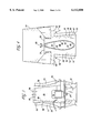
- FIG. 10 is a fragmentary vertical cross section of a detail of the embodiment shown in FIG. 8;
- FIG. 11 is a horizontal cross section taken along line 11--11 of FIG. 10.
- the present invention provides an acoustic silencer nozzle for use with apparatus such as ventilation and exhaust fans.
- the nozzle provides at least two converging exhaust paths, each of which extend through an area that is adjacent acoustically absorbing media or resonating chambers. In this manner, the noise is reduced at the nozzle or outlet portion and provides a tight plume of high velocity flow.
- the nozzle has at least one opening that allows for ambient atmospheric air to mix with the exhaust gases at the outlet of the nozzle.
- An exhaust fan apparatus such as a radial upblast, mixed flow, centrifugal, or axial exhaust fan, includes a main housing 10 having a fan housing 12 in the lower section thereof and acoustic silencer nozzle 18 positioned above the fan housing 12 and extending upwardly therefrom.
- the fan housing 12 defines a fan inlet 14 adapted to receive gases for exhausting thereabove and a fan outlet 16 for allowing movement of the gases upwardly from the fan housing 12 into the acoustic silencer nozzle 18.
- the acoustic silencer nozzle 18 defines a first outer wall section 20 and a second outer wall section 22 being generally conical sections and being concave, cylindrical, or straight with respect to one another.
- the acoustic silencer nozzle 18 further defines a first upper air outlet 24 and a second upper air outlet 26 at the uppermost portion thereof.
- a passive zone section 28 defining a passive zone chamber 48 is located between the first outer wall section 20 and the first upper air outlet 24 and the second outer wall section 22 and the second upper air outlet 26. The passive zone supplies air for mixing by induction into the contaminated air being exhausted through the two upper outlets.
- the passive zone section 28 defines a first inner wall section 30 which is shaped as a conical, cylindrical, or straight section being convex or straight facing outwardly toward the first outer wall section 20.
- a first exhaust flow path 32 is defined between the first inner wall section 30 and the first outer wall section 20.
- the passive zone section 28 defines a second inner wall section 34 which is shaped as a conical section and is convex facing outwardly and in spaced relation with respect to the second outer wall section 22 to define a second exhaust flow path 36 therebetween.
- At least a portion of the first outer wall 20 and the first inner wall 30 comprise a perforated material, such as perforated steel, fiberglass, or polypropylene.
- a perforated material such as perforated steel, fiberglass, or polypropylene.
- the second outer wall 22 and the second inner wall 34 comprise the perforated material.
- First and second outer sheaths 70, 80 are disposed adjacent the section of the outer walls 20, 22 comprising the perforated material.
- the outer sheaths 70, 80 and the perforated sections have respective partitions spaced therebetween thus providing respective outer enclosed spaces or chambers 75, 85.
- the outer enclosed spaces 75, 85 have disposed therein an acoustic absorbing material 77, 87, such as stainless steel wool or a fiberglass material or any acoustically treated media.
- the outer enclosed spaces 75, 85 can each be a resonating chamber.
- the outer enclosed spaces or chambers 75, 85 are closed at either end. As the air travels down the exhaust flow paths 32, 36, noise is absorbed through the perforations in the surfaces of the outer walls 20, 22 into the acoustical fill material 77, 87.
- inner sheaths 90, 95 are disposed adjacent the perforated sections on the inner walls 30, 34, respectively.
- the inner sheaths 90, 95 and the perforated sections have respective partitions spaced therebetween thus providing respective inner enclosed spaces or chambers 92, 97.
- the inner enclosed spaces 92, 97 have disposed therein an acoustic absorbing material 94, 99, such as plastic, coated or galvanized steel, stainless steel, mineral wool, or a fiberglass material or any acoustically treated media, and may also include a chemical resistant wrap or barrier such as mylar, polyurethane, or similar material to prevent exhaust pollutants, moisture, or mold from accumulating in the acoustical material or cavity.
- the inner enclosed spaces 92, 97 can each be a resonating chamber.
- the inner enclosed spaces or chambers 92, 97 are closed at either end. As the air travels down the exhaust flow paths 32, 36, noise is absorbed through the perforations in the surfaces of the inner walls 30, 34 into the acoustical fill material 94, 99.
- the holes in the perforated section constitute about 20 to 75 percent of the area thereof and are approximately 3/32, to 1 inch in diameter, and the perforated section covers at least about 50 to 100 percent of the length of the outer and inner walls.
- a first end wall 38 which may take the form of two end walls 58 may be positioned extending between the first inner wall section 30 and the first outer wall section 20. These end walls as shown in FIGS. 5 and 6 aid in the definition of the first exhaust flow path 32.
- the second end wall 40 which may take the form of two second end walls 60 can be positioned extending from the second inner wall section 34 to the second outer wall section 22 to facilitate defining the second exhaust flow path 36.
- a fan 42 may preferably be positioned within the fan housing 12.
- a fan is operatively connected with respect to a fan drive 54 to control operation thereof.
- the fan drive 54 may be positioned within the passive zone chamber 48 or may be positioned externally from the main housing 10 of the present invention as shown in FIG. 7 or entirely below the nozzle section.
- a belt drive 56 may be included positioned within the passive zone section 28 and may be operatively secured with respect to the drive 54 which itself may be secured with respect to the outer portion of the main housing 10.
- a wind band 44 may be positioned vertically extending in general parallel relationship with respect to the upper end of the acoustic silencer nozzle 18.
- the wind band 44 is located in spaced relation with respect to the outer walls of the acoustic silencer nozzle 18 by a wind band bracket 46.
- air will be induced to flow as shown in FIG. 4 by arrows 62.
- Air will also be induced to flow from the passive zone chamber 48 upwardly as shown by arrow 63 into the contaminated gases being exhausted through the two upper outlets to facilitate mixing therewith.
- ambient air mixes with the exhausting air immediately upon movement of the exhausting gases outwardly through the upper outlets 24 and 26.
- the wind band 44 will protect the vena contracta produced by the converging flow (plume) from the primary exhaust passageway.
- the cross section shown in FIG. 3 is perpendicular through a horizontally extending plane with respect to the cross section shown in FIG. 2.
- the shape of the first exhaust flow path 32 and the second exhaust flow path 36 in FIG. 2 is shown to be parallel and vertically extending inclined inwardly toward the passive zone.
- the view is along lines 3--3 in FIG. 1 and as such the external surface of the first and second end walls 38 and 40 are shown therein. These walls show a configuration with a first intermediate point 50 positioned in the outer wall of first end wall 38 and a second intermediate point 52 positioned in the outer wall of second end wall 40.
- the exemplary apparatus of the present invention can include two or more vertical flow paths and thus two or more upper contaminated air outlets.
- the present invention defines basically one on one side and one on another with a passive zone therebetween. Each of these can be divided into multiple sections such that any number of individual upper flow paths can be defined positioned circumferentially about the passive zone.
- a primary stream of fluid moves at a velocity of at least about 2000 ft/min (with respect to the ambient fluid in the atmosphere), and preferably up to about 6600 ft/min.
- the movement of the primary stream of fluid sets up aspiration in such a manner so that a secondary stream of fluid is drawn from the ambient fluid of the atmosphere.
- the exhaust paths 32, 36 converge in order to keep the exhaust plume tight, which can create a current of air on the order of about 110 feet in diameter moving at about 250 ft/min in still air. This helps to dilute effluent or fumes prior to release into the atmosphere, thus effectively minimizing pollution problems with extremely high efficiency.
- the apparatus 110 has a base 112 meant to be mounted on a roof, a centrifugal fan casing 114 mounted on the base 112, and an inlet duct 116 extending to one side of the casing 114 from the interior of a building (not shown).
- Mounted to the top of the centrifugal fan casing 114 is an exhaust stack or nozzle 118, and topping the exhaust stack is a ring 120 of frusto-conical shape.
- a portion of the inner and outer walls of the stack or nozzle 118 comprise a perforated material, such as perforated steel, fiberglass, or polypropylene.
- First and second outer sheaths 70, 80 are disposed adjacent the section of the outer walls comprising the perforated material.
- the outer sheaths 70, 80 and the perforated sections have respective partitions spaced therebetween thus providing respective outer enclosed spaces or chambers 75, 85.
- the outer enclosed spaces 75, 85 have disposed therein an acoustic absorbing material 77, 87, such as plastic, coated or galvanized steel, stainless steel, mineral wool, or a fiberglass material or any acoustically treated media, and may also include a chemical resistant wrap or barrier such as mylar, polyurethane, or similar material to prevent exhaust pollutants, moisture, or mold from accumulating in the acoustical material or cavity.
- the outer enclosed spaces 75, 85 can each be a resonating chamber.
- the outer enclosed spaces or chambers 75, 85 are closed at either end. As the air travels down the exhaust flow paths, noise is absorbed through the perforations in the surfaces of the outer walls into the acoustical fill material 77, 87.
- inner sheaths 90, 95 are disposed adjacent the perforated sections on the inner walls.
- the inner sheaths 90, 95 and the perforated sections have respective partitions spaced therebetween thus providing respective inner enclosed spaces or chambers 92,97.
- the inner enclosed spaces 92,97 have disposed therein an acoustic absorbing material 94, 99, such as plastic, coated or galvanized steel, stainless steel, mineral wool, or a fiberglass material or any acoustically treated media, and may also include a chemical resistant wrap or barrier such as mylar, polyurethane, or similar material to prevent exhaust pollutants, moisture, or mold from accumulating in the acoustical material or cavity.
- the inner enclosed spaces 92, 97 can each be a resonating chamber.
- the inner enclosed spaces or chambers 92, 97 are closed at either end. As the air travels down the exhaust flow paths, noise is absorbed through the perforations in the surfaces of the inner walls into the acoustical fill material 94, 99.
- the base 112 includes a frame 122 on which a motor 124 is mounted.
- a shaft 126 is journaled in bearing brackets 128 mounted on the frame 122 and extends within the casing 132 in a cantilevered manner.
- the shaft 126 is driven by a drive belt 130 taken off the motor 124.
- shaft 126 mounts a centrifugal impeller 138 having multiple vanes rotating about the axis of the shaft 126.
- the casing 114 includes a scroll 132 surrounding the impeller 138 and interrupted by discharge port 144.
- the scroll 132 includes a cut-off 134 near the discharge port 144.
- the casing 114 also includes parallel side walls 136.
- An inlet port 140 is defined on one side wall 136 of the casing 114, and connector flanges 142 are provided to fasten the inlet port 140 with the inlet duct 116.
- a diffuser tube 146 is mounted to and communicates with the discharge port 144.
- the diffuser tube 146 is in turn connected to the bifurcated duct 148 by means of connecting flanges 149.
- the bifurcated duct 148 includes passageways 150 and 152 which are generally parallel although they, in fact, converge slightly towards the outlet.
- a central opening 155 is formed by means of inner flat walls 154 and 156 defining the passageways 150 and 152 respectively.
- outlet ports 158 and 160 are defined at the upper end of the bifurcated duct 148, communicating with passageways 150 and 152 respectively.
- An annular ring 162 extends about the upper end of the bifurcated duct 148.
- An annulus 164 is formed between the ring 120 and the ring 162.
- the impeller 138 driven by motor 124, will draw the exhaust gases from the building containing airborne contaminants through the duct 116 and then upwardly into the stack or nozzle 118 by first passing through the diffuser and then the double passageways 150 and 152.
- the spent gases exhaust through the outlet ports 158 and 160 at relatively high velocity and cause ambient air to be induced into the annulus 164 to mix with the airborne contaminants and, therefore, dilute the exhaust.
- the present invention provides the advantages of lower stack height and increased safety.
- the present invention minimizes the static pressure loss in the system, and increases attenuation over a typical silencer at the higher velocity.
- the present invention also provides greater accessibility to interior parts (e.g., a motor) for inspection.
- nozzle silencer of the present invention can be used with any type of outlet.
- the fan, motor, and drive can be located anywhere.
- the present invention can be used with fans of various types or other such apparatus that emit an exhaust at a velocity of over about 2000 ft/min.
Landscapes
- Engineering & Computer Science (AREA)
- Mechanical Engineering (AREA)
- General Engineering & Computer Science (AREA)
- Chemical & Material Sciences (AREA)
- Combustion & Propulsion (AREA)
- Structures Of Non-Positive Displacement Pumps (AREA)
- Exhaust Silencers (AREA)
- Cooling Or The Like Of Electrical Apparatus (AREA)
- Jet Pumps And Other Pumps (AREA)
- Percussion Or Vibration Massage (AREA)
- Exhaust Gas After Treatment (AREA)
Priority Applications (9)
| Application Number | Priority Date | Filing Date | Title |
|---|---|---|---|
| US09/390,796 US6112850A (en) | 1999-09-07 | 1999-09-07 | Acoustic silencer nozzle |
| EP00939942A EP1214486B1 (de) | 1999-09-07 | 2000-06-16 | Akustische geräuschdämpferdüse |
| JP2002549043A JP2004515695A (ja) | 1999-09-07 | 2000-06-16 | 消音ノズル |
| ES00939942T ES2260022T3 (es) | 1999-09-07 | 2000-06-16 | Tobera acustica silenciadora. |
| PCT/US2000/016651 WO2001018324A1 (en) | 1999-09-07 | 2000-06-16 | Acoustic silencer nozzle |
| CA002384505A CA2384505C (en) | 1999-09-07 | 2000-06-16 | Acoustic silencer nozzle |
| CNB008125627A CN1146690C (zh) | 1999-09-07 | 2000-06-16 | 消声喷嘴 |
| AT00939942T ATE321177T1 (de) | 1999-09-07 | 2000-06-16 | Akustische geräuschdämpferdüse |
| DE60026837T DE60026837T2 (de) | 1999-09-07 | 2000-06-16 | Akustische geräuschdämpferdüse |
Applications Claiming Priority (1)
| Application Number | Priority Date | Filing Date | Title |
|---|---|---|---|
| US09/390,796 US6112850A (en) | 1999-09-07 | 1999-09-07 | Acoustic silencer nozzle |
Publications (1)
| Publication Number | Publication Date |
|---|---|
| US6112850A true US6112850A (en) | 2000-09-05 |
Family
ID=23543975
Family Applications (1)
| Application Number | Title | Priority Date | Filing Date |
|---|---|---|---|
| US09/390,796 Expired - Lifetime US6112850A (en) | 1999-09-07 | 1999-09-07 | Acoustic silencer nozzle |
Country Status (9)
| Country | Link |
|---|---|
| US (1) | US6112850A (de) |
| EP (1) | EP1214486B1 (de) |
| JP (1) | JP2004515695A (de) |
| CN (1) | CN1146690C (de) |
| AT (1) | ATE321177T1 (de) |
| CA (1) | CA2384505C (de) |
| DE (1) | DE60026837T2 (de) |
| ES (1) | ES2260022T3 (de) |
| WO (1) | WO2001018324A1 (de) |
Cited By (30)
| Publication number | Priority date | Publication date | Assignee | Title |
|---|---|---|---|---|
| US6505706B2 (en) | 2001-06-14 | 2003-01-14 | Pratt & Whitney Canada Corp. | Exhaust flow guide for jet noise reduction |
| US6676503B2 (en) | 2001-12-13 | 2004-01-13 | Plasticair Inc. | Exhaust gas nozzle for fan |
| EP1403105A1 (de) * | 2002-09-26 | 2004-03-31 | Peugeot Citroen Automobiles SA | Lüftungseinrichtung eines Kraftfahrzeugs |
| US6896095B2 (en) | 2002-03-26 | 2005-05-24 | Ford Motor Company | Fan shroud with built in noise reduction |
| US20050159102A1 (en) * | 2004-01-20 | 2005-07-21 | Greenheck Fan Corporation | Exhaust fan assembly having flexible coupling |
| US20050159101A1 (en) * | 2004-01-20 | 2005-07-21 | Hrdina Terry L. | Pivotal direct drive motor for exhaust assembly |
| US20050166809A1 (en) * | 2004-01-26 | 2005-08-04 | Richard Sixsmith | Upblast fan nozzle with wind deflecting panels |
| US20050170767A1 (en) * | 2004-01-20 | 2005-08-04 | Greenheck Fan Corporation | Exhaust fan assembly |
| US20050204582A1 (en) * | 2004-01-20 | 2005-09-22 | Rossi Anthony J | Exhaust fan assembly |
| US20060014484A1 (en) * | 2004-07-15 | 2006-01-19 | Greenheck Fan Corporation | Exhaust fan assembly having H-out nozzle |
| US20060060417A1 (en) * | 2004-09-23 | 2006-03-23 | Williams Nicholas A | Auxiliary power unit exhaust duct with muffler incorporating an externally replaceable acoustic liner |
| US20070298700A1 (en) * | 2006-06-21 | 2007-12-27 | Dipti Datta | Exhaust gas stack |
| US20100285730A1 (en) * | 2009-05-11 | 2010-11-11 | Minel Kupferberg | High velocity nozzle and windband assembly |
| US20110053488A1 (en) * | 2008-01-18 | 2011-03-03 | Mpc Inc. | Control system for exhaust gas fan system |
| CN101018947B (zh) * | 2004-01-20 | 2011-09-07 | 格林海克风机股份有限公司 | 排气风扇组合件、相关安装方法及用于其的压力通风系统 |
| WO2012162121A1 (en) * | 2011-05-20 | 2012-11-29 | Dyna-Tech Sales Corporation | Aspirating induction nozzle |
| US20130011239A1 (en) * | 2010-09-03 | 2013-01-10 | Daniel Khalitov | Tubular inline exhaust fan assembly |
| US20130193235A1 (en) * | 2012-02-01 | 2013-08-01 | Brian J. Mornan | Apparatus and Method for Preventing Crosswind Interference in Induction Nozzles |
| US20140286767A1 (en) * | 2013-03-20 | 2014-09-25 | Brian J. Mornan | Variable-Volume Induction Nozzle |
| EP2937643A1 (de) * | 2014-04-01 | 2015-10-28 | Robert Bosch GmbH | Monoblock-Heizungsanlage mit ausgelagertem Lüfter |
| US9371836B2 (en) | 2012-10-25 | 2016-06-21 | Dyna-Tech Sales Corporation | Mixed flow fan assembly |
| US9897111B2 (en) | 2011-05-20 | 2018-02-20 | Dyna-Tech Sales Corporation | Aspirating induction nozzle with flow transition |
| US10060442B2 (en) | 2013-10-24 | 2018-08-28 | Dyna-Tech Sales Corporation | Mixed flow fan assembly |
| US11035384B2 (en) * | 2018-04-25 | 2021-06-15 | Sonny's Enterprises, Llc | Silencer for an air blower assembly and air blower assembly having the silencer |
| US20210260607A1 (en) * | 2020-02-24 | 2021-08-26 | Altair (UK) Limited | Pulse nozzle for filter cleaning systems |
| US11236914B2 (en) | 2018-01-16 | 2022-02-01 | Plasticair Inc. | Windband silencer with means to reduce cross-wind pressure differential |
| US11561017B2 (en) | 2019-12-09 | 2023-01-24 | Air Distribution Technologies Ip, Llc | Exhaust fan unit of a heating, ventilation, and/or air conditioning (HVAC) system |
| DE102022107468A1 (de) | 2022-03-30 | 2023-10-05 | Vaillant Gmbh | Gebläse für ein Heizgerät, Heizgerät und Verwendung von Metallschaum |
| US20230415172A1 (en) * | 2019-07-01 | 2023-12-28 | Gary C. HAVERDA | Abrasive Blasting Noise Reduction Nozzle and Shroud |
| US20240025016A1 (en) * | 2020-12-02 | 2024-01-25 | Blastone Technology Pty Ltd | Silencer for a blast nozzle |
Families Citing this family (6)
| Publication number | Priority date | Publication date | Assignee | Title |
|---|---|---|---|---|
| JP5276630B2 (ja) * | 2009-10-23 | 2013-08-28 | エア・ウォーター防災株式会社 | ガス消火設備 |
| RU2433314C1 (ru) * | 2010-06-10 | 2011-11-10 | Открытое Акционерное Общество "Научно-производственное объединение гидравлических машин" | Двупоточное отводящее гидравлическое устройство центробежного насоса |
| CN105641841A (zh) * | 2016-01-25 | 2016-06-08 | 维梯埃消防设备(上海)有限公司 | 一种消音装置 |
| US11320159B2 (en) * | 2018-09-19 | 2022-05-03 | Air Distribution Technologies Ip, Llc | Nozzle assembly for exhaust fan unit of HVAC system |
| DE202019101290U1 (de) * | 2019-03-07 | 2020-06-09 | KFB Acoustics Sp. z o.o. | Schalldämpfer |
| DE102020107955A1 (de) | 2020-03-23 | 2021-09-23 | W & S Management Gmbh & Co. Kg | Strahlventilator zur Belüftung von Tunneln, Strahlventilatorsystem und Verfahren |
Citations (27)
| Publication number | Priority date | Publication date | Assignee | Title |
|---|---|---|---|---|
| US3215172A (en) * | 1962-12-24 | 1965-11-02 | Nilsson Robbins & Anderson | Jet engine noise suppressor with shroud for aspiration of air into exhaust stream |
| US3511336A (en) * | 1969-06-10 | 1970-05-12 | Rink Corp | Sound attenuator for air flow |
| US3540547A (en) * | 1968-12-31 | 1970-11-17 | Charles Waddell Coward Jr | Acoustical systems for air moving devices |
| US3572464A (en) * | 1969-10-06 | 1971-03-30 | Rohr Corp | Method and apparatus for suppressing the noise of a fan-jet engine |
| US3575260A (en) * | 1969-05-15 | 1971-04-20 | Rohr Corp | Method and apparatus for augmenting the thrust of a jet-propelled aircraft and suppressing the noise thereof |
| US3591085A (en) * | 1969-07-02 | 1971-07-06 | Rohr Corp | Sound suppressing and thrust reversing apparatus |
| US3605939A (en) * | 1965-07-23 | 1971-09-20 | Bertin & Cie | Device for reducing the noise produced by fluid flow escaping from a nozzle |
| US3611726A (en) * | 1969-09-29 | 1971-10-12 | Rohr Corp | Thrust augmenting and sound suppressing apparatus for a jet engine |
| US3613826A (en) * | 1969-06-30 | 1971-10-19 | Bertin & Cie | System for reducing noise caused by a stream of fluid |
| US3647021A (en) * | 1970-06-22 | 1972-03-07 | Rohr Corp | Sound suppression system |
| US3710890A (en) * | 1971-09-27 | 1973-01-16 | Boeing Co | Aircraft engine noise suppression |
| US3752260A (en) * | 1971-07-15 | 1973-08-14 | Tenneco Inc | Air rush silencer |
| US3949830A (en) * | 1975-06-20 | 1976-04-13 | George Koch Sons, Inc. | Fan silencer |
| US3982605A (en) * | 1975-05-05 | 1976-09-28 | The Carborundum Company | Nozzle noise silencer |
| US4378859A (en) * | 1979-12-13 | 1983-04-05 | Ngk Insulators, Ltd. | Silencer for intake/exhaust gas duct |
| US4418788A (en) * | 1981-04-13 | 1983-12-06 | Mitco Corporation | Branch take-off and silencer for an air distribution system |
| US4422524A (en) * | 1982-03-22 | 1983-12-27 | Lockheed Corporation | Variable shape, fluid flow nozzle for sound suppression |
| US4433751A (en) * | 1981-12-09 | 1984-02-28 | Pratt & Whitney Aircraft Of Canada Limited | Sound suppressor liner |
| US4516657A (en) * | 1982-09-29 | 1985-05-14 | Allard Edward F | Sound suppression of engine noise |
| US4806076A (en) * | 1988-02-22 | 1989-02-21 | Strobic Air Corporation | Radial upblast exhaust fan apparatus |
| US5117939A (en) * | 1989-08-08 | 1992-06-02 | Mitsubishi Electric Home Appliance Co., Ltd. | Sound attenuator |
| US5291672A (en) * | 1992-12-09 | 1994-03-08 | General Electric Company | Sound suppression mixer |
| US5326317A (en) * | 1991-10-18 | 1994-07-05 | Matsushita Seiko Co., Ltd. | Ventilator |
| US5439349A (en) * | 1994-11-15 | 1995-08-08 | Kupferberg; Minel | Exhaust fan apparatus |
| US5513266A (en) * | 1994-04-29 | 1996-04-30 | Digisonix, Inc. | Integral active and passive silencer |
| US5696361A (en) * | 1995-11-13 | 1997-12-09 | Chen; Chia-Hsien | Multi-ducts sound eliminator for air pipe |
| US5717172A (en) * | 1996-10-18 | 1998-02-10 | Northrop Grumman Corporation | Sound suppressor exhaust structure |
Family Cites Families (4)
| Publication number | Priority date | Publication date | Assignee | Title |
|---|---|---|---|---|
| NL262265A (de) * | 1960-03-11 | 1900-01-01 | ||
| GB1166843A (en) * | 1966-04-15 | 1969-10-08 | English Electric Co Ltd | Gas Blower Diffusers |
| DE3830346A1 (de) * | 1988-09-07 | 1990-03-15 | Rehau Ag & Co | Schalldaemmendes luftfuehrungselement |
| FI91995C (fi) * | 1990-11-20 | 1994-09-12 | Valmet Paper Machinery Inc | Absorptiivinen äänenvaimennin, etenkin paperitehtaiden ilmakanaviin |
-
1999
- 1999-09-07 US US09/390,796 patent/US6112850A/en not_active Expired - Lifetime
-
2000
- 2000-06-16 ES ES00939942T patent/ES2260022T3/es not_active Expired - Lifetime
- 2000-06-16 CA CA002384505A patent/CA2384505C/en not_active Expired - Lifetime
- 2000-06-16 DE DE60026837T patent/DE60026837T2/de not_active Expired - Fee Related
- 2000-06-16 CN CNB008125627A patent/CN1146690C/zh not_active Expired - Lifetime
- 2000-06-16 JP JP2002549043A patent/JP2004515695A/ja active Pending
- 2000-06-16 WO PCT/US2000/016651 patent/WO2001018324A1/en not_active Ceased
- 2000-06-16 AT AT00939942T patent/ATE321177T1/de not_active IP Right Cessation
- 2000-06-16 EP EP00939942A patent/EP1214486B1/de not_active Expired - Lifetime
Patent Citations (27)
| Publication number | Priority date | Publication date | Assignee | Title |
|---|---|---|---|---|
| US3215172A (en) * | 1962-12-24 | 1965-11-02 | Nilsson Robbins & Anderson | Jet engine noise suppressor with shroud for aspiration of air into exhaust stream |
| US3605939A (en) * | 1965-07-23 | 1971-09-20 | Bertin & Cie | Device for reducing the noise produced by fluid flow escaping from a nozzle |
| US3540547A (en) * | 1968-12-31 | 1970-11-17 | Charles Waddell Coward Jr | Acoustical systems for air moving devices |
| US3575260A (en) * | 1969-05-15 | 1971-04-20 | Rohr Corp | Method and apparatus for augmenting the thrust of a jet-propelled aircraft and suppressing the noise thereof |
| US3511336A (en) * | 1969-06-10 | 1970-05-12 | Rink Corp | Sound attenuator for air flow |
| US3613826A (en) * | 1969-06-30 | 1971-10-19 | Bertin & Cie | System for reducing noise caused by a stream of fluid |
| US3591085A (en) * | 1969-07-02 | 1971-07-06 | Rohr Corp | Sound suppressing and thrust reversing apparatus |
| US3611726A (en) * | 1969-09-29 | 1971-10-12 | Rohr Corp | Thrust augmenting and sound suppressing apparatus for a jet engine |
| US3572464A (en) * | 1969-10-06 | 1971-03-30 | Rohr Corp | Method and apparatus for suppressing the noise of a fan-jet engine |
| US3647021A (en) * | 1970-06-22 | 1972-03-07 | Rohr Corp | Sound suppression system |
| US3752260A (en) * | 1971-07-15 | 1973-08-14 | Tenneco Inc | Air rush silencer |
| US3710890A (en) * | 1971-09-27 | 1973-01-16 | Boeing Co | Aircraft engine noise suppression |
| US3982605A (en) * | 1975-05-05 | 1976-09-28 | The Carborundum Company | Nozzle noise silencer |
| US3949830A (en) * | 1975-06-20 | 1976-04-13 | George Koch Sons, Inc. | Fan silencer |
| US4378859A (en) * | 1979-12-13 | 1983-04-05 | Ngk Insulators, Ltd. | Silencer for intake/exhaust gas duct |
| US4418788A (en) * | 1981-04-13 | 1983-12-06 | Mitco Corporation | Branch take-off and silencer for an air distribution system |
| US4433751A (en) * | 1981-12-09 | 1984-02-28 | Pratt & Whitney Aircraft Of Canada Limited | Sound suppressor liner |
| US4422524A (en) * | 1982-03-22 | 1983-12-27 | Lockheed Corporation | Variable shape, fluid flow nozzle for sound suppression |
| US4516657A (en) * | 1982-09-29 | 1985-05-14 | Allard Edward F | Sound suppression of engine noise |
| US4806076A (en) * | 1988-02-22 | 1989-02-21 | Strobic Air Corporation | Radial upblast exhaust fan apparatus |
| US5117939A (en) * | 1989-08-08 | 1992-06-02 | Mitsubishi Electric Home Appliance Co., Ltd. | Sound attenuator |
| US5326317A (en) * | 1991-10-18 | 1994-07-05 | Matsushita Seiko Co., Ltd. | Ventilator |
| US5291672A (en) * | 1992-12-09 | 1994-03-08 | General Electric Company | Sound suppression mixer |
| US5513266A (en) * | 1994-04-29 | 1996-04-30 | Digisonix, Inc. | Integral active and passive silencer |
| US5439349A (en) * | 1994-11-15 | 1995-08-08 | Kupferberg; Minel | Exhaust fan apparatus |
| US5696361A (en) * | 1995-11-13 | 1997-12-09 | Chen; Chia-Hsien | Multi-ducts sound eliminator for air pipe |
| US5717172A (en) * | 1996-10-18 | 1998-02-10 | Northrop Grumman Corporation | Sound suppressor exhaust structure |
Cited By (52)
| Publication number | Priority date | Publication date | Assignee | Title |
|---|---|---|---|---|
| US6505706B2 (en) | 2001-06-14 | 2003-01-14 | Pratt & Whitney Canada Corp. | Exhaust flow guide for jet noise reduction |
| US6676503B2 (en) | 2001-12-13 | 2004-01-13 | Plasticair Inc. | Exhaust gas nozzle for fan |
| US6896095B2 (en) | 2002-03-26 | 2005-05-24 | Ford Motor Company | Fan shroud with built in noise reduction |
| EP1403105A1 (de) * | 2002-09-26 | 2004-03-31 | Peugeot Citroen Automobiles SA | Lüftungseinrichtung eines Kraftfahrzeugs |
| FR2845033A1 (fr) * | 2002-09-26 | 2004-04-02 | Peugeot Citroen Automobiles Sa | Dispositif de ventilation d'un vehicule automobile |
| US20050170767A1 (en) * | 2004-01-20 | 2005-08-04 | Greenheck Fan Corporation | Exhaust fan assembly |
| US20050159101A1 (en) * | 2004-01-20 | 2005-07-21 | Hrdina Terry L. | Pivotal direct drive motor for exhaust assembly |
| US7682231B2 (en) | 2004-01-20 | 2010-03-23 | Greenheck Fan Corporation | Exhaust fan assembly |
| US20050204582A1 (en) * | 2004-01-20 | 2005-09-22 | Rossi Anthony J | Exhaust fan assembly |
| US8647182B2 (en) | 2004-01-20 | 2014-02-11 | Greenheck Fan Corporation | Exhaust fan assembly |
| CN101018947B (zh) * | 2004-01-20 | 2011-09-07 | 格林海克风机股份有限公司 | 排气风扇组合件、相关安装方法及用于其的压力通风系统 |
| US9636722B2 (en) | 2004-01-20 | 2017-05-02 | Greenheck Fan Corporation | Exhaust fan assembly |
| US7320636B2 (en) | 2004-01-20 | 2008-01-22 | Greenheck Fan Corporation | Exhaust fan assembly having flexible coupling |
| US20100291849A1 (en) * | 2004-01-20 | 2010-11-18 | Greenheck Fan Corporation | Exhaust Fan Assembly |
| US20050159102A1 (en) * | 2004-01-20 | 2005-07-21 | Greenheck Fan Corporation | Exhaust fan assembly having flexible coupling |
| US20050166809A1 (en) * | 2004-01-26 | 2005-08-04 | Richard Sixsmith | Upblast fan nozzle with wind deflecting panels |
| US7241214B2 (en) * | 2004-01-26 | 2007-07-10 | Plasticair, Inc. | Upblast fan nozzle with wind deflecting panels |
| US20060014484A1 (en) * | 2004-07-15 | 2006-01-19 | Greenheck Fan Corporation | Exhaust fan assembly having H-out nozzle |
| US7547249B2 (en) | 2004-07-15 | 2009-06-16 | Greenheck Fan Corporation | Exhaust fan assembly having H-out nozzle |
| US7350619B2 (en) * | 2004-09-23 | 2008-04-01 | Honeywell International, Inc. | Auxiliary power unit exhaust duct with muffler incorporating an externally replaceable acoustic liner |
| US20060060417A1 (en) * | 2004-09-23 | 2006-03-23 | Williams Nicholas A | Auxiliary power unit exhaust duct with muffler incorporating an externally replaceable acoustic liner |
| US20070298700A1 (en) * | 2006-06-21 | 2007-12-27 | Dipti Datta | Exhaust gas stack |
| US20200363061A1 (en) * | 2008-01-18 | 2020-11-19 | Strobic Air Corporation | Control system for exhaust gas fan system |
| US9423128B2 (en) * | 2008-01-18 | 2016-08-23 | Mpc, Inc. | Control system for exhaust gas fan system |
| US20110053488A1 (en) * | 2008-01-18 | 2011-03-03 | Mpc Inc. | Control system for exhaust gas fan system |
| US12085277B2 (en) * | 2008-01-18 | 2024-09-10 | Strobic Air Corporation | Control system for exhaust gas fan system |
| US10760791B2 (en) | 2008-01-18 | 2020-09-01 | Strobic Air Corporation | Control system for exhaust gas fan system |
| US20100285730A1 (en) * | 2009-05-11 | 2010-11-11 | Minel Kupferberg | High velocity nozzle and windband assembly |
| US8758101B2 (en) * | 2010-09-03 | 2014-06-24 | Twin City Fan Companies, Ltd. | Tubular inline exhaust fan assembly |
| US20130011239A1 (en) * | 2010-09-03 | 2013-01-10 | Daniel Khalitov | Tubular inline exhaust fan assembly |
| EP2612038A4 (de) * | 2010-09-03 | 2018-07-04 | Twin City Fan Companies, Ltd | Röhrenförmige abflussgebläseanordnung |
| US8974272B2 (en) | 2011-05-20 | 2015-03-10 | Dyna-Tech Sales Corporation | Aspirating induction nozzle |
| WO2012162121A1 (en) * | 2011-05-20 | 2012-11-29 | Dyna-Tech Sales Corporation | Aspirating induction nozzle |
| US9897111B2 (en) | 2011-05-20 | 2018-02-20 | Dyna-Tech Sales Corporation | Aspirating induction nozzle with flow transition |
| US9233386B2 (en) * | 2012-02-01 | 2016-01-12 | Dyna-Tech Sales Corporation | Apparatus and method for preventing crosswind interference in induction nozzles |
| US20130193235A1 (en) * | 2012-02-01 | 2013-08-01 | Brian J. Mornan | Apparatus and Method for Preventing Crosswind Interference in Induction Nozzles |
| US9371836B2 (en) | 2012-10-25 | 2016-06-21 | Dyna-Tech Sales Corporation | Mixed flow fan assembly |
| US10036403B2 (en) * | 2013-03-20 | 2018-07-31 | Dyna-Tech Sales Corporation | Variable volume induction nozzle |
| US20140286767A1 (en) * | 2013-03-20 | 2014-09-25 | Brian J. Mornan | Variable-Volume Induction Nozzle |
| US10060442B2 (en) | 2013-10-24 | 2018-08-28 | Dyna-Tech Sales Corporation | Mixed flow fan assembly |
| EP2937643A1 (de) * | 2014-04-01 | 2015-10-28 | Robert Bosch GmbH | Monoblock-Heizungsanlage mit ausgelagertem Lüfter |
| US11236914B2 (en) | 2018-01-16 | 2022-02-01 | Plasticair Inc. | Windband silencer with means to reduce cross-wind pressure differential |
| US11035384B2 (en) * | 2018-04-25 | 2021-06-15 | Sonny's Enterprises, Llc | Silencer for an air blower assembly and air blower assembly having the silencer |
| US20230415172A1 (en) * | 2019-07-01 | 2023-12-28 | Gary C. HAVERDA | Abrasive Blasting Noise Reduction Nozzle and Shroud |
| US12485433B2 (en) * | 2019-07-01 | 2025-12-02 | Gary C. HAVERDA | Abrasive blasting noise reduction nozzle and shroud |
| US11561017B2 (en) | 2019-12-09 | 2023-01-24 | Air Distribution Technologies Ip, Llc | Exhaust fan unit of a heating, ventilation, and/or air conditioning (HVAC) system |
| US20230160585A1 (en) * | 2019-12-09 | 2023-05-25 | Air Distribution Technologies Ip, Llc | Exhaust fan unit of a heating, ventilation, and/or air conditioning (hvac) system |
| US11906201B2 (en) * | 2019-12-09 | 2024-02-20 | Air Distribution Technologies Ip, Llc | Exhaust fan unit of a heating, ventilation, and/or air conditioning (HVAC) system |
| US20210260607A1 (en) * | 2020-02-24 | 2021-08-26 | Altair (UK) Limited | Pulse nozzle for filter cleaning systems |
| US11872576B2 (en) * | 2020-02-24 | 2024-01-16 | Altair (UK) Limited | Pulse nozzle for filter cleaning systems |
| US20240025016A1 (en) * | 2020-12-02 | 2024-01-25 | Blastone Technology Pty Ltd | Silencer for a blast nozzle |
| DE102022107468A1 (de) | 2022-03-30 | 2023-10-05 | Vaillant Gmbh | Gebläse für ein Heizgerät, Heizgerät und Verwendung von Metallschaum |
Also Published As
| Publication number | Publication date |
|---|---|
| DE60026837D1 (de) | 2006-05-11 |
| WO2001018324A1 (en) | 2001-03-15 |
| JP2004515695A (ja) | 2004-05-27 |
| WO2001018324A8 (en) | 2001-10-04 |
| EP1214486B1 (de) | 2006-03-22 |
| DE60026837T2 (de) | 2006-09-28 |
| CN1373825A (zh) | 2002-10-09 |
| ES2260022T3 (es) | 2006-11-01 |
| EP1214486A1 (de) | 2002-06-19 |
| CA2384505C (en) | 2007-09-25 |
| ATE321177T1 (de) | 2006-04-15 |
| CA2384505A1 (en) | 2001-03-15 |
| CN1146690C (zh) | 2004-04-21 |
| EP1214486A4 (de) | 2004-10-13 |
Similar Documents
| Publication | Publication Date | Title |
|---|---|---|
| US6112850A (en) | Acoustic silencer nozzle | |
| US6431974B1 (en) | Acoustic wind band | |
| KR19980031023A (ko) | 팬 입구 유동 제어기 | |
| US20120292407A1 (en) | Aspirating induction nozzle | |
| EP1657451A1 (de) | Kanalgebläse | |
| WO1997018549A1 (en) | Acoustic resonator | |
| CA2456249C (en) | Upblast fan nozzle with wind deflecting panels | |
| WO1997018549A9 (en) | Acoustic resonator | |
| JPH0771389A (ja) | 消音器、エアコンプレッサー組立品及び騒音低減エアコンプレッサー | |
| CN112628597A (zh) | 一种高压消声排气装置 | |
| US20220120457A1 (en) | Windband silencer with means to reduce cross-wind pressure differential | |
| US20130315729A1 (en) | Upblast Exhaust Apparatus With A Variable Outlet Nozzle | |
| JPH0875208A (ja) | 局所排気装置 | |
| KR102022852B1 (ko) | 환풍장치 | |
| HK1051718B (en) | Gas exhaust system | |
| JPH0573296U (ja) | 送風機の吸込騒音防止装置 | |
| JP4482670B2 (ja) | ダクト式消音装置 | |
| KR102299940B1 (ko) | 덕트 조립체 | |
| KR20260021963A (ko) | 소음 저감형 공기정화장치 | |
| FI91320C (fi) | Äänenvaimennin ja menetelmä äänenvaimentimen vaimennusmateriaalin suojaamiseksi | |
| HK1110926A1 (en) | Exhaust fan assembly, method for mounting the same and plenum for the same | |
| JPH08210295A (ja) | 軸流送風機の消音構造 |
Legal Events
| Date | Code | Title | Description |
|---|---|---|---|
| AS | Assignment |
Owner name: MET PRO CORPORATION, PENNSYLVANIA Free format text: ASSIGNMENT OF ASSIGNORS INTEREST;ASSIGNORS:SECREST, LYNN THOMAS;TETLEY, PAUL ANTONY;REEL/FRAME:010773/0277 Effective date: 19990907 |
|
| STCF | Information on status: patent grant |
Free format text: PATENTED CASE |
|
| AS | Assignment |
Owner name: MPC INC., DELAWARE Free format text: ASSIGNMENT OF ASSIGNORS INTEREST;ASSIGNOR:MET-PRO CORPORATION;REEL/FRAME:014146/0001 Effective date: 20030530 |
|
| FPAY | Fee payment |
Year of fee payment: 4 |
|
| CC | Certificate of correction | ||
| FPAY | Fee payment |
Year of fee payment: 8 |
|
| FPAY | Fee payment |
Year of fee payment: 12 |
|
| AS | Assignment |
Owner name: BANK OF AMERICA, N.A., TEXAS Free format text: SECURITY AGREEMENT;ASSIGNOR:MPC INC.;REEL/FRAME:031095/0924 Effective date: 20130827 |
|
| AS | Assignment |
Owner name: STROBIC AIR CORPORATION, PENNSYLVANIA Free format text: ASSIGNMENT OF ASSIGNORS INTEREST;ASSIGNOR:MPC INC.;REEL/FRAME:045388/0497 Effective date: 20180329 |
|
| AS | Assignment |
Owner name: MPC INC., OHIO Free format text: RELEASE BY SECURED PARTY;ASSIGNOR:BANK OF AMERICA, N.A., AS ADMINISTRATIVE AGENT;REEL/FRAME:045401/0923 Effective date: 20180330 |
|
| AS | Assignment |
Owner name: BANK OF MONTREAL, AS ADMINISTRATIVE AGENT, ILLINOIS Free format text: SECURITY INTEREST;ASSIGNOR:STROBIC AIR CORPORATION;REEL/FRAME:045491/0523 Effective date: 20180330 Owner name: BANK OF MONTREAL, AS ADMINISTRATIVE AGENT, ILLINOI Free format text: SECURITY INTEREST;ASSIGNOR:STROBIC AIR CORPORATION;REEL/FRAME:045491/0523 Effective date: 20180330 |