US6129614A - Apparatus for grinding clothing of a textile machine - Google Patents
Apparatus for grinding clothing of a textile machine Download PDFInfo
- Publication number
- US6129614A US6129614A US08/816,775 US81677597A US6129614A US 6129614 A US6129614 A US 6129614A US 81677597 A US81677597 A US 81677597A US 6129614 A US6129614 A US 6129614A
- Authority
- US
- United States
- Prior art keywords
- grinding
- elements
- carding machine
- flats
- grinding apparatus
- Prior art date
- Legal status (The legal status is an assumption and is not a legal conclusion. Google has not performed a legal analysis and makes no representation as to the accuracy of the status listed.)
- Expired - Fee Related
Links
Images


Classifications
-
- D—TEXTILES; PAPER
- D01—NATURAL OR MAN-MADE THREADS OR FIBRES; SPINNING
- D01G—PRELIMINARY TREATMENT OF FIBRES, e.g. FOR SPINNING
- D01G15/00—Carding machines or accessories; Card clothing; Burr-crushing or removing arrangements associated with carding or other preliminary-treatment machines
- D01G15/84—Card clothing; Manufacture thereof not otherwise provided for
-
- B—PERFORMING OPERATIONS; TRANSPORTING
- B24—GRINDING; POLISHING
- B24B—MACHINES, DEVICES, OR PROCESSES FOR GRINDING OR POLISHING; DRESSING OR CONDITIONING OF ABRADING SURFACES; FEEDING OF GRINDING, POLISHING, OR LAPPING AGENTS
- B24B19/00—Single-purpose machines or devices for particular grinding operations not covered by any other main group
- B24B19/16—Single-purpose machines or devices for particular grinding operations not covered by any other main group for grinding sharp-pointed workpieces, e.g. needles, pens, fish hooks, tweezers or record player styli
- B24B19/18—Single-purpose machines or devices for particular grinding operations not covered by any other main group for grinding sharp-pointed workpieces, e.g. needles, pens, fish hooks, tweezers or record player styli for grinding carding equipment, e.g. card-clothings
Definitions
- the present invention concerns the grinding of clothing, in particular but not exclusively, of the clothing of flats of a revolving flat card in a textile machine.
- the invention is applicable to the mounting of a grinding apparatus onto the card, but is not restricted to this application and thus could be applied also to an apparatus to be placed onto a card and carried from card to card as required.
- the concept of the present invention is laid out in such a manner that the apparatus may function on a running card. This point also does not constitute any restriction in the sense that the invention could not be applied to a card at a standstill.
- EP-C-322637 a grinding apparatus has been shown which constantly is in operation, or operable respectively. This apparatus can be applied to grinding the clothing of a flat, and a corresponding embodiment has been shown in FIG. 3 of the EP-C-322637 which in the following will be discussed with reference to FIG. 2 of the present application; a more detailed discussion being dispensed with here.
- the present invention proposes a grinding apparatus characterized in that a plurality of grinding elements is provided, which elements can penetrate between the points of the clothing to be ground, and sweepingly brush the head portions of the points.
- the grinding elements preferably are elastically bendable.
- the grinding elements can be arranged in such a manner that during operation they are distributed over the working width of the card.
- they can be supported on an elongated support member e.g. in such a manner that one end of each grinding element is mounted onto the support member from which it extends at right angles.
- the arrangement can be laid out in such a manner that worn grinding elements (no longer in working order) can be replaced by exchanging the support member.
- the support member can be formed by two half shells e.g. according to the principle explained with reference to the FIGS. 4 and 5 of the DE utility model 94 14 196.
- the grinding apparatus can comprise a support member which during operation can be mounted movably, e.g. rotatably.
- the support member can be mounted onto the card frame during operation using a holding device in a roughly predetermined relation to the revolving flat arrangement, e.g. in such a manner that the clothing of the flats can be ground while they pass through their "return cycle.”
- the grinding elements, the support member and the holding device together can form a unit built into the card e.g. in such a manner that operation of the apparatus is started together with the card start-up.
- the card can comprise a drive, and a control device respectively, for the grinding apparatus.
- the combined unit also could be designed in such a manner that it can be attached to the card, in which case the unit would contain its own drive, and control mechanism respectively.
- FIG. 1 is a copy of the FIG. 1 from the EP Application Nr. 96 101 466 dated Feb. 2, 1996,
- FIG. 2 is a copy of the FIG. 3 from EP-C-322 637,
- FIGS. 3 to 5 are copies of the FIGS. 3 through 5 from the DE Utility Model 94 14 196 mentioned above,
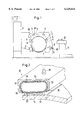
- FIG. 6 is a first embodiment of the present invention in the form of a modification of the arrangement according to the FIGS. 3 to 5,
- FIG. 7 is a schematic view of an individual clothing wire element seen from the front side visualizing the grinding action
- FIG. 8 is a schematic side view of the same individual clothing wire element
- FIG. 9 is a schematic isometric view of a second embodiment, a detail indicated in the FIG. 9 being shown in the FIG. 9A,
- FIG. 10 is a schematic isometric view of a third embodiment, a detail indicated in the FIG. 10 being shown in the FIG. 10A, and
- FIGS. 11 to 13 are further alternative embodiments according to the invention.
- a revolving flat card 1 known as such e.g. the C50 card produced by Maschinenfabrik Rieter AG, is shown schematically.
- the fibre material in the form of opened and cleaned fibre flocks is fed into the feed chute 2, and is taken over by a taker-in or licker-in roll 3 as a feed lap, is transferred to a main drum 4 and is opened further and cleaned by means of a set of revolving flats 5 driven forward or backward, as seen in the direction of the rotation of the drum 4, along a closed loop path over deflecting rolls 6. Fibres from the web located on the main drum 4 then are taken over by a doffer 7 and in a delivery roll arrangement 8 are formed into a card sliver 9.
- a coiler 10 then deposits the card sliver 9 into a can 11 in cycloid manner.
- the set of revolving flats 5 comprises revolving flats not shown individually in the FIG. 1 but indicated in the FIG. 2, and in the FIG. 3 respectively, with the reference sign 13. Each flat 13 is provided with clothing 14.
- the individual flats 13 of the set of revolving flats 5 move "forward" from an entry point E through to an exit point A.
- the carding work is effected during the forward movement.
- the flats are cleaned while passing a cleaning point 60--the cleaning action being explained in more detail in the following with reference to the FIG. 3.
- the clothing 14 on the flats 13 could be ground according to EP C-322 637 as explained with reference to the FIG. 2.
- a grinding device 32 acting onto the flats 13.
- the grinding device 32 comprises a trough type container provided with two side walls 33 and a cover plate 34.
- the free rims 36 of the walls 33 extend parallel to the grinding device extending along the respective flat 13, and at right angles, respectively, to the direction of movement of the clothing 14.
- a support member 37 in the form of a bendable strip extends in longitudinal direction (at right angles of the drawing plane) of the flat 13 over its full length.
- the support member 37 is provided with a grinding coat consisting of e.g. fine grinding particles, in particular of diamond powder.
- the support member 37 can be e.g.
- a thin metallic strip, a fabric or a synthetic material strip provided with an abrasive coat which strip adapts to local unevenness, i.e. to the geometrical shape of the surface defined by the tips of the clothing, without being deformed by the grinding forces. Furthermore, the strip is not to form any creases.
- a hose 38 closed at both ends, made from an elastic material extends inside the trough-shaped container 33, 34 over its full width. Via a valve 39 the hose 38 can be filled with a fluid under a desired pressure. During operation, the hose 38 thus exerts the same pressure at any point along the support member 37. The support member 37 thus is pressed against the cover 13 and thus with its abrasive coat uniformly contacts the clothing 14. As a result, even in the presence of irregularities in the height of the points of the clothing 14, uniform contact of the support member 37 over the full width of the cover 13 is maintained.
- the grinding device shown is only capable of acting upon the outer face areas of the wire points of the flat clothing. Even if conventional grinding devices function in similar manner, their performance proves detrimental for certain types of clothing. Furthermore, the relative movement between the grinding means and the clothing is too slow if the flat movement is relied upon.
- a cleaning device is shown provided with a pivotable device 16 which is irrelevant within the scope of the present invention and thus is not described further here.
- the cleaning device comprises a brush roll 51 rotatable with a predetermined rotational speed and provided with bristles 50 extending on one hand down to the base of the clothing 14 of the flat 13 and on the other hand extend into the pivoting reach 52 (indicated schematically with a dash-dotted circular line) of the pivotable device 16.
- the latter is provided with clothing wires as can be seen from the Figures.
- the bristles are provided in rows, preferentially in a coiled arrangement.
- the brush 51 extends over the full working width. Soon after leaving the device 16, a flat 13 contacts the brush 51 which then effects a second cleaning action.
- a hood 55 encloses a suction area 54.
- a suction duct 56 merges, which (e.g.) can be integrated into a system according to EP-A394 831 and EP-A-583 219 respectively. Dust and fly waste kicked up by the bristles 50 now are sucked into the suction area 54 and are eliminated via the suction duct 56. The suction of course also eliminates any material which falls off from the device 16.
- FIGS. 4 and 5 a preferred design example of the brush 51 is shown which in the following is described in more detail, in which arrangement the brush roll 51 (FIG. 3) is rotated by a shaft 57 via a drive (not shown).
- the drive shaft 57 is supported in bearings (not shown) which are mounted into the side walls 20.
- the drive shaft 57 thus cannot be taken off from its support without an effort.
- the brush 51 is a wear part to be replaced from time to time.
- the brush 51 consists of a sleeve 59 (FIG. 3) and the bristles 50 mentioned before. These bristles are provided on the sleeve 59 and extend radially away therefrom.
- the sleeve 59 is made up by two "half shells" 59A, the end portions of one half shell being shown in a side view in the FIG. 5.
- Each half shell has a cylindrical outer sleeve surface 62 and an inner surface 63, which in its mounted state tightly hugs the shaft 57.
- the two half shells which together form the sleeve 59 are identical as to the structure of the part sleeve 59A as well as to the array of bores 60 (FIG.
- any specific "pair" of such half shells be chosen to make up a brush 51, as any two half shells match as well as any other half shells.
- the bristle arrangements on the two half shells of a brush 51 thus do not represent mutual mirror images but are arranged in such a manner that if the brush 51 is rotated over 180° about the longitudinal axis of the drive shaft 57, the bristles 50 of the one half shell 59A take up the positions previously held by the bristles 50 of the other half shell 59A.
- the half shells 59A each are provided with fastening means in the form of through bores 61.
- Bolts (not shown) can be inserted there through connecting the two half shells to the drive shaft 57.
- the drive shaft for this purpose is provided with two rows of bores (not shown) the inside of each bore being threaded, the bores of these rows being coordinated with the bores 61.
- alternative (preferentially easy to release) fastening means may be provided instead.
- FIG. 6 a first design example according to the present invention is shown designed as a modification of the arrangement illustrated in the FIGS. 3 to 5. Accordingly, a flat bar 13 (including its clothing 14), the sleeve 59 and the bristles 50 (as far as still present) are shown schematically again in the FIG. 6. The direction of movement of the flat bar 13 and the sense of rotation of the sleeve 59 are indicated by arrows.
- the clothing chosen is a flexible or a semi-rigid clothing (compare the above mentioned handbook of textile manufacturing, Volume 2, p.52) in which the individual clothing components 40 are each made from wire (of rectangular or round cross-section) forming a so-called knee 41.
- the bristles 50 penetrate down to the base of the clothing 14, i.e. down to the surface of the flat bar 13 from which the wires protrude, in such a manner that the clothing is cleaned thoroughly.
- only half the circumference of the sleeve 59 is provided with bristles, the other half being provided with grinding elements 42 as will be discussed in more detail in the following with reference to the FIGS. 9 and 10.
- the sleeve 59 in this case serves as a support member for the grinding elements 42 which together with their support member and its holder arrangement form the grinding apparatus according to the present invention.
- the grinding elements in this arrangement resemble the bristles 50 in so far as they are formed as elongated, elastically bendable elements protruding approximately radially from the sleeve surface of the sleeve 59.
- the grinding elements 42 also are more flexible than the wires 40, whereby during rotation of the sleeve and contact of one of these elements with a wire by movement of the element relative to the wire, the grinding element 42 has to yield.
- the elements 42 are substantially shorter than the bristles 50 in such a manner that they can reach the "head portions" only of the clothing wires 40 (above the respective knees 41)--compare also the FIGS. 7 and 8.
- each element 42 still exceeds the speed of the clothing wires 40 in the direction of the flat movement 15. As the grinding elements sweep along the clothing elements 40, they penetrate into the clothing and their free end portions are deflected to both sides of the head portions of the wires 40 (FIG. 7).
- each wire element is ground on its flanks in such a manner that its lateral flanks 43 (FIGS. 7 and 8) converge radially outwards forming an end edge 44.
- these surfaces 43 are subject to a polishing or grinding action.
- the aggressiveness of the polishing or grinding action depends on the design of the grinding elements and on their relative speed of movement. The optimum effectiveness can be determined experimentally for each type of clothing wire.
- the solution described with reference to the FIGS. 6 to 8 presents certain advantages for retrofitting on existing cards.
- the "infrastructure” i.e. the support member in the form of a sleeve 59, its holding device in the form of the drive shaft 57, its bearing arrangement and its corresponding drive arrangement (not shown here) are present already on the existing card.
- the apparatus according to the design example described can be installed easily as just one of the "half shells" according to the FIGS. 4 and 5 is to be provided with grinding elements 42 instead of the bristles 50.
- the flat cleaning device is working continually (as long as the card is in operation), and the clothing wires on the flats thus are ground “continually". But on the other hand certain disadvantages of this solution are to be incurred, however:
- a separate infrastructure is provided on the card, in particular a separate holding device for the support member (on which the grinding elements 42 are mounted) and a separate (and, if required, controllable) drive arrangement.
- a desired speed of the grinding elements relative to the clothing wires exceeding 15 m/s e.g. of 20 m/s
- the grinding point in this arrangement is separated from the cleaning point and preferentially is situated downstream, as seen in the direction 15 of flat movement (FIG. 6), from the cleaning point.
- a control programme is desired for controlling the flat clothing grinding process, a programme of such type can be integrated in the card control system.
- the grinding elements could be moved linearly along the path of the movement of the flat bars 13, an arrangement which could cause problems as it generally is considered undesirable that the grinding elements first impact the free end of a clothing wire. After a grinding movement in a direction in which the grinding elements approaches, and sweeps over, the free end of the clothing wire "from behind", the grinding elements eventually are to be "pulled out” before they are moved back to the starting point of the subsequent grinding movement, which arrangement is complicated and thus cost-intensive.
- a lifting movement also requires relatively ample space within the revolving flat arrangement.
- the support member of the grinding elements preferentially are arranged rotatably in the card, regardless of whether the support member consists of half shells 59A or of a cylindrical sleeve. For simplicity, only the last mentioned possibility is shown in the FIGS. 9 and 10.
- the alternative solution according to the FIG. 9 comprises a coil type array of grinding elements 42 along a cylindrical support member.
- Each element is shaped as a bristle 45 (compare particularly the detail shown in the FIG. 9A).
- the bristles 45 are shorter than the bristles 50 in the arrangement described with reference to the FIG. 6 and the free end of each bristle 45 is coated with an abrasive forming a grinding area (grinding element).
- the coating consists for example of hard particles 46 (grinding particles, diamond particles or similar) secured to the bristle 45 by adhesive.
- the coil-shaped row of elements 42 extends over the full length of the support member and thus over the full working width.
- On the side of the sleeve 59 which is not visible in the FIG. 9 a second row of grinding elements can be arranged forming a mirror image of the first row.
- the alternative design example according to the FIG. 10 also comprises a coil-shaped array of grinding elements 42, which in this case are provided in the form of grinding lamellae 47 (compare particularly the detail shown in the FIG. 10A) which also are coated with an abrasive in the form of hard (grinding) particles.
- the lamellae 47 can be made e.g. from "emery cloth".
- the design example shown partially only in the FIG. 11 corresponds to the alternative design examples according to the FIGS. 9 and 10 in so far as they are made up by coating a base body.
- the base body is formed by a disc 48 both sides of which are coated with hard particles, in which arrangements the disk forms a "grinding wheel".
- the discs can be of annular shape and of a thickness that can vary in radial direction in such manner that they are thinner at the outer edge and thicker at the inner edge.
- the inner portion of each disc can be fastened to a support member (not shown) which is rotatably mounted on the machine.
- the disks 48 are fastened in such a manner that they rotate together with their support member.
- each of the elastically bendable bodies is “profiled", in one case (FIG. 12) by forming longitudinal ribs 49A and by forming transverse ribs 49B.
- the material of which the elements, or the fingers respectively, are made, should be hard in comparison to the metal of the clothing wires to be ground, e.g. steel bristles.
- the description thus far has been based on the assumption that the grinding apparatus should be built into the card.
- the present invention is not restricted in any way to an arrangement of the type mentioned.
- the card could be provided e.g. with mounting points merely to which a support arrangement of the grinding apparatus could be attached.
- the grinding apparatus itself could be moved from card to card and be mounted and operated on a particular card only if required.
- An apparatus of this type could be equipped with its own separate drive arrangement for rotating the support member to which the grinding elements are fastened, or could be provided with a clutch arrangement merely for temporarily establishing a connection with the drive arrangement of the machine.
- the preferred solution comprises a grinding apparatus provided with its own “infrastructure” (support member, drive arrangement, etc.,) and with grinding elements according to the FIG. 9 in which arrangement the support member 59 preferentially is “fully clothed” (instead of being provided with individual coil-shaped remains of grinding element arrangements) i.e. provided with grinding elements covering substantially the whole circumference.
Landscapes
- Engineering & Computer Science (AREA)
- Mechanical Engineering (AREA)
- Textile Engineering (AREA)
- Preliminary Treatment Of Fibers (AREA)
- Treatment Of Fiber Materials (AREA)
- Polishing Bodies And Polishing Tools (AREA)
Applications Claiming Priority (2)
| Application Number | Priority Date | Filing Date | Title |
|---|---|---|---|
| CH93396 | 1996-04-12 | ||
| CH0933/96 | 1996-04-12 |
Publications (1)
| Publication Number | Publication Date |
|---|---|
| US6129614A true US6129614A (en) | 2000-10-10 |
Family
ID=4198549
Family Applications (1)
| Application Number | Title | Priority Date | Filing Date |
|---|---|---|---|
| US08/816,775 Expired - Fee Related US6129614A (en) | 1996-04-12 | 1997-03-18 | Apparatus for grinding clothing of a textile machine |
Country Status (3)
| Country | Link |
|---|---|
| US (1) | US6129614A (de) |
| EP (2) | EP0800895B1 (de) |
| DE (1) | DE59707351D1 (de) |
Cited By (7)
| Publication number | Priority date | Publication date | Assignee | Title |
|---|---|---|---|---|
| US6431969B1 (en) | 1997-10-01 | 2002-08-13 | Maschinenfabrik Rieter Ag | Device for Grinding of Card Clothings |
| US6508698B1 (en) * | 1999-10-11 | 2003-01-21 | Maschinenfabrik Rieter Ag | Grinding or cleaning device for a textile machine |
| US20050034278A1 (en) * | 2003-07-24 | 2005-02-17 | The Indian Card Clothing Co., Ltd. | Revolving flats cleaning brushing & resharpening apparatus in a carding machine |
| US20050107018A1 (en) * | 2003-11-19 | 2005-05-19 | Alain Balmelle | Polishing product element, particularly for finishing optical lenses |
| US20050124268A1 (en) * | 1998-09-09 | 2005-06-09 | Jurg Faas | Device for grinding of clothing in a textile machine |
| CN104047077A (zh) * | 2014-06-15 | 2014-09-17 | 卓郎(金坛)纺织机械有限公司 | 梳棉机活动盖板接头自清洁装置 |
| US11577354B2 (en) * | 2016-11-25 | 2023-02-14 | Araki Manufacturing Co., Ltd. | Method for manufacturing card clothing |
Families Citing this family (4)
| Publication number | Priority date | Publication date | Assignee | Title |
|---|---|---|---|---|
| DE19847236B4 (de) * | 1997-12-13 | 2010-08-26 | TRüTZSCHLER GMBH & CO. KG | Vorrichtung an einer Karde zum Schärfen der Garnitur der Trommel |
| CH693095A5 (de) * | 1997-12-13 | 2003-02-28 | Truetzschler Gmbh & Co Kg | Vorrichtung an einer Karde zum Schärfen der Garnitur der Trommel. |
| DE19908708A1 (de) * | 1998-09-09 | 2000-03-16 | Rieter Ag Maschf | Schärf- bzw. Schleifeinrichtung und Zustelleinrichtung |
| CN106078506A (zh) * | 2016-07-25 | 2016-11-09 | 唐山钢铁集团有限责任公司 | 一种轧辊磨床的轧辊旋转驱动装置 |
Citations (19)
| Publication number | Priority date | Publication date | Assignee | Title |
|---|---|---|---|---|
| DE45171C (de) * | C. A. CHAINEUX & CO. in Aachen, Lothringerstr. 13 | Schleifapparat zur Ausübung des durch das Patent Nr. 14509 geschützten Verfahrens | ||
| DE61636C (de) * | C. A. CAFLISCH in Töfs, Canton Zürich, Schweiz | Vorrichtung zur Führung der wandernden Decken an Krempeln während des Schleifens der Beschläge | ||
| US429044A (en) * | 1890-05-27 | middleton | ||
| GB189522533A (en) * | 1895-11-26 | 1895-12-28 | John Tempest Meats | Improvements in Means or Apparatus for Grinding the Teeth of Revolving Flats in Use in Carding Machines. |
| US1886088A (en) * | 1928-03-03 | 1932-11-01 | Dronsfield James | Apparatus for grinding and treating wire clothed rollers |
| DE606832C (de) * | 1933-06-22 | 1934-12-12 | Joh Jacob Rieter & Cie Ag | Deckelschleifvorrichtung fuer Karden |
| GB490317A (en) * | 1937-04-30 | 1938-08-12 | James Dronsfield | Mechanism or apparatus for needle-pointing or side-grinding the wire on cylinders or doffers of carding engines and such like |
| GB679033A (en) * | 1950-02-10 | 1952-09-10 | Alexander Holdsworth | An improvement in or relating to textile card-grinding machines |
| US2849844A (en) * | 1956-11-26 | 1958-09-02 | Jr Edwin Allen Snape | Card clothing grinding head |
| US3528205A (en) * | 1968-11-27 | 1970-09-15 | Harry M Roberts | Disc grinder for card flats |
| GB2007280A (en) * | 1977-09-13 | 1979-05-16 | Truetzschler & Co | Revolving Card Top and Carding Machine Including such a Card Top |
| JPS57112415A (en) * | 1980-12-29 | 1982-07-13 | Minoru Tanaka | Method of grinding needles on the flat in a comber |
| EP0394831A2 (de) * | 1989-04-26 | 1990-10-31 | Ing. Firma Che Johanson Ab | Vorrichtung zur Herstellung von Formkörpern aus Holz |
| US4984395A (en) * | 1987-12-24 | 1991-01-15 | Rieter Machine Works, Ltd. | Grinding device and method for grinding card clothing |
| JPH03295169A (ja) * | 1990-04-12 | 1991-12-26 | Mitsubishi Heavy Ind Ltd | 固体高分子電解質膜と電極との接合体 |
| EP0565486A1 (de) * | 1992-04-07 | 1993-10-13 | Maschinenfabrik Rieter Ag | Gesteuertes Garniturschleifen |
| EP0583219A1 (de) * | 1992-07-23 | 1994-02-16 | Maschinenfabrik Rieter Ag | Karde oder Putzereimaschine mit einer Absaugvorrichtung |
| DE9414196U1 (de) * | 1994-09-01 | 1995-04-20 | Maschinenfabrik Rieter Ag, Winterthur | Vorrichtung zum Reinigen des Deckelsatzes einer Wanderdeckelkarde |
| EP0787841A1 (de) * | 1996-02-02 | 1997-08-06 | Maschinenfabrik Rieter Ag | Verfahren zur Produktion eines Kardenbandes und Kardiermaschine dazu |
-
1997
- 1997-03-18 US US08/816,775 patent/US6129614A/en not_active Expired - Fee Related
- 1997-03-26 DE DE59707351T patent/DE59707351D1/de not_active Expired - Fee Related
- 1997-03-26 EP EP97810178A patent/EP0800895B1/de not_active Expired - Lifetime
- 1997-03-26 EP EP01109270A patent/EP1122028A3/de not_active Ceased
Patent Citations (20)
| Publication number | Priority date | Publication date | Assignee | Title |
|---|---|---|---|---|
| DE45171C (de) * | C. A. CHAINEUX & CO. in Aachen, Lothringerstr. 13 | Schleifapparat zur Ausübung des durch das Patent Nr. 14509 geschützten Verfahrens | ||
| DE61636C (de) * | C. A. CAFLISCH in Töfs, Canton Zürich, Schweiz | Vorrichtung zur Führung der wandernden Decken an Krempeln während des Schleifens der Beschläge | ||
| US429044A (en) * | 1890-05-27 | middleton | ||
| GB189522533A (en) * | 1895-11-26 | 1895-12-28 | John Tempest Meats | Improvements in Means or Apparatus for Grinding the Teeth of Revolving Flats in Use in Carding Machines. |
| US1886088A (en) * | 1928-03-03 | 1932-11-01 | Dronsfield James | Apparatus for grinding and treating wire clothed rollers |
| DE606832C (de) * | 1933-06-22 | 1934-12-12 | Joh Jacob Rieter & Cie Ag | Deckelschleifvorrichtung fuer Karden |
| GB490317A (en) * | 1937-04-30 | 1938-08-12 | James Dronsfield | Mechanism or apparatus for needle-pointing or side-grinding the wire on cylinders or doffers of carding engines and such like |
| GB679033A (en) * | 1950-02-10 | 1952-09-10 | Alexander Holdsworth | An improvement in or relating to textile card-grinding machines |
| US2849844A (en) * | 1956-11-26 | 1958-09-02 | Jr Edwin Allen Snape | Card clothing grinding head |
| US3528205A (en) * | 1968-11-27 | 1970-09-15 | Harry M Roberts | Disc grinder for card flats |
| GB2007280A (en) * | 1977-09-13 | 1979-05-16 | Truetzschler & Co | Revolving Card Top and Carding Machine Including such a Card Top |
| JPS57112415A (en) * | 1980-12-29 | 1982-07-13 | Minoru Tanaka | Method of grinding needles on the flat in a comber |
| US4984395A (en) * | 1987-12-24 | 1991-01-15 | Rieter Machine Works, Ltd. | Grinding device and method for grinding card clothing |
| EP0322637B1 (de) * | 1987-12-24 | 1991-10-16 | Maschinenfabrik Rieter Ag | Schleifen von Kardengarnituren |
| EP0394831A2 (de) * | 1989-04-26 | 1990-10-31 | Ing. Firma Che Johanson Ab | Vorrichtung zur Herstellung von Formkörpern aus Holz |
| JPH03295169A (ja) * | 1990-04-12 | 1991-12-26 | Mitsubishi Heavy Ind Ltd | 固体高分子電解質膜と電極との接合体 |
| EP0565486A1 (de) * | 1992-04-07 | 1993-10-13 | Maschinenfabrik Rieter Ag | Gesteuertes Garniturschleifen |
| EP0583219A1 (de) * | 1992-07-23 | 1994-02-16 | Maschinenfabrik Rieter Ag | Karde oder Putzereimaschine mit einer Absaugvorrichtung |
| DE9414196U1 (de) * | 1994-09-01 | 1995-04-20 | Maschinenfabrik Rieter Ag, Winterthur | Vorrichtung zum Reinigen des Deckelsatzes einer Wanderdeckelkarde |
| EP0787841A1 (de) * | 1996-02-02 | 1997-08-06 | Maschinenfabrik Rieter Ag | Verfahren zur Produktion eines Kardenbandes und Kardiermaschine dazu |
Non-Patent Citations (1)
| Title |
|---|
| Search Report Dated Aug. 18, 1997 For International Application No. 97810178.0. * |
Cited By (13)
| Publication number | Priority date | Publication date | Assignee | Title |
|---|---|---|---|---|
| US6431969B1 (en) | 1997-10-01 | 2002-08-13 | Maschinenfabrik Rieter Ag | Device for Grinding of Card Clothings |
| US7234997B2 (en) | 1998-09-09 | 2007-06-26 | Maschinenfabrik Rieter, A.G. | Device for grinding of clothing in a textile machine |
| US20050124268A1 (en) * | 1998-09-09 | 2005-06-09 | Jurg Faas | Device for grinding of clothing in a textile machine |
| US20050191943A1 (en) * | 1998-09-09 | 2005-09-01 | Jurg Faas | Device for grinding of clothing in a textile machine |
| US7037181B1 (en) | 1998-09-09 | 2006-05-02 | Maschinenfabrik Rieter Ag | Device for grinding of clothing in a textile machine |
| US7131896B2 (en) | 1998-09-09 | 2006-11-07 | Maschinenfabrik Rieter Ag | Device for grinding of clothing in a textile machine |
| US6508698B1 (en) * | 1999-10-11 | 2003-01-21 | Maschinenfabrik Rieter Ag | Grinding or cleaning device for a textile machine |
| US20050034278A1 (en) * | 2003-07-24 | 2005-02-17 | The Indian Card Clothing Co., Ltd. | Revolving flats cleaning brushing & resharpening apparatus in a carding machine |
| US7082646B2 (en) * | 2003-07-24 | 2006-08-01 | The Indian Card Clothing Co., Ltd. | Revolving flats cleaning brushing and resharpening apparatus in a carding machine |
| US20050107018A1 (en) * | 2003-11-19 | 2005-05-19 | Alain Balmelle | Polishing product element, particularly for finishing optical lenses |
| CN104047077A (zh) * | 2014-06-15 | 2014-09-17 | 卓郎(金坛)纺织机械有限公司 | 梳棉机活动盖板接头自清洁装置 |
| CN104047077B (zh) * | 2014-06-15 | 2018-10-30 | 卓郎(常州)纺织机械有限公司 | 梳棉机活动盖板接头自清洁装置 |
| US11577354B2 (en) * | 2016-11-25 | 2023-02-14 | Araki Manufacturing Co., Ltd. | Method for manufacturing card clothing |
Also Published As
| Publication number | Publication date |
|---|---|
| EP1122028A2 (de) | 2001-08-08 |
| EP0800895A1 (de) | 1997-10-15 |
| DE59707351D1 (de) | 2002-07-04 |
| EP1122028A3 (de) | 2001-12-12 |
| EP0800895B1 (de) | 2002-05-29 |
Similar Documents
| Publication | Publication Date | Title |
|---|---|---|
| US6129614A (en) | Apparatus for grinding clothing of a textile machine | |
| US5526557A (en) | Teaseling and/or fluffing machine for fabric and knitwork with improved suction and cleaning | |
| US6219885B1 (en) | High performance card | |
| US4831691A (en) | Compact carding apparatus with sliver thread-up and method | |
| US5655262A (en) | Apparatus for cleaning fibers | |
| US6431969B1 (en) | Device for Grinding of Card Clothings | |
| US3973359A (en) | Web abrading assembly | |
| EP0329615B1 (de) | Kämmzylinder verwendbar für Kämmaschinen | |
| JPH0348222Y2 (de) | ||
| EP0897032B1 (de) | Verfahren und Vorrichtung zur Oberflächenbehandlung von Textilbahnen mittels beschichteten Drähten | |
| US20020088602A1 (en) | Strip casting apparatus | |
| US7131896B2 (en) | Device for grinding of clothing in a textile machine | |
| US5333357A (en) | Carding machine having a fine-fiber brush | |
| EP1500726B1 (de) | Vorrichtung zum Reinigen, zum Bürsten und zum Schleifen von Wanderdeckeln in Karden | |
| US6052871A (en) | Device and method for cleaning the coverings of the mobile flats in a flat carder | |
| US5989110A (en) | Flexible roll for removing material from components of a fiber processing machine | |
| US6508698B1 (en) | Grinding or cleaning device for a textile machine | |
| US5016321A (en) | Compact carding apparatus with silver thread-up and method | |
| EP1207223A1 (de) | Deckelkard mit Mehrfachzufuhr von Fasern | |
| JPS6015727B2 (ja) | カ−ドに於ける不純物のクリ−ニング装置 | |
| US6119319A (en) | Method and apparatus for surface finishing fabric with coated wires | |
| JPH04228624A (ja) | 繊維材料を案内する装置 | |
| US20020094764A1 (en) | System for guiding and drawing along mobile flats in a flat card | |
| CN212865356U (zh) | 一种面料加工过程灰尘清除装置 | |
| EP1378593A1 (de) | Karde und Kardierverfahren |
Legal Events
| Date | Code | Title | Description |
|---|---|---|---|
| AS | Assignment |
Owner name: MASCHINENFABRIK RIETER AG, SWITZERLAND Free format text: ASSIGNMENT OF ASSIGNORS INTEREST;ASSIGNORS:FAAS, JURG;SAUTER, CHRISTIAN;NAF, BEAT;REEL/FRAME:008724/0475 Effective date: 19970815 |
|
| FEPP | Fee payment procedure |
Free format text: PAYOR NUMBER ASSIGNED (ORIGINAL EVENT CODE: ASPN); ENTITY STATUS OF PATENT OWNER: LARGE ENTITY |
|
| FPAY | Fee payment |
Year of fee payment: 4 |
|
| FPAY | Fee payment |
Year of fee payment: 8 |
|
| REMI | Maintenance fee reminder mailed | ||
| LAPS | Lapse for failure to pay maintenance fees | ||
| STCH | Information on status: patent discontinuation |
Free format text: PATENT EXPIRED DUE TO NONPAYMENT OF MAINTENANCE FEES UNDER 37 CFR 1.362 |
|
| FP | Lapsed due to failure to pay maintenance fee |
Effective date: 20121010 |