US6141599A - Method for setting conveying data for a lead frame - Google Patents
Method for setting conveying data for a lead frame Download PDFInfo
- Publication number
- US6141599A US6141599A US08/892,854 US89285497A US6141599A US 6141599 A US6141599 A US 6141599A US 89285497 A US89285497 A US 89285497A US 6141599 A US6141599 A US 6141599A
- Authority
- US
- United States
- Prior art keywords
- lead frame
- island
- fed
- aligned
- television monitor
- Prior art date
- Legal status (The legal status is an assumption and is not a legal conclusion. Google has not performed a legal analysis and makes no representation as to the accuracy of the status listed.)
- Expired - Fee Related
Links
Images




Classifications
-
- H—ELECTRICITY
- H10—SEMICONDUCTOR DEVICES; ELECTRIC SOLID-STATE DEVICES NOT OTHERWISE PROVIDED FOR
- H10P—GENERIC PROCESSES OR APPARATUS FOR THE MANUFACTURE OR TREATMENT OF DEVICES COVERED BY CLASS H10
- H10P72/00—Handling or holding of wafers, substrates or devices during manufacture or treatment thereof
- H10P72/06—Apparatus for monitoring, sorting, marking, testing or measuring
- H10P72/0606—Position monitoring, e.g. misposition detection or presence detection
-
- H—ELECTRICITY
- H10—SEMICONDUCTOR DEVICES; ELECTRIC SOLID-STATE DEVICES NOT OTHERWISE PROVIDED FOR
- H10P—GENERIC PROCESSES OR APPARATUS FOR THE MANUFACTURE OR TREATMENT OF DEVICES COVERED BY CLASS H10
- H10P72/00—Handling or holding of wafers, substrates or devices during manufacture or treatment thereof
- H10P72/30—Handling or holding of wafers, substrates or devices during manufacture or treatment thereof for conveying, e.g. between different workstations
- H10P72/32—Handling or holding of wafers, substrates or devices during manufacture or treatment thereof for conveying, e.g. between different workstations between different workstations
- H10P72/3212—Handling or holding of wafers, substrates or devices during manufacture or treatment thereof for conveying, e.g. between different workstations between different workstations the substrates to be conveyed not being semiconductor wafers or large planar substrates, e.g. chips or lead frames
-
- Y—GENERAL TAGGING OF NEW TECHNOLOGICAL DEVELOPMENTS; GENERAL TAGGING OF CROSS-SECTIONAL TECHNOLOGIES SPANNING OVER SEVERAL SECTIONS OF THE IPC; TECHNICAL SUBJECTS COVERED BY FORMER USPC CROSS-REFERENCE ART COLLECTIONS [XRACs] AND DIGESTS
- Y10—TECHNICAL SUBJECTS COVERED BY FORMER USPC
- Y10T—TECHNICAL SUBJECTS COVERED BY FORMER US CLASSIFICATION
- Y10T29/00—Metal working
- Y10T29/49—Method of mechanical manufacture
- Y10T29/49002—Electrical device making
- Y10T29/49117—Conductor or circuit manufacturing
- Y10T29/49121—Beam lead frame or beam lead device
Definitions
- the present invention relates to a data setting method in a bonding apparatus and more particularly to a method for setting data which is used to operate a frame feeder for conveying lead frames supplied from a loader side magazine to a bonding position on the bonding stage and then further to an unloader side magazine after the completion of bonding on the lead frames.
- Examples of conventional methods for conveying lead frames in a bonding apparatus such as a wire bonding apparatus, die bonding apparatus, etc. include the methods described in Japanese Patent Application Publication (Kokoku) No. S63-56122 and Japanese Patent Application Laid-Open (Kokai) No. H4-346446.
- Kokoku Japanese Patent Application Publication
- Kokai Japanese Patent Application Laid-Open
- lead frames accommodated inside a loader side magazine are fed out onto the conveying path of a frame feeder by a frame pusher, and a leading end alignment (for aligning a leading end of each lead frame) of the lead frames is performed by a pair of loader side feeding claws, that comprise upper and lower claws, or by positioning pins installed on the claw holder which holds the feeding claws.
- each lead frame is intermittently fed by a distance that is equal to a distance between two devices (islands) provided on the lead frame.
- the lead frame is intermittently fed by a combination of the opening and closing action and reciprocating motion of the feeding claws so that each one of the devices (or islands) is positioned beneath a television camera installed above the bonding position.
- the bonding pattern of the lead frame is detected by the television camera; and after a correction of any positional deviation, bonding is performed by the bonding apparatus.
- the lead frame is moved one pitch by the feeding claws, so that the next device (island) is fed to a point beneath the camera; and after the operation described above, bonding is performed to the device.
- the lead frame is fed to the unloader side by the unloader side feeding claws that perform an action similar to that of the loader side feeding claws, so that the lead frame on which bonding has been completed is accommodated in the unloader side magazine.
- FIG. 8 shows a lead frame 1A having islands with a constant pitch in between, that is, the islands 2A, 2B . . . 2F have a constant pitch distance d.
- FIG. 9 shows a lead frame 1B having islands with an irregular pitch in between, that is, the islands 2A, 2B . . . 2F have irregular pitch d1, d2 . . . d5 instead of a constant pitch distance d as in the lead frame of FIG. 8.
- a indicates the frame length
- b indicates the distance from the center of the first island 2A to the center of the last island 2F
- c indicates the distance from the leading end of the lead frame 1A or 1B to the center of the first island 2A (such distance being hereafter referred to as the "first pitch").
- Equation 1 If the number of the islands 2A, 2B . . . 2F, indicated by n, and the distance b are set, then the constant pitch distance d can be calculated using Equation 1:
- the data n and b or n, b, d1, d2 . . . d5 are investigated by reference plotted relationships or by actual measurement, and then the numerical values of these elements are inputted into the data memory of the control device by selecting the set-mode of the apparatus.
- the frame length a and first pitch c are investigated in addition to the data n and b or n, b, d1, d2 . . . d5 by reference to plotted relationships or by actual measurement, and then the numerical values of these elements are inputted into the data memory of the control device by selecting the set-mode of the apparatus.
- the calculation processing section of the control device calculates the constant pitch distance d for each lead frame 1A using Equation 1 described above, and the main control section of the control device outputs control signals so that portions of the lead frame 1A corresponding to the islands 2A, 2B . . . 2F are successively fed to the bonding position on the bonding stage.
- the main control section outputs control signals in accordance with the set pitches d1, d2 . . . d5 so that the portions of each lead frame 1B corresponding to the islands 2A, 2B . . . 2F are successively fed to the bonding position on the bonding stage.
- each lead frame 1A or 1B corresponding to the islands 2A, 2B . . . 2F can be successively fed to the bonding position on the bonding stage by inputting the numerical value data as seen above.
- the respective constituent elements of individual frame feeders involve certain amounts of mechanical working error and assembly error. Accordingly, the lead frames 1A or 1B are not accurately fed to the bonding position on the bonding stage merely by setting data according to plotted relationships or actual measurements.
- a check is practically made in order to ascertain whether the lead frame 1A or 1B has actually been accurately conveyed to the bonding position on the bonding stage; and this checking is accomplished by imaging the lead frame with a television camera, viewing the resulting image on a monitor screen, visually checking for any deviation in the feeding pitch, inputting any such deviation as a numerical value, and performing a fine adjustment.
- correction values for the deviation in the feeding pitch are set when the lead frame 1A or 1B which has been fed to the bonding position on the bonding stage is fed from the first island 2A to the second island 2B, and then to the third island 2C, and so on. This correction of the deviation is repeated until the lead frame 1A or 1B is actually conveyed in an accurate manner.
- the first object of the present invention is to provide a method for setting lead frame conveying data which makes it possible to set data that involves positional deviation errors in the feeding pitch derived from mechanical working error or assembly error in each individual frame feeder.
- the second object of the present invention is to provide a method for setting lead frame conveying data which can quickly and easily meet changes in the type of lead frame to be handled.
- the first means of the present invention for accomplishing the objects is characterized in that in a method for setting lead frame conveying data, a lead frame is fed by a conveying means so that a data point on the lead frame which is required for data setting is positioned at a bonding position, the data point on the lead frame is imaged by a television camera which is installed above the bonding position so that the data point on the lead frame is processed by a position detection means, and then the amount in which the lead frame has been fed is stored in a data memory.
- the second means of the present invention for accomplishing the objects is characterized in that in a method for setting lead frame conveying data, a lead frame is fed by a conveying means so that a data point on the lead frame which is required for data setting is positioned at a bonding position, the data point on the lead frame is imaged by a television camera which is installed above the bonding position so that the data point on the lead frame is processed by a position detection means, and then the amount in which the lead frame has been fed and a data processed by the position detection means are stored in a data memory.
- the third means of the present invention for accomplishing the objects is characterized in that in the first and second means described above, the processing performed by the position detection means is to align the image of the data point on the lead frame on a television monitor imaged by the television camera with reference marks of the television monitor.
- the fourth means of the present invention for accomplishing the objects is characterized in that in the first and second means, the processing performed by the position detection means is to process the image of the data point on the lead frame imaged by the television camera by an image processing means.
- the fifth means of the present invention for accomplishing the objects is characterized in that in a method for setting conveying data for lead frames that has islands lined up at a constant pitch, the method comprises: a first process in which the lead frame is fed so that the first island of the lead frame is positioned at a bonding position, an arbitrary position is imaged by a television camera installed above the bonding position and displayed on the television monitor and then reference marks of a television monitor are aligned with an arbitrary position (data point) of the first island, and the amount in which the lead frame has been fed in this case is stored in a data memory; and a second process in which the lead frame is fed so that the last island thereof is positioned at the bonding position, an arbitrary position (data point) of the last island that corresponds to the arbitrary position of the first island is aligned with the reference marks of the television monitor, and the amount in which the lead frame has been fed in this case is stored in the data memory.
- the sixth means of the present invention for accomplishing the objects is characterized in that in a method for setting conveying data for lead frames, the method comprises: a first process in which
- the lead frame is fed so that the first island of the lead frame is positioned at the bonding position, an arbitrary position is imaged by a television camera installed above the bonding position and displayed on the television monitor and then reference marks of a television monitor are aligned with an arbitrary position (data point) of the first island, and the amount in which the lead frame has been fed in this case is stored in a data memory; and a second process in which the lead frame is fed so that each one of the islands of the lead frame following the first island is positioned at the bonding position, an arbitrary position (data point) of each one of the islands that corresponds to the arbitrary position of the first island is aligned with the reference marks of the television monitor, and the amount in which the lead frame has been fed for each one of the islands in this case is stored in the data memory.
- the seventh means of the present invention for accomplishing the objects is characterized in that in a method for setting conveying data for lead frames that have islands lined up at a constant pitch, the method comprises:
- the eighth means of the present invention for accomplishing the objects is characterized in that in a method for setting conveying data for lead frames, the method comprises:
- FIGS. 1(a) through 1(f) show a process diagram which illustrates a first embodiment of the method of the present invention for setting lead frame conveying data
- FIGS. 2(a) through 2(d) show a process diagram which follows the process diagram of FIGS. 1(a) through 1(f);
- FIG. 3 shows a cross section showing the relationship between the lead frame and the bonding stage
- FIGS. 4(a) through 4(c) show a process diagram which illustrates a second embodiment of the method of the present invention for setting lead frame conveying data, the process diagram being a continuation of the process diagram shown in FIGS. 1(a) through 1(f);
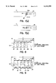
- FIGS. 5(a) through 5(f) show a process diagram which illustrates a third embodiment of the method of the present invention for setting lead frame conveying data, the process diagram being a continuation of the process diagram shown in FIGS. 1(a) through 1(f);
- FIGS. 6(a) through 6(e) show a process diagram which illustrates a fourth embodiment of the method of the present invention for setting lead frame conveying data, the process diagram being a continuation of the process diagram shown in FIGS. 1(a) through 1(f);
- FIGS. 7(a) and 7(b) shows a process diagram which is a continuation of the process diagram shown in FIGS. 6(a) through 6(e);
- FIG. 8 is a plan view of a lead frame which has islands arranged at a constant pitch
- FIG. 9 is a plan view of a lead frame which has islands with irregular pitch in between;
- FIG. 10 illustrates a lead frame conveying device, in which FIG. 10(a) is a schematic plan view, and FIG. 10(b) is a front view; and
- FIG. 11 is a block diagram of the control device used in the method of the present invention for setting lead frame conveying data.
- the frame feeder 3 includes feeding claws 4 consisting of an upper claw 4a and a lower claw 4b, and these feeding claws 4 are installed on a claw holder 5 (see FIG. 11) so that the claws 4 are opened and closed by a claw open/close motor 6.
- a claw holder 5 is caused to move along frame conveying path 3a of the frame feeder 3 by a claw feeding motor 7.
- the frame feeder 3 of this type is disclosed in, for example, Japanese Patent Application Publication (Kokoku) No. S63-56122 and Japanese Patent Application Laid-Open (Kokai) No. H4-346446, which are listed above in the Prior Art section of this specification.
- a bonding apparatus 10 such as a wire bonding apparatus, die bonding apparatus, etc. is installed on one side of the frame conveying path 3a so as to face the bonding position 3b.
- the bonding apparatus 10 includes an XY table 11, and this XY table 11 is driven in the X-Y (horizontal) directions by an XY table motor 12.
- a bonding head 13 is mounted on the XY table 11, and a camera holder 15 is fastened to this bonding head 13; in addition, a television camera 14 is mounted on the camera holder 15.
- a bonding arm 17 to which a bonding tool 16 is attached is installed on the bonding head 13 so that the bonding arm 17 can move up and down in FIG. 10(b).
- the television camera 14 is positioned above the bonding position 3b, and the bonding tool 16 is offset by a distance of Y1 with respect to the television camera 14 as best seen in FIG. 10(a).
- the bonding arm 17 is raised and lowered by a Z (raising-and-lowering) motor (not shown).
- a loader side magazine 20A and an unloader side magazine 20B are provided at the respective ends of the frame conveying path 3a of the frame feeder 3.
- the loader side magazine 20A and unloader side magazine 20B are positioned and carried on magazine holders 22 which are respectively driven upward and downward by a loader side elevator device 21A and an unloader side elevator device 21B.
- Lead frames 1 (1A shown in FIG. 8 or 1B shown in FIG. 9) inside the loader side magazine 20A are pushed out onto the frame conveying path 3a by a frame pusher 23.
- elevator devices 21A and 21B are disclosed in, for instance, Japanese Patent Application Publication (Kokoku) Nos. H1-32127 and H2-4486 and in Japanese Patent Application Laid-Open (Kokai) No. S63-56122.
- the reference numeral 24 is a photo sensor which detects lead frames 1 pushed out by the frame pusher 23.
- FIG. 11 shows the control device for the bonding apparatus of FIG. 10.
- the claw open/close motor 6 and the claw feeding motor 7 of the frame feeder 3, and the XY table motor 12 of the bonding apparatus 10 are respectively controlled by motor drivers 30, 31 and 32; and these motor drivers 30, 31 and 32 can be directly driven by a manual input means 33 through a main control section 34.
- motor drivers 30, 31 and 32 can be directly driven by a manual input means 33 through a main control section 34.
- various types of data are inputted into a data memory 36 via the main control section 34 using the manual input means 33.
- the data stored in the data memory 36 are processed by a calculation processing section 37 as respective data for controlling the motor drivers 30, 31 and 32; and such processed data are also stored in the data memory 36.
- the images picked up or imaged by the television camera 14 are subjected to image processing by an image processor 38, and the resulting processed images are displayed on a television monitor 39.
- image processing by an image processor 38
- Various types of data and setting modes stored in the data memory 36 are selected and displayed on the television monitor 39 by way of the manual input means 33.
- the lead frames used in this embodiment is the one shown in FIG. 8; and therefore, the lead frame 1A has islands 2A, 2B . . . 2F installed at a constant pitch distance d, and the first pitch c is approximately (1/2) ⁇ d.
- frame mode displayed on the television monitor 39 is selected using the manual input means 33 shown in FIG. 11.
- data input conditions stored in the control memory 35 are displayed on the television monitor 39 via the main control section 34.
- the number n representing the number of the islands 2A, 2B . . . 2F on the lead frame 1A is inputted using the manual input means 33.
- the lead frame shown in FIG. 8 has six islands; therefore, n is 6, and "6" is inputted via the manual input means 33.
- Data of this number n is stored in the data memory 36 through the main control section 34. In cases where the number of islands n does not change when the type of lead frame to be handled changes, there is of course no need to input the number n of the islands.
- this pre-programmed process is to chuck, by the feeding claws 4, a lead frame 1A which is pushed out of the loader side magazine 20A by the frame pusher 23 and then to bring, by the feeding claws 4, the leading end of the lead frame 1A to the vicinity of the bonding position 3b.
- the distance E from the photo sensor 24 shown in FIG. 1(a) to the frame holder 45 of the feeding claws 4 the distance F from the position of the lead frame 1A shown in FIG. 1(b) to an alignment position 46 (i. e., the leading end aligning position) shown in FIG. 1(d), and the distance G from the alignment position 46 to the bonding position 3b, are stored in the data memory 36 beforehand.
- the frame pusher 23 pushes out a lead frame 1A at a low speed from the state shown in FIG. 1(a) until this lead frame 1A is detected by the photo sensor 24.
- the feeding claws 4 are in an open state.
- the photo sensor 24 detects the lead frame 1A
- the low-speed pushing action of the frame pusher 23 is terminated; and the frame pusher 23 pushes out the lead frame 1A by the distance E as shown in FIG. 1(b).
- the feeding claws 4 are put in a state which allows the feeding claws 4 to chuck the lead frame 1A.
- the feeding claws 4 are closed and chuck the lead frame 1A; and as shown in FIG. 1(c), the feeding claws 4 are moved to a point which is slightly beyond the alignment position 46 stored in the data memory; in other words, the feeding claws 4 are moved a distance which is slightly greater than the distance F.
- the feeding claws 4 are opened so as to release the lead frame 1A, and the feeding claws 4 are moved slightly in the direction of arrow 47. Then, if the frame feeder described in the Japanese Patent Application Publication (Kokoku) No. S63-56122 is used, the feeding claws 4 are closed and moved in the direction of arrow 48, so that the leading end of the lead frame 1A is pushed back by the feeding claws 4, thus causing the leading end of the lead frame 1A to be positioned in the alignment position 46 as shown in FIG. 1(d). Then, after again being moved slightly in the direction of arrow 49, the feeding claws 4 are opened and then moved in the direction of arrow 50, so that the feeding claws 4 chuck the lead frame 1A as shown in FIG.
- the feeding claws 4 in an open state are moved in the direction of arrow 48 after a positioning pin (not shown) projects into the frame conveying path 3a, so that the leading end of the lead frame 1A is pushed back by the positioning pin, thus causing the leading end of the lead frame 1A to be positioned at the alignment position 46. Then, the feeding claws 4 are again moved slightly in the direction of arrow 49 and subsequently moved in the direction of arrow 50, so that the feeding claws 4 can chuck the lead frame 1A as shown in FIG. 1(e).
- the feeding claws 4 are closed so as to chuck the lead frame 1A and then moved the distance G stored in the data memory 36.
- the leading end of the lead frame 1A is automatically brought to the vicinity of the bonding position 3b.
- the feeding system of the feeding claws 4 of the frame feeder contains mechanical error; accordingly, in the state shown in FIG. 1(f), the leading end of the lead frame 1A does not coincide with the bonding position 3b.
- FIG. 2(a) shows the same state as FIG. 1(f).
- the feeding claws 4 are moved using the manual input means 33 so that the first island 2A of the lead frame is aligned with an island groove 61 formed in the bonding stage 60 (see FIG. 3) at the bonding position 3b.
- the reference numeral 62 is a heater.
- a universally known electrical chessman which moves cross-hairs 39a formed on the television monitor 39 is operated so that the cross-hairs 39a of the television monitor 39 are aligned with an arbitrary position (data point) on the first island 2A (for instance, one of the corners of the first island 2A) in the image of the first island 2A which is picked up or imaged by the television camera 14 and then displayed on the television monitor 39.
- a switch is pressed, so that data indicating the distance H by which the lead frame 1A has been moved or fed by the feeding claws 4 from the state shown in FIGS. 1(f) and 2(a) to the state shown in FIG. 2(b) is stored in the data memory 36.
- the position of the cross-hairs 39a acts as a mark for setting the next island.
- the feeding claws 4 are moved using the manual input means 33 so that the lead frame 1A is moved or fed until the last island 2F thereon reaches the position of the island groove 61 of the bonding stage 60 at the bonding position 3b.
- the feeding of the lead frame 1A in this case is either continuous feeding or intermittent feeding done by the reciprocating movement of the feeding claws 4.
- the feeding claws 4 are moved using the manual input means 33 so that an arbitrary position (data point) on the last island 2F (in this case, one of the corner portions of the last island 2F) is aligned with the cross-hairs 39a of the television monitor 39.
- the lead frame 1A is conveyed and accommodated in the unloader side magazine 20B by the unloader side feeding claws (not shown).
- the calculation processing section 37 uses the number of islands n and the distance B from the first island 2A to the last island 2F in the data, calculates the constant pitch distance D using Equation 2 below; and the calculation processing section 37 calculates the first pitch C and the frame length A using Equation 3 and Equation 4
- the data required for conveying the changed lead frame 1A can be set by performing:
- a lead frame 1A is fed so that the first island 2A is positioned at the bonding position 3b,
- the cross-hairs 39a of the television monitor 39 are aligned with an arbitrary position (data point) on the first island 2A, and
- the amount in which the lead frame 1A has been moved or fed in this case is stored in the data memory 36, and
- the lead frame 1A is fed so that an arbitrary position on the last island 2F of the lead frame that corresponds to the arbitrary position on the first island 2A is aligned with the cross-hairs 39a of the television monitor 39, and
- the amount in which the lead frame 1A has been moved or fed in this case is stored in the data memory 36.
- a data setting is accomplished by moving or feeding the lead frame 1A by the feeding claws 4 of the frame feeder, which actually involves a certain amount of error; accordingly, a data setting which involves this error can be accomplished during the setting operation, so that there is no need to check the conveyance or to perform fine adjustments after the completion of data setting.
- each lead frame 1A that is pushed out of the loader side magazine 20A by the frame pusher 23 is positioned by the process illustrated in FIGS. 1(a) through 1(d), thus performing the leading end alignment operation of the lead frame; the feeding claws 4 are moved by a distance that corresponds to the data (G+H) stored in the data memory 36, thus positioning the first island 2A at the bonding position 3b; a bonding pattern including a device bonded to the first island 2A is detected by the television camera 14; next, the control device corrects the coordinates stored in the bonding coordinate memory in accordance with the positional deviation that is detected; bonding is performed by the bonding apparatus 10; following the completion of bonding, the lead frame 1A is moved by the constant pitch distance D stored in the data memory so that the second island 2B is positioned at the bonding position; bonding is performed to the second island 2B by the same operation as that described above; the above operation is successively
- FIG. 4 illustrates a second embodiment of the present invention.
- a lead frame of the type 11B shown in FIG. 9 which has irregularly pitched islands are used, and this lead frame 1B has the first pitch c which is approximately equal to (1/2) ⁇ d.
- the number n of islands 2A, 2B . . . 2F on the lead frame 1B is inputted using the manual input means 33; and, by way of the manual input means 33, frame teaching is selected in the frame mode displayed on the television monitor 39.
- the leading end of the lead frame 1B is automatically conveyed to the vicinity of the bonding position 3b as shown in FIG. 1(f) because of the process taken as shown in FIGS. 1(a) through 1(f) as in the case of the first embodiment.
- the pitches D1 through D5 of the respective islands are going to be set as described below, the number of islands n can be automatically stored in the data memory 36.
- FIG. 4(a) is performed. This process is the same as the process shown in FIG. 2(b) of the first embodiment. More specifically, as shown in FIG. 4(a), the feeding claws 4 are moved using the manual input means 33 so that the first island 2A is aligned with an island groove 61 of the bonding stage 60 which is at the bonding position 3b. After it has been visually confirmed by means of a microscope that the first island 2A is aligned with the island groove 61, a universally known electrical chessman which moves the cross-hairs 39a of the television monitor 39 is operated so that the cross-hairs 39a of the television monitor 39 are aligned with an arbitrary position (data point) on the first island 2A, e.
- the feeding claws 4 are moved using the manual input means 33 so that a comer portion of the second island 2B is aligned with the cross-hairs 39a of the television monitor 39 as in the same manner as in the positioning of the first island 2A shown in FIG. 4(a).
- the set button is pressed.
- the distance D1 by which the lead frame 1B has been moved or fed from the position shown in FIG. 4(a) to the position shown in FIG. 4(b) is stored in the data memory 36.
- FIG. 4(c) shows the state that the positioning of the last island 2F has been completed.
- the pitch distances D2, D3, D4 and D5 are stored in the data memory 36.
- the lead frame 1B is accommodated inside the unloader side magazine 20B by the unloader side feeding claws (not shown).
- the number of times that the set button is pressed, when the respective islands are aligned with the cross-hairs 39a is stored in the data memory 36 as the number of islands n.
- the data required for the conveying of the changed lead frames 1B can be set by:
- a lead frame 1B is fed so that the first island 2A is positioned at the bonding position 3b,
- the cross-hairs 39a of the television monitor 39 are aligned with an arbitrary position (data point) on the first island 2A, and
- the amount in which the lead frame 1B has been moved or fed in this case is stored in the data memory 36, and a
- the lead frame 1B is fed so that arbitrary positions (data points) on the respective islands 2B, 2C . . . 2F following the first island 2A (each of the arbitrary positions corresponding to the arbitrary position on the first island 2A) are aligned with the cross-hairs 39a of the television monitor 39, and
- the respective amounts in which the lead frame 1B has been moved or fed in each of the cases are stored in the data memory 36.
- a data setting is accomplished by moving or feeding a lead frame 1B by the feeding claws 4 of the frame feeder, which actually involves a certain amount of error; accordingly, a data setting which involves this error can be accomplished during the setting operation, so that there is no need to check the conveyance or to perform fine adjustments after the completion of data setting.
- FIG. 5 illustrates the third embodiment of the present invention.
- lead frames of the type 1A shown in FIG. 8 are handled as in the first embodiment; however, unlike in the first embodiment, the first pitch c of the lead frame 1A is not roughly 1/2 of the constant pitch distance d. Accordingly, in this third embodiment, the leading end and trailing end of the lead frame 1A are checked in addition to the processes performed in the first embodiment.
- the leading end of the lead frame 1A is automatically brought to the vicinity of the bonding position 3b as shown in FIG. 1(f) by way of the process shown in FIGS. 1(a) through 1(f) as in the first embodiment.
- the cross-hairs 39a of the television monitor 39 are aligned with the leading end of the lead frame 1A, and the set button is pressed.
- the cross-hairs 39a are moved by operating an electrical chessman as described in the first embodiment.
- the feeding claws 4 are moved using the manual input means 33 so that the first island 2A of the lead frame 1A is aligned with the island groove 61 of the bonding stage 60 at the bonding position 3b.
- the cross-hairs 39a of the television monitor 39 are aligned with the position of the right end of the first island 2A, and the set button is pressed.
- the cross-hairs 39a of the television monitor 39 are aligned with the position of the left end of the first island 2A, and the set button is pressed.
- the distance I in which the lead frame 1A has been moved or fed and the distances J and K in which the cross-hairs 39a have been moved are stored in the data memory 36.
- the movement distances J and K of the cross-hairs 39a are amounts of movement on the screen of the television monitor 39 and thus have parameters that are different from those of the amount of feeding of the lead frame 1A (in other words, the amount of feeding of the feeding claws 4). Accordingly, these movement distances J and K are converted into the amounts of feeding of the lead frame 1A by the calculation processing section 37 and then stored in the data memory 36.
- the cross-hairs 39a are moved by an electrical chessman so as to obtain the data J and K; however, it is also possible to move the television camera 14 so that the left-end position and right-end position of the first island 2A are aligned with the cross-hairs 39a.
- the calculation processing section 37 calculates the first pitch C using Equation 5.
- the cross-hairs 39a of the television monitor 39 are moved and aligned with an arbitrary position (data point) on the first island 2A, e.g., with one of the comer portions of the first island 2A; and then, the switch is pressed. This position of the cross-hairs 39a acts as a mark for the setting of the next island.
- the process shown in FIG. 5(d) is the same as the process shown in FIG. 2(b).
- the feeding claws 4 are moved using the manual input means 33 so that the lead frame 1A is moved until the last island 2F is brought to the position of the island groove 61 of the bonding stage 60 at the bonding position 3b.
- the feeding claws 4 are moved using the manual input means 33 so that an arbitrary position (data point) on the last island 2F (in this case, one of the corner portions of the last island 2F) is aligned with the cross-hairs 39a of the television monitor 39.
- a feeding operation is performed by the feeding claws 4 until the trailing end of the lead frame 1A is aligned with the cross-hairs 39a of the television monitor 39; then, the set button is pressed so that the feeding distance L in this case is stored in the data memory 36.
- the calculation processing section 37 calculates the length A of the lead frame 1 using Equation 6 below.
- the lead frame 1A is conveyed into the unloader side magazine 20B by the unloader side feeding claws (not shown).
- the data required for conveying the changed lead frame 1A can be set by:
- a seventh process in which the lead frame 1A is then fed so that the trailing end of the lead frame 1A is aligned with the cross-hairs 39a of the television monitor 39, and the amount in which the lead frame 1A has been moved or fed in this case is stored in the data memory 36.
- a data setting is accomplished by moving or feeding a lead frame 1A by the feeding claws 4 of the frame feeder, which actually involves a certain amount of error; accordingly, a data setting which involves this error can be accomplished during the setting operation, so that there is no need to check the conveyance or to perform fine adjustments after the completion of data setting.
- FIGS. 6 and 7 illustrate a fourth embodiment of the present invention.
- the lead frame of the type 1B shown in FIG. 9 are to be handled, and the first pitch c is not equal to (1/2) ⁇ d.
- FIGS. 6(a) through 6(c) illustrate a process in which the first pitch c is set in the same manner as in FIGS. 5(a) through 5(c);
- FIGS. 6(d), 6(e) and 7(a) illustrate a process in which the pitch distances D1, D2, D3, D4 and D5 are set in the same manner as in FIGS. 4(a) through 4(d);
- FIG. 7(b) illustrates a process in which the trailing end of the lead frame 1B (i. e., the frame length A) is set in the same manner as in FIG. 5(f). Accordingly, a detailed description of the process from FIG. 6(a) through FIG. 7(b) is omitted, and it is obvious that the data setting is accomplished by the same way as described with reference to FIGS. 5(a) through 5(c), FIGS. 4(a) through 4(d) and FIG. 5(f).
- the alignment of the islands with the island groove 61 of the bonding stage 60 is confirmed by visual inspection using a microscope. However, this is done merely for confirmation and is not absolutely necessary. Furthermore, in the above embodiments, a description is made in regards to the bonding stage 60 that has an island groove 61; however, the present invention can be of course used for a bonding stage that has no island groove.
- the manual input means 33 is used for feeding the lead frame 1A as shown in FIGS. 2(b) and 2(c) in the first embodiment, for feeding the lead frame 1A as shown in FIGS. 4(a) through 4(c) in the second embodiment, for feeding the lead frame 1A as shown in FIGS. 5(a) through 5(f) in the third embodiment, and for feeding the lead frame 1B as shown in FIGS. 6(a) through 6(e) and FIGS. 7(a) and 7(b) in the fourth embodiment.
- the processes for four types of systems comprising respective combinations of lead frame types (either 1A or 1B as shown in FIG. 8 or FIG. 9) and first pitches c (lead frames 1A or 1B in which the first pitch c is either roughly equal to 1/2 of the constant pitch distance d or not equal to 1/2 of the constant pitch distance d), i. e., the process shown in FIGS. 2(a) and 2(b) in the case of the first type, the process shown in FIGS. 4(a) through 4(c) in the case of the second type, the process shown in FIGS. 5(a) through 5(f) in the case of the third type and the process shown in FIGS. 6(a) through 6(e) and FIGS.
- the lead frame 1A is automatically fed, and pattern recognition is performed so that the respective patterns of the islands 2A and 2F are recognized, after which the positions of the islands are automatically set.
- the lead frame 1B is automatically fed, and pattern recognition is performed so that the respective patterns of islands 2A through 2F are recognized, after which the positions of the islands are automatically set.
- the lead frame 1A is automatically fed, and pattern recognition is performed so that the respective patterns of the leading end of the lead frame 1A, one end (right end) position of the first island 2A, another end (left end) position of the first island 2A, an arbitrary position on the first island 2A and an arbitrary position on the last island 2F, are recognized; and then these positions are automatically set.
- the lead frame 1B is fed and pattern recognition is performed by means of a process combined by the processes shown in FIGS. 4 and 5, so that the positions in question are automatically set.
- the number of islands n is automatically stored in the data memory 36.
- the distance B from the first island 2A to the last island 2F is determined in order to calculate the pitch distance D in the case of lead frames 1A in which the islands have a constant pitch.
Landscapes
- Die Bonding (AREA)
- Wire Bonding (AREA)
Applications Claiming Priority (2)
| Application Number | Priority Date | Filing Date | Title |
|---|---|---|---|
| JP20529596A JP3298795B2 (ja) | 1996-07-16 | 1996-07-16 | リードフレームの搬送データ設定方法 |
| JP8-205295 | 1996-07-16 |
Publications (1)
| Publication Number | Publication Date |
|---|---|
| US6141599A true US6141599A (en) | 2000-10-31 |
Family
ID=16504610
Family Applications (1)
| Application Number | Title | Priority Date | Filing Date |
|---|---|---|---|
| US08/892,854 Expired - Fee Related US6141599A (en) | 1996-07-16 | 1997-07-15 | Method for setting conveying data for a lead frame |
Country Status (4)
| Country | Link |
|---|---|
| US (1) | US6141599A (ja) |
| JP (1) | JP3298795B2 (ja) |
| KR (1) | KR100274136B1 (ja) |
| TW (1) | TW410408B (ja) |
Cited By (3)
| Publication number | Priority date | Publication date | Assignee | Title |
|---|---|---|---|---|
| US20050097729A1 (en) * | 2003-11-11 | 2005-05-12 | Beat Bolli | Apparatus for mounting semiconductor chips |
| US20110055748A1 (en) * | 2009-09-03 | 2011-03-03 | Johnson Controls Technology Company | Systems and methods for mapping building management system inputs |
| US20110071685A1 (en) * | 2009-09-03 | 2011-03-24 | Johnson Controls Technology Company | Creation and use of software defined building objects in building management systems and applications |
Families Citing this family (1)
| Publication number | Priority date | Publication date | Assignee | Title |
|---|---|---|---|---|
| JP4839251B2 (ja) * | 2007-03-26 | 2011-12-21 | 株式会社新川 | ワイヤボンディング方法 |
Citations (15)
| Publication number | Priority date | Publication date | Assignee | Title |
|---|---|---|---|---|
| US4255851A (en) * | 1978-12-06 | 1981-03-17 | Western Electric Company, Inc. | Method and apparatus for indelibly marking articles during a manufacturing process |
| US4543659A (en) * | 1982-09-22 | 1985-09-24 | Tokyo Shibaura Denki Kabushiki Kaisha | Method for recognizing a pellet pattern |
| JPS6356122A (ja) * | 1986-08-25 | 1988-03-10 | 三菱電機株式会社 | 保護継電器の点検装置 |
| JPS6432127A (en) * | 1987-07-28 | 1989-02-02 | Nippon Ceramic Kk | Support for infrared detecting element |
| JPH024486A (ja) * | 1988-06-23 | 1990-01-09 | Fuji Valve Co Ltd | ワークの異材選別装置 |
| US4896418A (en) * | 1987-08-07 | 1990-01-30 | Texas Instrument Incorporated | Direct mounting method for semiconductors |
| US5003692A (en) * | 1989-05-17 | 1991-04-02 | Matsushita Electric Industrial Co., Ltd. | Electric component mounting method |
| US5125036A (en) * | 1985-05-20 | 1992-06-23 | Kulicke & Soffa Industries, Inc. | Video bond lead locator |
| US5163222A (en) * | 1988-02-26 | 1992-11-17 | Esec, Sa | Method and apparatus for loading metal leadframes with electronic components |
| JPH04346446A (ja) * | 1991-05-24 | 1992-12-02 | Shinkawa Ltd | リードフレームの搬送装置 |
| JPH05275502A (ja) * | 1992-03-26 | 1993-10-22 | Shinkawa Ltd | ワイヤボンデイング装置 |
| US5768759A (en) * | 1996-11-19 | 1998-06-23 | Zevatech, Inc. | Method and apparatus for reflective in-flight component registration |
| US5787577A (en) * | 1996-08-16 | 1998-08-04 | Motorola, Inc. | Method for adjusting an electronic part template |
| US5894659A (en) * | 1996-03-18 | 1999-04-20 | Motorola, Inc. | Method for inspecting lead frames in a tape lead bonding system |
| US5896652A (en) * | 1996-05-08 | 1999-04-27 | Tenryu Technics Co., Ltd. | Method of packaging electronic components |
Family Cites Families (1)
| Publication number | Priority date | Publication date | Assignee | Title |
|---|---|---|---|---|
| JPS55120144A (en) * | 1979-03-08 | 1980-09-16 | Sharp Corp | Automatic wire bonding system for semiconductor |
-
1996
- 1996-07-16 JP JP20529596A patent/JP3298795B2/ja not_active Expired - Fee Related
-
1997
- 1997-05-05 TW TW086106037A patent/TW410408B/zh not_active IP Right Cessation
- 1997-06-17 KR KR1019970025003A patent/KR100274136B1/ko not_active Expired - Fee Related
- 1997-07-15 US US08/892,854 patent/US6141599A/en not_active Expired - Fee Related
Patent Citations (15)
| Publication number | Priority date | Publication date | Assignee | Title |
|---|---|---|---|---|
| US4255851A (en) * | 1978-12-06 | 1981-03-17 | Western Electric Company, Inc. | Method and apparatus for indelibly marking articles during a manufacturing process |
| US4543659A (en) * | 1982-09-22 | 1985-09-24 | Tokyo Shibaura Denki Kabushiki Kaisha | Method for recognizing a pellet pattern |
| US5125036A (en) * | 1985-05-20 | 1992-06-23 | Kulicke & Soffa Industries, Inc. | Video bond lead locator |
| JPS6356122A (ja) * | 1986-08-25 | 1988-03-10 | 三菱電機株式会社 | 保護継電器の点検装置 |
| JPS6432127A (en) * | 1987-07-28 | 1989-02-02 | Nippon Ceramic Kk | Support for infrared detecting element |
| US4896418A (en) * | 1987-08-07 | 1990-01-30 | Texas Instrument Incorporated | Direct mounting method for semiconductors |
| US5163222A (en) * | 1988-02-26 | 1992-11-17 | Esec, Sa | Method and apparatus for loading metal leadframes with electronic components |
| JPH024486A (ja) * | 1988-06-23 | 1990-01-09 | Fuji Valve Co Ltd | ワークの異材選別装置 |
| US5003692A (en) * | 1989-05-17 | 1991-04-02 | Matsushita Electric Industrial Co., Ltd. | Electric component mounting method |
| JPH04346446A (ja) * | 1991-05-24 | 1992-12-02 | Shinkawa Ltd | リードフレームの搬送装置 |
| JPH05275502A (ja) * | 1992-03-26 | 1993-10-22 | Shinkawa Ltd | ワイヤボンデイング装置 |
| US5894659A (en) * | 1996-03-18 | 1999-04-20 | Motorola, Inc. | Method for inspecting lead frames in a tape lead bonding system |
| US5896652A (en) * | 1996-05-08 | 1999-04-27 | Tenryu Technics Co., Ltd. | Method of packaging electronic components |
| US5787577A (en) * | 1996-08-16 | 1998-08-04 | Motorola, Inc. | Method for adjusting an electronic part template |
| US5768759A (en) * | 1996-11-19 | 1998-06-23 | Zevatech, Inc. | Method and apparatus for reflective in-flight component registration |
Cited By (4)
| Publication number | Priority date | Publication date | Assignee | Title |
|---|---|---|---|---|
| US20050097729A1 (en) * | 2003-11-11 | 2005-05-12 | Beat Bolli | Apparatus for mounting semiconductor chips |
| US7287317B2 (en) * | 2003-11-11 | 2007-10-30 | Unaxis International Trading Ltd. | Apparatus for mounting semiconductor chips |
| US20110055748A1 (en) * | 2009-09-03 | 2011-03-03 | Johnson Controls Technology Company | Systems and methods for mapping building management system inputs |
| US20110071685A1 (en) * | 2009-09-03 | 2011-03-24 | Johnson Controls Technology Company | Creation and use of software defined building objects in building management systems and applications |
Also Published As
| Publication number | Publication date |
|---|---|
| JPH1032215A (ja) | 1998-02-03 |
| TW410408B (en) | 2000-11-01 |
| JP3298795B2 (ja) | 2002-07-08 |
| KR980012144A (ko) | 1998-04-30 |
| KR100274136B1 (ko) | 2001-01-15 |
Similar Documents
| Publication | Publication Date | Title |
|---|---|---|
| US7610785B2 (en) | Work positioning device | |
| US6449516B1 (en) | Bonding method and apparatus | |
| EP0660657A1 (en) | Method and mounting device for mounting a component at a specific position | |
| JP3384335B2 (ja) | 自動組立装置および自動組立方法 | |
| JPH0795639B2 (ja) | 生産ラインにおける位置ずれ自動補正方法 | |
| EP1603382A2 (en) | Electronic component mounting apparatus and electronic component mounting method | |
| US6141599A (en) | Method for setting conveying data for a lead frame | |
| US7087457B2 (en) | Die bonding method and apparatus | |
| US6250534B1 (en) | Wire bonding method | |
| JP3101853B2 (ja) | ボンデイング座標のティーチング方法 | |
| US5772040A (en) | Workpiece conveying apparatus used with workpiece inspection device | |
| JP4308736B2 (ja) | 電子部品供給方法、同装置および表面実装機 | |
| JP2005353750A (ja) | 電子部品搭載装置の保守管理装置 | |
| EP0634791B1 (en) | Wire bonder and wire bonding method | |
| US5583756A (en) | Teaching method and teaching system for a bonding coordinate | |
| JP3404755B2 (ja) | ワイヤボンディング装置 | |
| KR100243086B1 (ko) | 리드프레임 다이본딩장치 및 그 방법 | |
| JPS6227735B2 (ja) | ||
| JPH0513635A (ja) | タイバー切断方法 | |
| JP2538418B2 (ja) | ダイボンディング装置 | |
| JP2513151Y2 (ja) | ボンディング装置 | |
| JP2000138240A (ja) | 位置認識手段の移動装置 | |
| JP2000079518A (ja) | 自動組立装置における画像認識装置および画像認識方法 | |
| JP2000249662A (ja) | テープキャリア欠陥検査装置及びテープキャリア欠陥検査装置における撮像手段の位置合わせ方法 | |
| KR0176546B1 (ko) | 로보트 장치 및 그것의 작업 위치 자동 교시 방법 |
Legal Events
| Date | Code | Title | Description |
|---|---|---|---|
| AS | Assignment |
Owner name: KABUSHIKI KAISHA SHINKAWA, JAPAN Free format text: ASSIGNMENT OF ASSIGNORS INTEREST;ASSIGNORS:MOCHIDA, TORU;TERAKADO, YOSHIMITSU;SEGURO, MASAYUKI;REEL/FRAME:008938/0648 Effective date: 19971113 |
|
| FEPP | Fee payment procedure |
Free format text: PAYOR NUMBER ASSIGNED (ORIGINAL EVENT CODE: ASPN); ENTITY STATUS OF PATENT OWNER: SMALL ENTITY |
|
| FPAY | Fee payment |
Year of fee payment: 4 |
|
| FPAY | Fee payment |
Year of fee payment: 8 |
|
| FEPP | Fee payment procedure |
Free format text: PAYER NUMBER DE-ASSIGNED (ORIGINAL EVENT CODE: RMPN); ENTITY STATUS OF PATENT OWNER: SMALL ENTITY Free format text: PAYOR NUMBER ASSIGNED (ORIGINAL EVENT CODE: ASPN); ENTITY STATUS OF PATENT OWNER: SMALL ENTITY |
|
| REMI | Maintenance fee reminder mailed | ||
| LAPS | Lapse for failure to pay maintenance fees | ||
| STCH | Information on status: patent discontinuation |
Free format text: PATENT EXPIRED DUE TO NONPAYMENT OF MAINTENANCE FEES UNDER 37 CFR 1.362 |
|
| FP | Lapsed due to failure to pay maintenance fee |
Effective date: 20121031 |