US6147396A - Power semiconductor module - Google Patents
Power semiconductor module Download PDFInfo
- Publication number
- US6147396A US6147396A US09/250,363 US25036399A US6147396A US 6147396 A US6147396 A US 6147396A US 25036399 A US25036399 A US 25036399A US 6147396 A US6147396 A US 6147396A
- Authority
- US
- United States
- Prior art keywords
- power semiconductor
- output lines
- interrupter
- semiconductor module
- module according
- Prior art date
- Legal status (The legal status is an assumption and is not a legal conclusion. Google has not performed a legal analysis and makes no representation as to the accuracy of the status listed.)
- Expired - Fee Related
Links
Images
Classifications
-
- H—ELECTRICITY
- H10—SEMICONDUCTOR DEVICES; ELECTRIC SOLID-STATE DEVICES NOT OTHERWISE PROVIDED FOR
- H10W—GENERIC PACKAGES, INTERCONNECTIONS, CONNECTORS OR OTHER CONSTRUCTIONAL DETAILS OF DEVICES COVERED BY CLASS H10
- H10W42/00—Arrangements for protection of devices
- H10W42/80—Arrangements for protection of devices protecting against overcurrent or overload, e.g. fuses or shunts
-
- H—ELECTRICITY
- H01—ELECTRIC ELEMENTS
- H01H—ELECTRIC SWITCHES; RELAYS; SELECTORS; EMERGENCY PROTECTIVE DEVICES
- H01H37/00—Thermally-actuated switches
- H01H37/74—Switches in which only the opening movement or only the closing movement of a contact is effected by heating or cooling
-
- H—ELECTRICITY
- H10—SEMICONDUCTOR DEVICES; ELECTRIC SOLID-STATE DEVICES NOT OTHERWISE PROVIDED FOR
- H10W—GENERIC PACKAGES, INTERCONNECTIONS, CONNECTORS OR OTHER CONSTRUCTIONAL DETAILS OF DEVICES COVERED BY CLASS H10
- H10W70/00—Package substrates; Interposers; Redistribution layers [RDL]
- H10W70/40—Leadframes
- H10W70/481—Leadframes for devices being provided for in groups H10D8/00 - H10D48/00
-
- H—ELECTRICITY
- H10—SEMICONDUCTOR DEVICES; ELECTRIC SOLID-STATE DEVICES NOT OTHERWISE PROVIDED FOR
- H10W—GENERIC PACKAGES, INTERCONNECTIONS, CONNECTORS OR OTHER CONSTRUCTIONAL DETAILS OF DEVICES COVERED BY CLASS H10
- H10W72/00—Interconnections or connectors in packages
- H10W72/50—Bond wires
- H10W72/541—Dispositions of bond wires
- H10W72/5449—Dispositions of bond wires not being orthogonal to a side surface of the chip, e.g. fan-out arrangements
-
- H—ELECTRICITY
- H10—SEMICONDUCTOR DEVICES; ELECTRIC SOLID-STATE DEVICES NOT OTHERWISE PROVIDED FOR
- H10W—GENERIC PACKAGES, INTERCONNECTIONS, CONNECTORS OR OTHER CONSTRUCTIONAL DETAILS OF DEVICES COVERED BY CLASS H10
- H10W74/00—Encapsulations, e.g. protective coatings
-
- H—ELECTRICITY
- H10—SEMICONDUCTOR DEVICES; ELECTRIC SOLID-STATE DEVICES NOT OTHERWISE PROVIDED FOR
- H10W—GENERIC PACKAGES, INTERCONNECTIONS, CONNECTORS OR OTHER CONSTRUCTIONAL DETAILS OF DEVICES COVERED BY CLASS H10
- H10W90/00—Package configurations
- H10W90/701—Package configurations characterised by the relative positions of pads or connectors relative to package parts
- H10W90/751—Package configurations characterised by the relative positions of pads or connectors relative to package parts of bond wires
- H10W90/756—Package configurations characterised by the relative positions of pads or connectors relative to package parts of bond wires between a chip and a stacked lead frame, conducting package substrate or heat sink
Definitions
- the invention relates to a power semiconductor module, including at least one power semiconductor component fastened on a lead frame, at least partly encapsulated by a housing and electrically conductively connected to a plurality of output lines.
- the power semiconductor module has an interrupter irreversibly interrupting at least load current-carrying output lines and/or electrically conductive connections between the power semiconductor component and at least the load current-carrying output lines, in the event that the temperature of the power semiconductor component exceeds a predetermined temperature threshold.
- a fault or a failure can never be completely ruled out, which is the case, in principle, with all electrical devices.
- One possible fault situation is, for example, a so-called break-down or melt-through.
- a low-resistance connection is produced between the supply voltage source and the output terminal or, in the case of a low-side switch, a low-resistance connection of the output terminal to the device ground is produced.
- the electric current through the connected load circuit of the respective power switch can no longer be influenced by the driving logic configuration. Consequently, the load current is limited only by the resistance of the load in the load circuit.
- the load current is limited only by the performance of the voltage supply and, consequently, by the internal resistance thereof. Consequently, a load current corresponding to the maximum current of the voltage supply permanently flows at the output of the power switch. That maximum load current typically causes uncontrolled heating of the power switch, which can cause a fire in the worst-case scenario.
- a fuse for example a thin resistance wire, is typically used as a precaution against such an occurrence.
- the fuses are connected into the load circuit between the supply voltage source and the semiconductor switch.
- the fuse interrupts the load circuit in the event of an excessively large current.
- a temperature sensor will typically be used which switches off the power switch in the event of excessive heating of the power switch that is caused, for example, by an excessively large load current or short-circuit current.
- U.S. Pat. No. 5,068,706 describes a three-phase rectifier having a fuse which melts in a defined manner if the semiconductor components exceed a predetermined temperature. That prevents the component from being destroyed.
- a power semiconductor module comprising a lead frame; at least one power semiconductor component fastened on the lead frame; a housing at least partly encapsulating the at least one power semiconductor component; a plurality of output lines electrically conductively connected to the at least one power semiconductor component, the output lines including load current-carrying output lines; electrically conductive connections between the at least one power semiconductor component and at least the load current-carrying output lines; and at least one interrupter irreversibly interrupting at least the load current-carrying output lines and/or the electrically conductive connections and at least the load current-carrying output lines, if a temperature of the at least one power semiconductor component exceeds a predetermined temperature threshold, the at least one interrupter formed of a material having a volume-expanding and/or an oxidizing and/or an explosive characteristic with an increasing temperature.
- the load circuit is irreversibly interrupted in a defined manner.
- This irreversible interruption destroys the power semiconductor component, which is unusable in any case.
- a very much higher level of damage, caused by an equipment fire, for example, is avoided.
- materials are provided in the housing of the power semiconductor module or are fixedly encapsulated by the housing by molding. When a previously specified, critical temperature is exceeded, those materials interrupt the load circuit in the power semiconductor switch in such a manner that the housing and/or the load current-carrying bonding wires and/or output lines are irreversibly destroyed.
- the housing is formed of a molding composition, and the at least one interrupter is contained at least partly as a constituent of the molding composition.
- the at least one interrupter at least partly contains explosive, or magnesium carbonate (MgCO 3 ), or silver bromide.
- the housing is formed of plastic material having a foaming characteristic when the predetermined temperature threshold is reached, and the at least one interrupter is contained in the plastic material.
- the at least one interrupter at least partly contains polyamide 6.6.
- the at least one interrupter is enclosed by the housing and is at least partly composed of an approximately ideal gas.
- the output lines are terminal lines
- the electrically conductive connections are bonding wires connecting the terminal lines to the at least one power semiconductor component.
- the at least one interrupter is disposed in direct proximity to the at least one power semiconductor component.
- the at least one power semiconductor component and the output lines define an intermediate region therebetween, and the at least one interrupter is at least partly disposed in the intermediate region.
- the electrically conductive connections are bonding wires contacting at least the load current-carrying output lines at a given contact location, and the at least one interrupter is also disposed in direct proximity to the given contact location.
- the bonding wires are formed of a material
- the output lines are formed of a material
- the at least one interrupter is at least partly alloyed in the material of at least one of the bonding wires and the output lines.
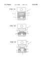
- FIGS. 1A to 1E are fragmentary, diagrammatic, plan views showing a structure of an inventive power semiconductor module for carrying out a method according to the invention, with interrupters disposed differently in a housing of the power semiconductor module;
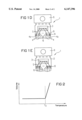
- FIG. 2 is a graph showing a temperature-volume characteristic curve of the interrupters which are used, that is striven for and is similar to a diode.
- FIGS. 1A to 1E there are seen various exemplary embodiments of a structure of an inventive power semiconductor module for carrying out a method according to the invention.
- identical or functionally identical parts are provided with the same reference symbols in the various exemplary embodiments.
- the power semiconductor module is designated by reference numeral 1.
- the power semiconductor module 1 includes a lead frame 2.
- An individual power semiconductor component 3 is mounted on the lead frame 2.
- the power semiconductor components 3 that are used are any type of power switches, such as, for example, high-side switches, low-side switches, bridge switches, etc.
- the inventive method and the inventive configuration can also be used with all other components in which uncontrolled levels of heating ought to be avoided as far as possible.
- the semiconductor component 3 is connected to the lead frame 2 through the use of a soft-soldering joint, for example.
- This soft-soldering joint typically has good electrical as well as good thermal conductivity.
- terminals 6, which are likewise electrically conductively connected to the lead frame 2 are terminal lines for a potential of a device ground.
- the power semiconductor module 1 additionally has a multiplicity of output lines 4, which are electrically conductively connected to corresponding contact points of the power semiconductor component 3 through connecting lines 5, in the present exemplary embodiment.
- Bonding wires are preferably used as the connecting lines 5.
- metal straps or the like are conceivable as the conductive connection.
- the terminal lines may include a further line system which is composed of sheet metal, for example.
- the load current-carrying output lines are designated by reference symbol 4a in FIG. 1D.
- the output lines 4 are spaced apart from the lead frame 2, and consequently from the power semiconductor component 3, by an interspace 9.
- the power semiconductor module is encapsulated in order to fix the output lines 4 in a defined manner relative to the lead frame 2 and also in order to protect the power semiconductor component 3 as well as its bonding wires 5 against external influences such as, for example, moisture, corrosion, mechanical stress, etc.
- the encapsulation which is illustrated by dashes in FIG. 1A, is provided by a housing 7 in such a way that only the output lines 4 and ground lines 6 project from the housing 7.
- the terminal lines 4, 6 are also the housing terminals in this case.
- the housing 7 is typically composed of plastic material but can also be composed of other materials. In this case, the plastic material is typically molded into the desired form during production.
- FIG. 1 a so-called TO housing structural part is shown in FIG. 1.
- the invention relates to all conceivable housing structural parts.
- Interrupters are designated by reference numeral 8.
- the interrupters 8 are fixedly encapsulated by molding or are part of the housing 7 itself. However, this is not absolutely necessary. It would also be conceivable for the interrupters to be disposed at least partly outside the housing 7, for example around the load current-carrying output lines 4a, outside the housing surface, etc.
- the material of the interrupters 8 which is also referred to as interruption material in the text below, is fixedly encapsulated by the housing 7 by molding or is part of the housing 7 itself.
- the housing 7 is typically destroyed by the interruption material in such a way that at least the load-carrying bonding wires 5 and/or at least the load-carrying output lines 4a and/or the power semiconductor component 3 itself are/is also destroyed or irreversibly interrupted.
- the load circuit of the power semiconductor component 3 is likewise interrupted.
- That temperature at which the semiconductor component is intended to be destroyed in a defined and reliable manner is referred to as a critical temperature Tz in the text below.
- the critical temperature is significantly above the temperature during normal operation of the semiconductor component, as well as above the temperatures arising in the production process of the housing structural part.
- interruption material 8 is part of the (current-carrying) output lines 4, 4a or the corresponding bonding wires 5 leading to the semiconductor component 3. In this case, these lines are destroyed directly by the interrupters 8.
- the interruption material changes the bonding wire 5 or the (load-carrying) output lines 4, 4a chemically, for example by oxidizing the interruption material.
- the bonding wires 5 or the output lines 4, 4a acquire a high resistance, as a result of which the load circuit is interrupted.
- the interruption material is alloyed into the material of the bonding wire 5 or of the output lines 4, 4a. It would also be conceivable for the interruption material to be contained on the surface of the output lines 4, 4a or the bonding wires 5 or in the line core thereof.
- the interruption material which, by way of example, but not necessarily, is a gas, changes its volume with increasing temperature in such a way that the interruption material expands to a very great extent as the temperature rises.
- the interruption material is fixedly enclosed by the housing 7 or is part of the housing 7, volume expansion of the interruption material with an increasing temperature is possible only to a limited extent.
- an increase in pressure is exerted on the housing 7. If the critical temperature is exceeded, the pressure has become too great for the housing 7, with the result that the housing 7 is abruptly destroyed.
- the bonding wires 5, which are constructed to be relatively thin in comparison with the output lines 4, are torn away or interrupted by the destruction of the housing 7 and the load current is reliably and irreversibly interrupted in a defined manner in this way.
- the additional material ignites or explodes starting from the critical temperature and, consequently, blows up the housing 7 and therefore the bonding wires 5 in an equivalent manner to that described under mechanism 2.
- a further possibility is the use of an interruption material which, starting from the critical temperature, begins to liberate a great deal of gas and in this way destroys the housing 7 and, consequently, also the bonding wires 5 in accordance with the 2 nd mechanism.
- a thoroughly effective measure would be the use of an explosive having an ignition temperature that lies in the region of the critical temperature.
- the ignition temperature of customary explosives usually lies in the range between 350° C. and 700° C.
- a firing pellet would be conceivable in this case as the interruption material, similarly to the case of an airbag.
- Silver bromide which ignites at a temperature of about 170° C., would also be conceivable.
- plastics as the housing material which, starting from the critical temperature, begin to expand to a great extent, for example by foaming (2 nd mechanism 2).
- foaming (2 nd mechanism 2).
- plastics polyamide or nylon 6.6. It would also be conceivable for this plastic material to be enclosed by the housing material.
- interruption materials which, starting from the critical temperature, oxidize to a great extent (1 st mechanism), such as, for example, magnesium carbonate (MgCO 3 ), would also be conceivable.
- MgCO 3 oxidizes to form CO 2 +MgO.
- FIGS. 1A to 1E a number of examples of a possible site for incorporation of the above-mentioned interruption materials are illustrated in FIGS. 1A to 1E.
- the interruption material is applied on a large area of the lead frame 2.
- the interruption material is disposed around the entire semiconductor component 3.
- the housing 7 is blown up, and consequently the bonding wires 5 are interrupted.
- the interruption material is disposed only on the edge of the lead frame 2 on the side toward the output lines 4.
- the bonding wires 5 are either immediately interrupted or are torn away from the semiconductor component 3 and/or its output lines 4 by virtue of the housing 7 blowing up at this location.
- the interrupters 8 are disposed only in the vicinity of those bonding wires 5 which connect the semiconductor component to the load current-carrying output lines 4a.
- the interrupters 8 are disposed exclusively at the contact point between the load current-carrying bonding wires and the corresponding output lines 4a.
- the interrupters 8 are disposed in the interspace 9 which separates the lead frame 2 and the output lines 4 from one another.
- interrupters prefferably be alloyed into the material of the bonding wires 5 and/or of the output lines 4.
- the alloying of the interrupters is preferred particularly when the corresponding lines are intended to be interrupted by oxidation when the critical temperature is reached in accordance with the 1 st mechanism.
- interrupters 8 are introduced directly into the plastic molding composition of the housing 7, which is likewise not illustrated in FIG. 1.
- the interruption is facilitated.
- the quantity of interruption material being used can thus be reduced.
- the direction in which the housing corner to be blown up is possibly hurled away can be defined. Consequently, the interruption is reproducible to the greatest possible extent and a possible hazard to sensitive parts in the vicinity can be avoided.
- FIGS. 1A to 1E are in no way exhaustive.
- the invention can be applied to all conceivable semiconductor components in which the current in the current-carrying line is intended to be interrupted when a critical temperature is reached.
- the critical temperature at which the semiconductor component is intended to be destroyed can equally be established by the targeted choice of the interruption materials being used and/or the proportioning thereof.
Landscapes
- Fuses (AREA)
Applications Claiming Priority (2)
| Application Number | Priority Date | Filing Date | Title |
|---|---|---|---|
| DE19805785A DE19805785C1 (de) | 1998-02-12 | 1998-02-12 | Leistungshalbleiter-Modul mit thermischer Laststromsicherung |
| DE19805785 | 1998-02-12 |
Publications (1)
| Publication Number | Publication Date |
|---|---|
| US6147396A true US6147396A (en) | 2000-11-14 |
Family
ID=7857534
Family Applications (1)
| Application Number | Title | Priority Date | Filing Date |
|---|---|---|---|
| US09/250,363 Expired - Fee Related US6147396A (en) | 1998-02-12 | 1999-02-12 | Power semiconductor module |
Country Status (3)
| Country | Link |
|---|---|
| US (1) | US6147396A (de) |
| EP (1) | EP0936670A2 (de) |
| DE (1) | DE19805785C1 (de) |
Cited By (6)
| Publication number | Priority date | Publication date | Assignee | Title |
|---|---|---|---|---|
| EP1282170A1 (de) * | 2001-07-30 | 2003-02-05 | Abb Research Ltd. | Kurzschlussfestes Leistungshalbleiterbauelement |
| US20040183168A1 (en) * | 2003-03-18 | 2004-09-23 | Himeji Toshiba E.P. Corporation | Lead frame and electronic component using same |
| US20050133855A1 (en) * | 2003-11-21 | 2005-06-23 | Infineon Technologies Ag | Semiconductor component arrangement with a defect identification circuit |
| WO2006018393A1 (de) * | 2004-08-18 | 2006-02-23 | Siemens Aktiengesellschaft | Blockierschutz für einen permanenterregten elektromotor-antrieb |
| US20070159745A1 (en) * | 2004-05-24 | 2007-07-12 | Sven Berberich | Circuit Element and Method for Protecting a Load Circuit |
| US20070200194A1 (en) * | 2006-02-28 | 2007-08-30 | Alfons Graf | Apparatus And Method For Temperature-Interrupting Protection Of An Electric Device |
Families Citing this family (12)
| Publication number | Priority date | Publication date | Assignee | Title |
|---|---|---|---|---|
| DE19902073A1 (de) * | 1999-01-20 | 2000-08-10 | Bosch Gmbh Robert | Elektrischer Leiter mit Zündeinrichtung |
| DE19936112A1 (de) * | 1999-07-31 | 2001-02-01 | Mannesmann Vdo Ag | Halbleiterschalter |
| DE10122363B4 (de) | 2001-05-09 | 2007-11-29 | Infineon Technologies Ag | Halbleitermodul |
| DE10137666A1 (de) | 2001-08-01 | 2003-02-27 | Infineon Technologies Ag | Schutzvorrichtung für Baugruppen und Verfahren zu ihrer Herstellung |
| DE10323492A1 (de) * | 2002-05-24 | 2003-12-04 | Bosch Gmbh Robert | Elektrisches Bauelement |
| DE10334433B4 (de) * | 2003-07-28 | 2009-10-22 | Infineon Technologies Ag | Vorrichtung zur Unterbrechung des Stromflusses zu einem oder von einem Halbleiterkörper eines Halbleiterbauelements |
| DE102005019875B8 (de) * | 2005-04-28 | 2008-08-07 | Airbus Deutschland Gmbh | Bohrlehre sowie Bohrvorrichtung |
| EP1906448A1 (de) * | 2006-09-29 | 2008-04-02 | Delphi Technologies, Inc. | Abgesichertes Feldeffekttransistorbauelement |
| DE102008056145A1 (de) * | 2008-11-06 | 2009-06-10 | Daimler Ag | Vorrichtung zum Schutz eines Halbleiterelements |
| DE102009047439B4 (de) | 2009-12-03 | 2020-01-02 | Robert Bosch Gmbh | Bauelement für eine Batterieanordnung mit elektrisch trennbarer Leiterbahn, Batterieanordnung und Betriebsverfahren dafür |
| EP3939063B1 (de) * | 2019-03-12 | 2022-10-26 | Signify Holding B.V. | Halter zum einrasten einer thermischen sicherung bei einer elektronischen komponente |
| DE102020213747A1 (de) | 2020-11-02 | 2022-05-05 | Robert Bosch Gesellschaft mit beschränkter Haftung | Verfahren zur Ansteuerung von mindestens zwei Halbleiterbauelementen in Parallelschaltung zur Trennung eines über einem vordefinierten Schwellenwert liegenden elektrischen Stroms |
Citations (5)
| Publication number | Priority date | Publication date | Assignee | Title |
|---|---|---|---|---|
| US5068706A (en) * | 1987-03-11 | 1991-11-26 | Kabushiki Kaisha Toshiba | Semiconductor device with fuse function |
| US5543632A (en) * | 1991-10-24 | 1996-08-06 | International Business Machines Corporation | Temperature monitoring pilot transistor |
| US5945728A (en) * | 1992-12-03 | 1999-08-31 | Linear Technology Corporation | Lead frame capacitor and capacitively coupled isolator circuit |
| US5998856A (en) * | 1996-11-28 | 1999-12-07 | Mitsubishi Denki Kabushiki Kaisha | Semiconductor device |
| US6002166A (en) * | 1996-11-28 | 1999-12-14 | Mitsubishi Denki Kabushiki Kaisha | Semiconductor device |
-
1998
- 1998-02-12 DE DE19805785A patent/DE19805785C1/de not_active Expired - Fee Related
- 1998-12-14 EP EP98123760A patent/EP0936670A2/de not_active Withdrawn
-
1999
- 1999-02-12 US US09/250,363 patent/US6147396A/en not_active Expired - Fee Related
Patent Citations (5)
| Publication number | Priority date | Publication date | Assignee | Title |
|---|---|---|---|---|
| US5068706A (en) * | 1987-03-11 | 1991-11-26 | Kabushiki Kaisha Toshiba | Semiconductor device with fuse function |
| US5543632A (en) * | 1991-10-24 | 1996-08-06 | International Business Machines Corporation | Temperature monitoring pilot transistor |
| US5945728A (en) * | 1992-12-03 | 1999-08-31 | Linear Technology Corporation | Lead frame capacitor and capacitively coupled isolator circuit |
| US5998856A (en) * | 1996-11-28 | 1999-12-07 | Mitsubishi Denki Kabushiki Kaisha | Semiconductor device |
| US6002166A (en) * | 1996-11-28 | 1999-12-14 | Mitsubishi Denki Kabushiki Kaisha | Semiconductor device |
Cited By (10)
| Publication number | Priority date | Publication date | Assignee | Title |
|---|---|---|---|---|
| EP1282170A1 (de) * | 2001-07-30 | 2003-02-05 | Abb Research Ltd. | Kurzschlussfestes Leistungshalbleiterbauelement |
| US20040183168A1 (en) * | 2003-03-18 | 2004-09-23 | Himeji Toshiba E.P. Corporation | Lead frame and electronic component using same |
| US20050133855A1 (en) * | 2003-11-21 | 2005-06-23 | Infineon Technologies Ag | Semiconductor component arrangement with a defect identification circuit |
| US7265566B2 (en) | 2003-11-21 | 2007-09-04 | Infineon Technologies Ag | Semiconductor component arrangement having a temperature-based defect identification |
| US20070159745A1 (en) * | 2004-05-24 | 2007-07-12 | Sven Berberich | Circuit Element and Method for Protecting a Load Circuit |
| US7684165B2 (en) | 2004-05-24 | 2010-03-23 | Fraunhofer-Gesellschaft Zur Foerderung Der Angewandten Forschung E.V. | Circuit element and method for protecting a load circuit |
| WO2006018393A1 (de) * | 2004-08-18 | 2006-02-23 | Siemens Aktiengesellschaft | Blockierschutz für einen permanenterregten elektromotor-antrieb |
| US20070262740A1 (en) * | 2004-08-18 | 2007-11-15 | Marcus Podack | Antilock System For A Permanently Excited Electric Motor Drive |
| US7508637B2 (en) | 2004-08-18 | 2009-03-24 | Brose Fahrzeugteile Gmbh & Co. Kommanditgesellschaft, Wuerzburg | Antilock system for a permanently excited electric motor drive |
| US20070200194A1 (en) * | 2006-02-28 | 2007-08-30 | Alfons Graf | Apparatus And Method For Temperature-Interrupting Protection Of An Electric Device |
Also Published As
| Publication number | Publication date |
|---|---|
| EP0936670A2 (de) | 1999-08-18 |
| DE19805785C1 (de) | 1999-06-17 |
Similar Documents
| Publication | Publication Date | Title |
|---|---|---|
| US6147396A (en) | Power semiconductor module | |
| US6735065B2 (en) | Semiconductor module | |
| US7875997B2 (en) | Circuit interruption device | |
| CN101983411B (zh) | 外部操作型热保护器 | |
| US4547830A (en) | Device for protection of a semiconductor device | |
| US20070159745A1 (en) | Circuit Element and Method for Protecting a Load Circuit | |
| US20210183607A1 (en) | Active/passive fuse module | |
| WO1998040942A1 (en) | Surge suppression device | |
| JP2002015648A (ja) | 回路遮断装置 | |
| GB2344476A (en) | Thermal fuse | |
| US6504467B1 (en) | Switch integral in a semiconductor element | |
| JP2001068000A (ja) | 回路遮断装置 | |
| JPH1055742A (ja) | 回路遮断器 | |
| US11594391B2 (en) | Active/passive fuse module | |
| JP2000324674A (ja) | ワイヤーハーネス装置 | |
| US20060043610A1 (en) | Power controller with bond wire fuse | |
| CN109564917B (zh) | 具有热熔断体的瞬变电压抑制装置 | |
| JPH11329189A (ja) | 電流遮断装置 | |
| JPH04237139A (ja) | 集積回路パッケージ | |
| US6667532B2 (en) | Semiconductor power component comprising a safety fuse | |
| US20070200194A1 (en) | Apparatus And Method For Temperature-Interrupting Protection Of An Electric Device | |
| JP2004095992A (ja) | 半導体装置 | |
| JP2000149747A (ja) | 回路遮断器 | |
| JP2621075B2 (ja) | 保護回路 | |
| KR101043517B1 (ko) | 압력 완화를 위한 전류 제한 장치 |
Legal Events
| Date | Code | Title | Description |
|---|---|---|---|
| AS | Assignment |
Owner name: SIEMENS AKTIENGESELLSCHAFT, GERMANY Free format text: ASSIGNMENT OF ASSIGNORS INTEREST;ASSIGNORS:TROGER, WOLFGANG;GRAF, ALFONS;REEL/FRAME:011043/0190 Effective date: 19990316 |
|
| FPAY | Fee payment |
Year of fee payment: 4 |
|
| REMI | Maintenance fee reminder mailed | ||
| FPAY | Fee payment |
Year of fee payment: 8 |
|
| SULP | Surcharge for late payment |
Year of fee payment: 7 |
|
| AS | Assignment |
Owner name: INFINEON TECHNOLOGIES AG, GERMANY Free format text: ASSIGNMENT OF ASSIGNORS INTEREST;ASSIGNOR:SIEMENS AKTIENGESELLSCHAFT;REEL/FRAME:023778/0173 Effective date: 20100112 |
|
| REMI | Maintenance fee reminder mailed | ||
| LAPS | Lapse for failure to pay maintenance fees | ||
| STCH | Information on status: patent discontinuation |
Free format text: PATENT EXPIRED DUE TO NONPAYMENT OF MAINTENANCE FEES UNDER 37 CFR 1.362 |
|
| FP | Lapsed due to failure to pay maintenance fee |
Effective date: 20121114 |