US6148599A - Process and apparatus for gasifying solid carbonaceous material having a high moisture content - Google Patents
Process and apparatus for gasifying solid carbonaceous material having a high moisture content Download PDFInfo
- Publication number
- US6148599A US6148599A US09/114,432 US11443298A US6148599A US 6148599 A US6148599 A US 6148599A US 11443298 A US11443298 A US 11443298A US 6148599 A US6148599 A US 6148599A
- Authority
- US
- United States
- Prior art keywords
- pressurised
- flue gas
- vessel
- carbonaceous
- fuel gas
- Prior art date
- Legal status (The legal status is an assumption and is not a legal conclusion. Google has not performed a legal analysis and makes no representation as to the accuracy of the status listed.)
- Expired - Fee Related
Links
- 239000007787 solid Substances 0.000 title claims abstract description 57
- 238000000034 method Methods 0.000 title claims abstract description 56
- 239000003575 carbonaceous material Substances 0.000 title claims abstract description 55
- UGFAIRIUMAVXCW-UHFFFAOYSA-N Carbon monoxide Chemical compound [O+]#[C-] UGFAIRIUMAVXCW-UHFFFAOYSA-N 0.000 claims abstract description 82
- 239000003546 flue gas Substances 0.000 claims abstract description 82
- 239000007789 gas Substances 0.000 claims abstract description 71
- 239000002737 fuel gas Substances 0.000 claims abstract description 60
- 239000000463 material Substances 0.000 claims abstract description 55
- 238000002485 combustion reaction Methods 0.000 claims abstract description 35
- QVGXLLKOCUKJST-UHFFFAOYSA-N atomic oxygen Chemical compound [O] QVGXLLKOCUKJST-UHFFFAOYSA-N 0.000 claims abstract description 19
- 239000001301 oxygen Substances 0.000 claims abstract description 19
- 229910052760 oxygen Inorganic materials 0.000 claims abstract description 19
- 230000005611 electricity Effects 0.000 claims abstract description 8
- 238000001035 drying Methods 0.000 claims description 30
- 238000002309 gasification Methods 0.000 claims description 15
- XLYOFNOQVPJJNP-UHFFFAOYSA-N water Substances O XLYOFNOQVPJJNP-UHFFFAOYSA-N 0.000 abstract description 15
- 239000000446 fuel Substances 0.000 abstract description 13
- 239000002002 slurry Substances 0.000 abstract description 4
- 239000003245 coal Substances 0.000 description 52
- 239000012530 fluid Substances 0.000 description 10
- 238000001816 cooling Methods 0.000 description 8
- 239000003513 alkali Substances 0.000 description 6
- 238000005516 engineering process Methods 0.000 description 6
- 229910052783 alkali metal Inorganic materials 0.000 description 5
- 150000001340 alkali metals Chemical class 0.000 description 5
- 238000010248 power generation Methods 0.000 description 5
- 239000011343 solid material Substances 0.000 description 5
- 238000010438 heat treatment Methods 0.000 description 4
- 239000003077 lignite Substances 0.000 description 4
- OKTJSMMVPCPJKN-UHFFFAOYSA-N Carbon Chemical compound [C] OKTJSMMVPCPJKN-UHFFFAOYSA-N 0.000 description 3
- 229910052799 carbon Inorganic materials 0.000 description 3
- 238000006243 chemical reaction Methods 0.000 description 3
- 238000007791 dehumidification Methods 0.000 description 3
- 230000001419 dependent effect Effects 0.000 description 3
- 238000012546 transfer Methods 0.000 description 3
- DGAQECJNVWCQMB-PUAWFVPOSA-M Ilexoside XXIX Chemical compound C[C@@H]1CC[C@@]2(CC[C@@]3(C(=CC[C@H]4[C@]3(CC[C@@H]5[C@@]4(CC[C@@H](C5(C)C)OS(=O)(=O)[O-])C)C)[C@@H]2[C@]1(C)O)C)C(=O)O[C@H]6[C@@H]([C@H]([C@@H]([C@H](O6)CO)O)O)O.[Na+] DGAQECJNVWCQMB-PUAWFVPOSA-M 0.000 description 2
- 238000011161 development Methods 0.000 description 2
- 230000000694 effects Effects 0.000 description 2
- 238000004519 manufacturing process Methods 0.000 description 2
- 238000002156 mixing Methods 0.000 description 2
- 239000000203 mixture Substances 0.000 description 2
- 238000011084 recovery Methods 0.000 description 2
- 238000003303 reheating Methods 0.000 description 2
- 229910052708 sodium Inorganic materials 0.000 description 2
- 239000011734 sodium Substances 0.000 description 2
- 238000012360 testing method Methods 0.000 description 2
- 238000011144 upstream manufacturing Methods 0.000 description 2
- 239000002028 Biomass Substances 0.000 description 1
- VEXZGXHMUGYJMC-UHFFFAOYSA-M Chloride anion Chemical compound [Cl-] VEXZGXHMUGYJMC-UHFFFAOYSA-M 0.000 description 1
- ZAMOUSCENKQFHK-UHFFFAOYSA-N Chlorine atom Chemical compound [Cl] ZAMOUSCENKQFHK-UHFFFAOYSA-N 0.000 description 1
- VEXZGXHMUGYJMC-UHFFFAOYSA-N Hydrochloric acid Chemical compound Cl VEXZGXHMUGYJMC-UHFFFAOYSA-N 0.000 description 1
- 230000009286 beneficial effect Effects 0.000 description 1
- 239000002802 bituminous coal Substances 0.000 description 1
- 238000003763 carbonization Methods 0.000 description 1
- 230000003197 catalytic effect Effects 0.000 description 1
- 239000000919 ceramic Substances 0.000 description 1
- 239000003795 chemical substances by application Substances 0.000 description 1
- 239000000460 chlorine Substances 0.000 description 1
- 229910052801 chlorine Inorganic materials 0.000 description 1
- 239000003034 coal gas Substances 0.000 description 1
- 230000007797 corrosion Effects 0.000 description 1
- 238000005260 corrosion Methods 0.000 description 1
- 238000013461 design Methods 0.000 description 1
- 238000007865 diluting Methods 0.000 description 1
- 238000004880 explosion Methods 0.000 description 1
- 229910000041 hydrogen chloride Inorganic materials 0.000 description 1
- IXCSERBJSXMMFS-UHFFFAOYSA-N hydrogen chloride Substances Cl.Cl IXCSERBJSXMMFS-UHFFFAOYSA-N 0.000 description 1
- 239000002245 particle Substances 0.000 description 1
- 239000011236 particulate material Substances 0.000 description 1
- 239000003415 peat Substances 0.000 description 1
- 230000009257 reactivity Effects 0.000 description 1
- 230000003134 recirculating effect Effects 0.000 description 1
- 230000000717 retained effect Effects 0.000 description 1
- 238000007789 sealing Methods 0.000 description 1
- 150000004760 silicates Chemical class 0.000 description 1
- 150000003467 sulfuric acid derivatives Chemical class 0.000 description 1
- 239000011269 tar Substances 0.000 description 1
- 230000008646 thermal stress Effects 0.000 description 1
- 239000002918 waste heat Substances 0.000 description 1
Images
Classifications
-
- C—CHEMISTRY; METALLURGY
- C10—PETROLEUM, GAS OR COKE INDUSTRIES; TECHNICAL GASES CONTAINING CARBON MONOXIDE; FUELS; LUBRICANTS; PEAT
- C10J—PRODUCTION OF PRODUCER GAS, WATER-GAS, SYNTHESIS GAS FROM SOLID CARBONACEOUS MATERIAL, OR MIXTURES CONTAINING THESE GASES; CARBURETTING AIR OR OTHER GASES
- C10J3/00—Production of combustible gases containing carbon monoxide from solid carbonaceous fuels
- C10J3/46—Gasification of granular or pulverulent flues in suspension
- C10J3/54—Gasification of granular or pulverulent fuels by the Winkler technique, i.e. by fluidisation
-
- C—CHEMISTRY; METALLURGY
- C10—PETROLEUM, GAS OR COKE INDUSTRIES; TECHNICAL GASES CONTAINING CARBON MONOXIDE; FUELS; LUBRICANTS; PEAT
- C10J—PRODUCTION OF PRODUCER GAS, WATER-GAS, SYNTHESIS GAS FROM SOLID CARBONACEOUS MATERIAL, OR MIXTURES CONTAINING THESE GASES; CARBURETTING AIR OR OTHER GASES
- C10J3/00—Production of combustible gases containing carbon monoxide from solid carbonaceous fuels
- C10J3/46—Gasification of granular or pulverulent flues in suspension
- C10J3/463—Gasification of granular or pulverulent flues in suspension in stationary fluidised beds
-
- C—CHEMISTRY; METALLURGY
- C10—PETROLEUM, GAS OR COKE INDUSTRIES; TECHNICAL GASES CONTAINING CARBON MONOXIDE; FUELS; LUBRICANTS; PEAT
- C10J—PRODUCTION OF PRODUCER GAS, WATER-GAS, SYNTHESIS GAS FROM SOLID CARBONACEOUS MATERIAL, OR MIXTURES CONTAINING THESE GASES; CARBURETTING AIR OR OTHER GASES
- C10J3/00—Production of combustible gases containing carbon monoxide from solid carbonaceous fuels
- C10J3/46—Gasification of granular or pulverulent flues in suspension
- C10J3/48—Apparatus; Plants
- C10J3/52—Ash-removing devices
- C10J3/523—Ash-removing devices for gasifiers with stationary fluidised bed
-
- C—CHEMISTRY; METALLURGY
- C10—PETROLEUM, GAS OR COKE INDUSTRIES; TECHNICAL GASES CONTAINING CARBON MONOXIDE; FUELS; LUBRICANTS; PEAT
- C10J—PRODUCTION OF PRODUCER GAS, WATER-GAS, SYNTHESIS GAS FROM SOLID CARBONACEOUS MATERIAL, OR MIXTURES CONTAINING THESE GASES; CARBURETTING AIR OR OTHER GASES
- C10J3/00—Production of combustible gases containing carbon monoxide from solid carbonaceous fuels
- C10J3/72—Other features
- C10J3/721—Multistage gasification, e.g. plural parallel or serial gasification stages
-
- C—CHEMISTRY; METALLURGY
- C10—PETROLEUM, GAS OR COKE INDUSTRIES; TECHNICAL GASES CONTAINING CARBON MONOXIDE; FUELS; LUBRICANTS; PEAT
- C10K—PURIFYING OR MODIFYING THE CHEMICAL COMPOSITION OF COMBUSTIBLE GASES CONTAINING CARBON MONOXIDE
- C10K1/00—Purifying combustible gases containing carbon monoxide
- C10K1/002—Removal of contaminants
- C10K1/007—Removal of contaminants of metal compounds
- C10K1/008—Alkali metal compounds
-
- C—CHEMISTRY; METALLURGY
- C10—PETROLEUM, GAS OR COKE INDUSTRIES; TECHNICAL GASES CONTAINING CARBON MONOXIDE; FUELS; LUBRICANTS; PEAT
- C10K—PURIFYING OR MODIFYING THE CHEMICAL COMPOSITION OF COMBUSTIBLE GASES CONTAINING CARBON MONOXIDE
- C10K1/00—Purifying combustible gases containing carbon monoxide
- C10K1/02—Dust removal
-
- C—CHEMISTRY; METALLURGY
- C10—PETROLEUM, GAS OR COKE INDUSTRIES; TECHNICAL GASES CONTAINING CARBON MONOXIDE; FUELS; LUBRICANTS; PEAT
- C10K—PURIFYING OR MODIFYING THE CHEMICAL COMPOSITION OF COMBUSTIBLE GASES CONTAINING CARBON MONOXIDE
- C10K1/00—Purifying combustible gases containing carbon monoxide
- C10K1/02—Dust removal
- C10K1/024—Dust removal by filtration
-
- C—CHEMISTRY; METALLURGY
- C10—PETROLEUM, GAS OR COKE INDUSTRIES; TECHNICAL GASES CONTAINING CARBON MONOXIDE; FUELS; LUBRICANTS; PEAT
- C10J—PRODUCTION OF PRODUCER GAS, WATER-GAS, SYNTHESIS GAS FROM SOLID CARBONACEOUS MATERIAL, OR MIXTURES CONTAINING THESE GASES; CARBURETTING AIR OR OTHER GASES
- C10J2200/00—Details of gasification apparatus
- C10J2200/15—Details of feeding means
- C10J2200/158—Screws
-
- C—CHEMISTRY; METALLURGY
- C10—PETROLEUM, GAS OR COKE INDUSTRIES; TECHNICAL GASES CONTAINING CARBON MONOXIDE; FUELS; LUBRICANTS; PEAT
- C10J—PRODUCTION OF PRODUCER GAS, WATER-GAS, SYNTHESIS GAS FROM SOLID CARBONACEOUS MATERIAL, OR MIXTURES CONTAINING THESE GASES; CARBURETTING AIR OR OTHER GASES
- C10J2300/00—Details of gasification processes
- C10J2300/09—Details of the feed, e.g. feeding of spent catalyst, inert gas or halogens
- C10J2300/0903—Feed preparation
- C10J2300/0909—Drying
-
- C—CHEMISTRY; METALLURGY
- C10—PETROLEUM, GAS OR COKE INDUSTRIES; TECHNICAL GASES CONTAINING CARBON MONOXIDE; FUELS; LUBRICANTS; PEAT
- C10J—PRODUCTION OF PRODUCER GAS, WATER-GAS, SYNTHESIS GAS FROM SOLID CARBONACEOUS MATERIAL, OR MIXTURES CONTAINING THESE GASES; CARBURETTING AIR OR OTHER GASES
- C10J2300/00—Details of gasification processes
- C10J2300/09—Details of the feed, e.g. feeding of spent catalyst, inert gas or halogens
- C10J2300/0913—Carbonaceous raw material
- C10J2300/093—Coal
-
- C—CHEMISTRY; METALLURGY
- C10—PETROLEUM, GAS OR COKE INDUSTRIES; TECHNICAL GASES CONTAINING CARBON MONOXIDE; FUELS; LUBRICANTS; PEAT
- C10J—PRODUCTION OF PRODUCER GAS, WATER-GAS, SYNTHESIS GAS FROM SOLID CARBONACEOUS MATERIAL, OR MIXTURES CONTAINING THESE GASES; CARBURETTING AIR OR OTHER GASES
- C10J2300/00—Details of gasification processes
- C10J2300/09—Details of the feed, e.g. feeding of spent catalyst, inert gas or halogens
- C10J2300/0953—Gasifying agents
- C10J2300/0956—Air or oxygen enriched air
-
- C—CHEMISTRY; METALLURGY
- C10—PETROLEUM, GAS OR COKE INDUSTRIES; TECHNICAL GASES CONTAINING CARBON MONOXIDE; FUELS; LUBRICANTS; PEAT
- C10J—PRODUCTION OF PRODUCER GAS, WATER-GAS, SYNTHESIS GAS FROM SOLID CARBONACEOUS MATERIAL, OR MIXTURES CONTAINING THESE GASES; CARBURETTING AIR OR OTHER GASES
- C10J2300/00—Details of gasification processes
- C10J2300/16—Integration of gasification processes with another plant or parts within the plant
- C10J2300/164—Integration of gasification processes with another plant or parts within the plant with conversion of synthesis gas
- C10J2300/1643—Conversion of synthesis gas to energy
- C10J2300/165—Conversion of synthesis gas to energy integrated with a gas turbine or gas motor
-
- C—CHEMISTRY; METALLURGY
- C10—PETROLEUM, GAS OR COKE INDUSTRIES; TECHNICAL GASES CONTAINING CARBON MONOXIDE; FUELS; LUBRICANTS; PEAT
- C10J—PRODUCTION OF PRODUCER GAS, WATER-GAS, SYNTHESIS GAS FROM SOLID CARBONACEOUS MATERIAL, OR MIXTURES CONTAINING THESE GASES; CARBURETTING AIR OR OTHER GASES
- C10J2300/00—Details of gasification processes
- C10J2300/16—Integration of gasification processes with another plant or parts within the plant
- C10J2300/1671—Integration of gasification processes with another plant or parts within the plant with the production of electricity
-
- C—CHEMISTRY; METALLURGY
- C10—PETROLEUM, GAS OR COKE INDUSTRIES; TECHNICAL GASES CONTAINING CARBON MONOXIDE; FUELS; LUBRICANTS; PEAT
- C10J—PRODUCTION OF PRODUCER GAS, WATER-GAS, SYNTHESIS GAS FROM SOLID CARBONACEOUS MATERIAL, OR MIXTURES CONTAINING THESE GASES; CARBURETTING AIR OR OTHER GASES
- C10J2300/00—Details of gasification processes
- C10J2300/16—Integration of gasification processes with another plant or parts within the plant
- C10J2300/1687—Integration of gasification processes with another plant or parts within the plant with steam generation
-
- C—CHEMISTRY; METALLURGY
- C10—PETROLEUM, GAS OR COKE INDUSTRIES; TECHNICAL GASES CONTAINING CARBON MONOXIDE; FUELS; LUBRICANTS; PEAT
- C10J—PRODUCTION OF PRODUCER GAS, WATER-GAS, SYNTHESIS GAS FROM SOLID CARBONACEOUS MATERIAL, OR MIXTURES CONTAINING THESE GASES; CARBURETTING AIR OR OTHER GASES
- C10J2300/00—Details of gasification processes
- C10J2300/18—Details of the gasification process, e.g. loops, autothermal operation
- C10J2300/1807—Recycle loops, e.g. gas, solids, heating medium, water
-
- C—CHEMISTRY; METALLURGY
- C10—PETROLEUM, GAS OR COKE INDUSTRIES; TECHNICAL GASES CONTAINING CARBON MONOXIDE; FUELS; LUBRICANTS; PEAT
- C10J—PRODUCTION OF PRODUCER GAS, WATER-GAS, SYNTHESIS GAS FROM SOLID CARBONACEOUS MATERIAL, OR MIXTURES CONTAINING THESE GASES; CARBURETTING AIR OR OTHER GASES
- C10J2300/00—Details of gasification processes
- C10J2300/18—Details of the gasification process, e.g. loops, autothermal operation
- C10J2300/1861—Heat exchange between at least two process streams
-
- C—CHEMISTRY; METALLURGY
- C10—PETROLEUM, GAS OR COKE INDUSTRIES; TECHNICAL GASES CONTAINING CARBON MONOXIDE; FUELS; LUBRICANTS; PEAT
- C10J—PRODUCTION OF PRODUCER GAS, WATER-GAS, SYNTHESIS GAS FROM SOLID CARBONACEOUS MATERIAL, OR MIXTURES CONTAINING THESE GASES; CARBURETTING AIR OR OTHER GASES
- C10J2300/00—Details of gasification processes
- C10J2300/18—Details of the gasification process, e.g. loops, autothermal operation
- C10J2300/1861—Heat exchange between at least two process streams
- C10J2300/1884—Heat exchange between at least two process streams with one stream being synthesis gas
-
- Y—GENERAL TAGGING OF NEW TECHNOLOGICAL DEVELOPMENTS; GENERAL TAGGING OF CROSS-SECTIONAL TECHNOLOGIES SPANNING OVER SEVERAL SECTIONS OF THE IPC; TECHNICAL SUBJECTS COVERED BY FORMER USPC CROSS-REFERENCE ART COLLECTIONS [XRACs] AND DIGESTS
- Y02—TECHNOLOGIES OR APPLICATIONS FOR MITIGATION OR ADAPTATION AGAINST CLIMATE CHANGE
- Y02E—REDUCTION OF GREENHOUSE GAS [GHG] EMISSIONS, RELATED TO ENERGY GENERATION, TRANSMISSION OR DISTRIBUTION
- Y02E20/00—Combustion technologies with mitigation potential
- Y02E20/16—Combined cycle power plant [CCPP], or combined cycle gas turbine [CCGT]
-
- Y—GENERAL TAGGING OF NEW TECHNOLOGICAL DEVELOPMENTS; GENERAL TAGGING OF CROSS-SECTIONAL TECHNOLOGIES SPANNING OVER SEVERAL SECTIONS OF THE IPC; TECHNICAL SUBJECTS COVERED BY FORMER USPC CROSS-REFERENCE ART COLLECTIONS [XRACs] AND DIGESTS
- Y02—TECHNOLOGIES OR APPLICATIONS FOR MITIGATION OR ADAPTATION AGAINST CLIMATE CHANGE
- Y02E—REDUCTION OF GREENHOUSE GAS [GHG] EMISSIONS, RELATED TO ENERGY GENERATION, TRANSMISSION OR DISTRIBUTION
- Y02E20/00—Combustion technologies with mitigation potential
- Y02E20/16—Combined cycle power plant [CCPP], or combined cycle gas turbine [CCGT]
- Y02E20/18—Integrated gasification combined cycle [IGCC], e.g. combined with carbon capture and storage [CCS]
Definitions
- This invention relates to a process and apparatus for the gasification of solid carbonaceous material with a high moisture content and particularly to a process and apparatus which integrates a means of drying the solid carbonaceous material with the gasification process.
- raw coal is dried in direct contact with hot flue gas aspirated from the furnace by fan or beater mills.
- the dried pulverised coal is directed to the furnace (via the burners) entrained in the flue gas which has been cooled as a result of the drying.
- the part of the stream flow corresponding to the moisture evaporated from the fuel is injected into the gas stream from the gasifier for expansion through the gas turbine.
- the flow corresponding to the heating steam is recirculated through a super heater by a fan for reheating.
- coal is dried at or near atmospheric pressure and then injected into the pressurised gasifier or combustor of the advanced power generation plant via lock hoppers or the like.
- the most commonly used driers for drying brown coal in Victoria and Europe are the rotary drum type, which are used, for example, in the making of briquettes.
- coal is fed at atmospheric pressure through tubes contained in a drum or shell and the heat of drying is supplied by steam condensing on the outside of the tubes. The moisture evaporated from the coal is carried through the tubes in a low velocity air stream.
- SFBD steam fluidised bed drier
- PFBC pressurised fluid bed combustion
- the A-PFBC (Advanced Pressurised Fluid Bed Combustion) system primarily was intended to overcome the gas turbine inlet temperature constraint of PFBC.
- the gas turbine inlet temperature can be raised to the maximum allowable temperature which is currently around 1260° C. in modern large gas turbines. This increases the power generated from the gas turbine (Brayton cycle) to about 50% of the total electrical output.
- the coal is reacted in two stages and is referred to as a hybrid system. The coal is first partially gasified in a carboniser to produce a stream of low calorific value fuel gas and a stream of char. The char is then burned separately in a pressurised fluid bed boiler to generate steam.
- the low specific energy gas from the carboniser is mixed with the combustion products of the char at a temperature of about 860° C. and burned with air in a topping combustor. Both the fuel gas and the flue gas are cleaned prior to entering the topping combustor.
- the resulting flue gas which is controlled by excess air so as not to exceed the allowable maximum turbine inlet temperature of currently about 1260° C., is then expanded through the gas turbine.
- the air supplied to the carboniser, PFBC and topping combustor is extracted from the gas turbine compressor.
- a booster compressor is used only for the air supplied to the carboniser. Steam is also generated in the heat recovery boiler of the gas turbine and this together with the steam from the PFBC is used to drive a steam turbine.
- the invention provides a process for the gasification of a solid carbonaceous material having a high moisture content including the steps of
- flue gas from the combustion of solid residual material is used to dry the solid first carbonaceous feed material.
- the solid residual material is combusted with a second carbonaceous material in said pressurised combustion chamber in order to control the oxygen level in the flue gas for drying the coal.
- the second carbonaceous material is from the same source as the first carbonaceous material fed to the pressurised drier vessel.
- a portion of the cooled flue gas is recirculated via a compressor, to the pressurised combustion chamber as an alternative means for controlling the oxygen level in the flue gas.
- the first solid carbonaceous material is dried and preferably fully entrained in the flue gas stream.
- the solid material entrained in the flue gas stream is subsequently separated and introduced into the pressurised carboniser vessel together with dried carbonaceous material not entrained while in the drier.
- the flue gas stream which is cooled and humidified during drying of the coal, may be dehumidified in a dehumidifier and moisture separator prior to passing through a heat exchanger to cool the fuel gas.
- the hot fuel gas produced as a result of the partial gasification of the dried solid first carbonaceous material in said pressurised carboniser vessel is separated from any entrained particulate material and then cooled.
- Many high moisture content carbonaceous fuels have high levels of volatilised alkaline material in ash, such as sodium, which results in high levels of alkaline materials being present in the hot fuel gas.
- the fuel gas is cooled by heat exchange with the flue gas from the pressurised drier before being passed through a hot gas filter to separate any finely divided solid material from the gas stream.
- the alkaline materials condense onto the finely divided solid material entrained in the gas stream and this solid material may then be removed from the gas stream prior to the gas stream being fed to the topping combustor.
- the fuel gas is combusted in the presence of the flue gas and air.
- the resulting hot turbine feed gases may then be used to produce electricity in a combined cycle gas turbine.
- the invention also provides a method and apparatus for producing electricity from high moisture content carbonaceous material.
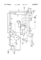
- FIG. 1 is a schematic representation of an embodiment of the invention incorporated into a powerstation
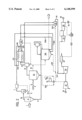
- FIG. 2 is a schematic representation of a second embodiment of the invention incorporated into a powerstation.
- the process and apparatus of the invention are usable with high rank coals. While high rank coals do not have a large amount of water bonded with their structure, water may be added to the process either with the coal or separately to make up the necessary moisture content.
- High rank coals are often fed as a paste or slurry having a high water content and such pastes or slurries are usable with the invention.
- reference to solid carbonaceous feed material having a high moisture content is intended to include not only low rank coals with a large amount of bonded water but also any low moisture content carbonaceous material including high rank coals with a low structural water content and water added separately or with the material.
- raw low rank or moist coal 1 is fed to a pressurised drier 2 where it is contacted with a flow of hot flue gas 3 from a combustor 4.
- the hot flue gas 3 preferably enters the drier at a temperature above 700° C. and preferably about 860° C. and has an oxygen content of less than nominally 10 wt % but in practice may be as low as is practicable to maintain complete combustion in the combustor to reduce the risk of the raw coal igniting once the moisture content in the coal is sufficiently reduced.
- the coal in the pressurized drier 2 which is at a pressure of about 15 bar to suit the pressure developed by a typical gas turbine compressor, is dried in the flow of hot flue gas.
- the drier is preferably an entrained flow type or it may be a fluidised bed or other suitable type.
- the coal leaving the drier 2 has a moisture content nominally in the range of 12% to 20 wt % and the flue gas stream after drying the coal has a temperature of about 200° C.
- the entrained dried coal and flue gas stream 3a After leaving the pressurised drier 2, the entrained dried coal and flue gas stream 3a then passes into a gas/solid separator 5 such as a cyclone where the dried coal 6a is separated from the cooled flue gas 7.
- a gas/solid separator 5 such as a cyclone
- the flue gas in one option is passed through a dehumidifier and moisture separator 40 before being transferred to fuel gas cooler 8.
- the flue gas may be dehumidified, for example, by cooling the gas stream with condensate A from the steam turbine in a heat exchanger. The heat thus extracted is usefully utilised for heating feed water B.
- the gas temperature that can be achieved at the turbine inlet is thus increased and the cycle efficiency is greater than can be obtained without dehumidification.
- the mass flow through the turbine rotor in excess of the mass flow of air supplied by the turbine compressor, due to moisture evaporated from the coal can be controlled to avoid limitations imposed by compressor surge considerations.
- any additional mass flow through the turbine rotor over the mass flow of air supplied from the turbine compressor has a very beneficial effect on gas turbine performance.
- gas turbines are available with adequate surge margins, there may be advantages in a system without dehumidification and hence operating at lower turbine inlet temperatures because the efficiency penalty incurred is likely to be small. These advantages relate to avoiding the complexities associated with the collection and treatment of the water condensed from the flue gas.
- the dried coal 6a leaving the gas/solid separator 5 is then admitted to a pressurised carboniser 10 via a screw feeder 9 or suitable solid feeder.
- the carboniser 10 is an air blown fluidised bed gasifier which is fluidised with pressurised air 10a produced by turbine compressor 12 and booster compressor 14. Air is drawn from the atmosphere into compressor 12 and then passed to booster compressor 14 to bring the air to the required pressure before passing through ducting to the carboniser 10.
- the pressure in the carboniser may vary from slightly greater then the pressure developed by the turbine compressor to, say, 10 bar greater.
- the oxygen in the air partially combusts the dried coal in the carboniser 10 to provide the heat for gasification to produce a hot fuel gas 18 and a solid residual char 16.
- the proportioning of fuel gas (including any tars) and char will be a function of the coal type and carboniser conditions.
- the degree of gasification in the carboniser 10 is dependent on such factors as temperature in the carboniser, residence time for the solid material and the gasification agent.
- the expected char yield may be typically in the range of 5 wt % to 40 wt %.
- the carboniser char yield should be controlled and adjusted in consideration of the energy requirements of the fuel gas 18 to achieve a high gas turbine inlet temperature.
- the char 16 is removed from the carboniser 10 and fed to the combustor 4 in a screw feeder 30 or suitable solid feeder.
- the combustor 4 is preferably a pressurised fluid bed combustor which is fluidised by air 4a supplied by compressor 12.
- the oxygen level in the flue gas 3 to be supplied to the driver 2 should be controlled to a sufficiently low level to avoid the possibility of an explosion and thereby ensure safe operation of the drier.
- the oxygen level is to be maintained below a level of less than nominally 10 wt % but in practice may be as low as practicable to maintain complete combustion in the combustor.
- the oxygen level of the flue gas 3 is able to be independently controlled by the admission of carbonaceous material 50 directly into the combustor 4.
- Carbonaceous material 50 which is preferably the same high moisture content carbonaceous material fed into pressurised drier 2 may be supplied to the combustor 4.
- cooled flue gas 49 can be recirculated by recirculation compressor 37 to the inlet of the combustor which will result in a higher cycle efficiency.
- the potential of the flue gas to dry the carbonaceous material in the drier is dependent on the mass flow, and the temperature and humidity of the flue gas entering combustor 4.
- the fuel gas 18 from the carboniser 10 is passed into a gas/solid separator 19 and cooled by the flue gas to a temperature nominally below 600° C.
- the flue gas 21 is then cooled either by indirect cooling in a heat exchanger 8 or by direct mixing with flue gas 7. Since direct mixing has the effect of diluting the fuel gas and potentially reducing the calorific value of the gas mixture below a level which is able to provide stable combustion in a topping combustor 20, indirect cooling in a heat exchanger 8 is preferred.
- the volatilised alkali metals such as sodium are condensed from the fuel gas stream 21 and collect on the entrained ash particles for removal with the particulates in a hot gas filter 22.
- the alkali concentration in the resulting cooled fuel gas 48 is expected to be below the currently acceptable limit of 24 ppb.
- the fuel gas 48 After passing through the hot gas filter 22, the fuel gas 48 is passed to a topping combustor 20 where the fuel gas is combusted in the presence of the flue gas 23 and air 20a supplied by compressor 12.
- the hot turbine feed gases 45 are then used to drive the rotor of the gas turbine 24 which generates electric power through generator 25 and the gas turbine powers compressor 12.
- the efficiency of the power generation can be marginly improved either by:
- a heat recovery circuit is arranged to operate in conjunction with the combustor to drive high pressure steam turbine 27 and intermediate/low pressure steam turbine 28.
- the heat from the exhaust of gas turbine 24 is used to heat circulating feed water B in an economiser 31.
- Steam raising and superheating of the steam to drive the high pressure steam turbine 27 is accomplished in a first heating stage 34 in the combustor 4 and reheating of the steam to drive the intermediate/low pressure steam turbine is carried out in a second heating stage 35 in the combustor 4.
- the high pressure steam turbine 27 is coupled to an intermediate/low pressure steam turbine 28 to generate electrical power through generator 26.
- the steam from the intermediate/low pressure steam turbine is condensed in condenser 36 and the condensate A fed to dehumidifier and moisture separator 40.
- the condensate A may be used to cool and condense moisture 47 from the flue gas stream 7.
- the heated condensate B may be returned to the feed via deaerator 46.
- the stoichiometric combustion temperature in the topping combustor 20 will be less than the maximum allowable turbine inlet temperature, resulting in an efficiency less than the capability of the gas turbine. This reduction, however, is largely compensated by the increased output and hence efficiency due to the evaporated coal water being expanded through the turbine.
- steam cooling or the use of ceramic blading will result in more of the air of the gas turbine compressor being available for combustion, as the air for cooling and sealing the gas turbine bypasses the combustor.
- the estimated performance of the A-PFBC fed with raw coal is as follows assuming the use of a supercritical steam cycle.
- FIG. 2 A further embodiment that, where applicable, offers potentially significant advantages is shown in FIG. 2. Where equipment identical to the embodiment of FIG. 1 is referenced, the numbering and description in regard to FIG. 1 is the same.
- This embodiment is applicable, in particular, for carbonaceous materials for which there has been a high carbon conversion in the carboniser and which have a high moisture content.
- the heat liberated from burning the char 16 in the pressurised combustor 104 is used only to generate hot flue gas 3 which in turn dries the feed coal 1.
- the input streams to the pressurised fluid bed combustor 104 are char 16, combustion air 108 and recirculated flue gas 106 obtained from downstream of the drier 2 and the flue gas cooler 107.
- the temperature of the flue gas would be controlled to about 860° C. and the mass flow would be adjusted by controlling the flow of recirculated flue gas via compressor 108. If there is insufficient heat generated from the combustion of the char, the balance can be provided by diverting a stream 109a of fuel gas from the carboniser stream 21 and burning this with the char 16 in the pressurised combustor 104.
- a char yield of approximately 13.5% by weight of dried coal would provide sufficient heat to dry the coal to a moisture content of 20%.
- the fuel gas cooler 107 is arranged with the fuel gas 21 and flue gas 106, 109 in counter-flow, which enables the fuel gas 21 to be cooled from a temperature of about 860° C. to a relatively low temperature of about 350° C., by heat exchange with the flue gas 106, 109 from the drier 2 at about 180° C.
- a control valve (not shown) in the fuel gas line 21 can therefore be used to effect control of a gas turbine. Because of temperature considerations, the compressor 108 for recirculating part of the flue gas 106 to pressurised combustor 104 can be positioned upstream of the fuel gas cooler 107 where the gas temperature is low.
- This arrangement is more efficient than the other embodiment as the whole of the power is generated from a high efficiency combined cycle gas turbine, i.e. a gas turbine and its associated waste heat boiler and steam turbine.
- a high efficiency combined cycle gas turbine i.e. a gas turbine and its associated waste heat boiler and steam turbine.
- This compares with a combination of combined cycle gas turbine and high pressure steam cycle from the embodiment of FIG. 1.
- the maximum gas temperature achievable is higher than in the systems that transfer part of the coal energy to steam in a pressurised fluid bed boiler 104. This can be important for high moisture coals as the maximum temperature that can be achieved at close to stoichiometric conditions may be less than the allowable turbine inlet temperature.
- this process is also applicable to lower moisture content coals including high rank coals and other carbonaceous materials which may have added water. Water may be added to these materials for example to produce a past or slurry which may be fed directly into the pressurised drier 2. Such direct feeding systems are in use in some current gasifier and PFBC systems.
- one of the problems previously encountered using high moisture content carbonaceous materials is the need to include a separate predrying step and the removal of alkali metal species which are more prevalent in high moisture content carbonaceous materials such as brown coal than in high rank coals such as bituminous coal.
- the present invention provides an integrated process for the drying and gasification of high moisture content solid carbonaceous material and the combustion of the char residue which results in very high carbon conversion and a high efficiency when compared to other processes which use high moisture carbonaceous materials.
- the present invention is able to utilise the drying process to condense the alkali species volatilised during combustion and gasification of the high moisture content solid carbonaceous material.
- the present invention may allow the use of a turbine control valve (not shown) immediately upstream of the topping combustor 20. Although this will require operation of the carboniser only at a higher pressure, it provides direct and more immediate control of the gas turbine 24.
- boiler heat transfer surface provided the heat required for drying is arranged to be greater than or equal to the heat generated from burning the char.
- the present invention provides the opportunity and potential for producing power plants with lower capital costs.
Landscapes
- Chemical & Material Sciences (AREA)
- Engineering & Computer Science (AREA)
- Combustion & Propulsion (AREA)
- Oil, Petroleum & Natural Gas (AREA)
- Organic Chemistry (AREA)
- Chemical Kinetics & Catalysis (AREA)
- General Chemical & Material Sciences (AREA)
- Solid Fuels And Fuel-Associated Substances (AREA)
- Engine Equipment That Uses Special Cycles (AREA)
- Treatment Of Sludge (AREA)
Applications Claiming Priority (2)
| Application Number | Priority Date | Filing Date | Title |
|---|---|---|---|
| AUPO9100A AUPO910097A0 (en) | 1997-09-10 | 1997-09-10 | Power generation process and apparatus |
| AUPO9100 | 1997-09-10 |
Publications (1)
| Publication Number | Publication Date |
|---|---|
| US6148599A true US6148599A (en) | 2000-11-21 |
Family
ID=3803385
Family Applications (1)
| Application Number | Title | Priority Date | Filing Date |
|---|---|---|---|
| US09/114,432 Expired - Fee Related US6148599A (en) | 1997-09-10 | 1998-07-13 | Process and apparatus for gasifying solid carbonaceous material having a high moisture content |
Country Status (6)
| Country | Link |
|---|---|
| US (1) | US6148599A (fr) |
| EP (1) | EP1027408A4 (fr) |
| CN (1) | CN1277628A (fr) |
| AU (1) | AUPO910097A0 (fr) |
| ID (1) | ID23881A (fr) |
| WO (1) | WO1999013025A1 (fr) |
Cited By (24)
| Publication number | Priority date | Publication date | Assignee | Title |
|---|---|---|---|---|
| US20070023549A1 (en) * | 2005-04-29 | 2007-02-01 | French Robert R | Method to transform bulk material |
| US20090158645A1 (en) * | 2007-08-01 | 2009-06-25 | French Robert R | Methods of Producing Water-Resistant Solid Fuels |
| FR2925915A1 (fr) * | 2007-12-26 | 2009-07-03 | Total France Sa | Procede et chaine de traitement pour la conversion thermochimique par gazeification d'une charge humide de materiau biologique, notamment de la biomasse ou du charbon. |
| US20090257941A1 (en) * | 2008-04-14 | 2009-10-15 | Rudberg Donald A | Coal/Coke/Heavy Residual Oil Boiler With Sulfur And Carbon Dioxide Capture And Recovery |
| US20100012006A1 (en) * | 2008-07-15 | 2010-01-21 | Covanta Energy Corporation | System and method for gasification-combustion process using post combustor |
| US7669349B1 (en) * | 2004-03-04 | 2010-03-02 | TD*X Associates LP | Method separating volatile components from feed material |
| US20100288171A1 (en) * | 2009-05-18 | 2010-11-18 | Covanta Energy Corporation | Gasification combustion system |
| US20100288173A1 (en) * | 2009-05-18 | 2010-11-18 | Covanta Energy Corporation | Gasification combustion system |
| US20100294179A1 (en) * | 2009-05-18 | 2010-11-25 | Covanta Energy Corporation | Gasification combustion system |
| WO2011022767A1 (fr) * | 2009-08-25 | 2011-03-03 | Monash University | Procédé et système pour sécher une matière carbonée |
| US7987613B2 (en) * | 2004-10-12 | 2011-08-02 | Great River Energy | Control system for particulate material drying apparatus and process |
| US20110197797A1 (en) * | 2010-02-18 | 2011-08-18 | Chavond-Barry Engineering Corp. | Method and apparatus for efficient production of activated carbon |
| US8062410B2 (en) | 2004-10-12 | 2011-11-22 | Great River Energy | Apparatus and method of enhancing the quality of high-moisture materials and separating and concentrating organic and/or non-organic material contained therein |
| US8523963B2 (en) | 2004-10-12 | 2013-09-03 | Great River Energy | Apparatus for heat treatment of particulate materials |
| US8579999B2 (en) | 2004-10-12 | 2013-11-12 | Great River Energy | Method of enhancing the quality of high-moisture materials using system heat sources |
| US8651282B2 (en) | 2004-10-12 | 2014-02-18 | Great River Energy | Apparatus and method of separating and concentrating organic and/or non-organic material |
| US20140259882A1 (en) * | 2013-03-15 | 2014-09-18 | General Electric Company | Mixture and apparatus for blending non-aqueous slurries |
| US8997664B2 (en) | 2009-05-18 | 2015-04-07 | Covanta Energy, Llc | Gasification combustion system |
| US9260301B2 (en) | 2011-05-09 | 2016-02-16 | Hrl Treasury (Idgcc) Pty Ltd | Integrated drying gasification |
| EP3098549A1 (fr) * | 2015-05-26 | 2016-11-30 | General Electric Technology GmbH | Séchage de lignite avec un circuit de récupération de chaleur |
| US9527022B2 (en) * | 2012-06-08 | 2016-12-27 | Uop Llc | Method and apparatus for producing pyrolysis oil having improved stability |
| US9835056B2 (en) | 2015-05-26 | 2017-12-05 | General Electric Technology Gmbh | Lignite drying integration with a water/steam power cycle |
| US9944875B2 (en) | 2015-05-26 | 2018-04-17 | General Electric Technology Gmbh | Lignite drying in a lignite fired power plant with a heat pump |
| US10392575B2 (en) | 2015-05-26 | 2019-08-27 | General Electric Company | Lignite drying with closed loop heat pump |
Families Citing this family (8)
| Publication number | Priority date | Publication date | Assignee | Title |
|---|---|---|---|---|
| CA2433965C (fr) * | 2001-01-10 | 2012-01-03 | Shell Internationale Research Maatschappij B.V. | Procede de production d'electricite et de produits lumineux convertis thermiquement |
| AUPS335902A0 (en) * | 2002-07-03 | 2002-07-25 | Wesfarmers Premier Coal Limited | Coal drying and charring process |
| CN1323142C (zh) * | 2005-08-24 | 2007-06-27 | 太原理工大学 | 复合循环流化床煤气化方法及设备 |
| NZ579390A (en) * | 2007-02-16 | 2012-03-30 | Corky S Carbon And Comb Pty Ltd | Drying and gasification process |
| DE102008036734A1 (de) * | 2008-08-07 | 2010-02-18 | Spot Spirit Of Technology Ag | Verfahren und Vorrichtung zur Herstellung von Energie, DME (Dimethylether und Bio-Silica unter Einsatz von CO2-neutralen biogenen reaktiven und reaktionsträgen Einsatzstoffen |
| CN102453551A (zh) * | 2010-10-14 | 2012-05-16 | 通用电气公司 | 集成干燥和气化固体燃料颗粒的系统及方法 |
| FR3043080B1 (fr) * | 2015-11-04 | 2021-01-08 | Haffner Energy | Procede de production de gaz synthetique hypergaz |
| CN117342924A (zh) * | 2023-08-01 | 2024-01-05 | 浙江巍华新材料股份有限公司 | 一种间氟三氟甲苯的制备方法 |
Citations (4)
| Publication number | Priority date | Publication date | Assignee | Title |
|---|---|---|---|---|
| US3309780A (en) * | 1962-04-09 | 1967-03-21 | Phillips Petroleum Co | Process and apparatus for drying wet particulate solids |
| US4150953A (en) * | 1978-05-22 | 1979-04-24 | General Electric Company | Coal gasification power plant and process |
| US5171406A (en) * | 1989-04-26 | 1992-12-15 | Western Research Institute | Fluidized bed selective pyrolysis of coal |
| US5953899A (en) * | 1995-02-09 | 1999-09-21 | Fluor Daniel, Inc. | Integrated drying of feedstock feed to integrated combined-cycle gasification plant |
Family Cites Families (14)
| Publication number | Priority date | Publication date | Assignee | Title |
|---|---|---|---|---|
| GB207809A (fr) * | 1922-11-30 | 1925-04-23 | Kohlenveredlung Gesellschaft Mit Beschraenkter Haftung | |
| US3817723A (en) * | 1972-03-23 | 1974-06-18 | Secretary | Two-stage gasification of pretreated coal |
| US4211606A (en) * | 1975-08-19 | 1980-07-08 | Chikul Olga S | Method for thermal processing bitumen-containing materials and device for realization of same |
| US4105536A (en) * | 1976-04-23 | 1978-08-08 | Morrell Jacque C | Processes including the production of non-congealing shale oil from oil shales |
| DE2738442B2 (de) * | 1977-08-26 | 1979-10-18 | Didier Engineering Gmbh, 4300 Essen | Verfahren bzw. Anlage zur Nutzung der fühlbaren Kokswärme in einer Verkokungsanlage |
| US4158948A (en) * | 1978-08-16 | 1979-06-26 | Texaco Inc. | Conversion of solid fuels into fluid fuels |
| DD143712A3 (de) * | 1978-08-18 | 1980-09-10 | Manfred Schingnitz | Verfahren zur bereitstellung von prozessdampf in integrierten braunkohleveredlungsanlagen |
| NL8201715A (nl) * | 1982-04-26 | 1983-11-16 | Shell Int Research | Werkwijze voor het vergassen van een vaste koolstofhoudende brandstof. |
| GB2134921A (en) * | 1983-02-14 | 1984-08-22 | Combustion Eng | High temperature pyrolysis process |
| IL104509A (en) * | 1992-01-29 | 1999-10-28 | Ormat Inc | Method and means for producing flammable gases from solid fuels with low caloric value |
| CZ43993A3 (en) * | 1992-03-25 | 1994-02-16 | Ormat Ind Ltd | Process for producing heating gas from a low-grade solid fuel, and apparatus for making the same |
| CA2134871C (fr) * | 1992-05-08 | 2001-12-18 | Terence R. Johnson | Procede integre et appareillage pour le sechage et la gazeification de combustibles carbones |
| DE19503438A1 (de) * | 1995-02-03 | 1996-08-08 | Metallgesellschaft Ag | Verfahren zum Vergasen von brennbare Bestandteile enthaltendem Material in der zirkulierenden Wirbelschicht |
| DE69624073T2 (de) * | 1995-11-28 | 2003-08-14 | Ebara Corp., Tokio/Tokyo | Verfahren und Vorrichtung zur Behandlung von Abfällen mittels Vergasung |
-
1997
- 1997-09-10 AU AUPO9100A patent/AUPO910097A0/en not_active Abandoned
-
1998
- 1998-07-13 US US09/114,432 patent/US6148599A/en not_active Expired - Fee Related
- 1998-08-03 CN CN98810486A patent/CN1277628A/zh active Pending
- 1998-08-03 ID IDW20000636A patent/ID23881A/id unknown
- 1998-08-03 EP EP98937345A patent/EP1027408A4/fr not_active Withdrawn
- 1998-08-03 WO PCT/AU1998/000610 patent/WO1999013025A1/fr not_active Ceased
Patent Citations (4)
| Publication number | Priority date | Publication date | Assignee | Title |
|---|---|---|---|---|
| US3309780A (en) * | 1962-04-09 | 1967-03-21 | Phillips Petroleum Co | Process and apparatus for drying wet particulate solids |
| US4150953A (en) * | 1978-05-22 | 1979-04-24 | General Electric Company | Coal gasification power plant and process |
| US5171406A (en) * | 1989-04-26 | 1992-12-15 | Western Research Institute | Fluidized bed selective pyrolysis of coal |
| US5953899A (en) * | 1995-02-09 | 1999-09-21 | Fluor Daniel, Inc. | Integrated drying of feedstock feed to integrated combined-cycle gasification plant |
Cited By (37)
| Publication number | Priority date | Publication date | Assignee | Title |
|---|---|---|---|---|
| US7669349B1 (en) * | 2004-03-04 | 2010-03-02 | TD*X Associates LP | Method separating volatile components from feed material |
| US8020313B2 (en) | 2004-03-04 | 2011-09-20 | TD*X Associates LP | Method and apparatus for separating volatile components from feed material |
| US8651282B2 (en) | 2004-10-12 | 2014-02-18 | Great River Energy | Apparatus and method of separating and concentrating organic and/or non-organic material |
| US8523963B2 (en) | 2004-10-12 | 2013-09-03 | Great River Energy | Apparatus for heat treatment of particulate materials |
| US7987613B2 (en) * | 2004-10-12 | 2011-08-02 | Great River Energy | Control system for particulate material drying apparatus and process |
| US8062410B2 (en) | 2004-10-12 | 2011-11-22 | Great River Energy | Apparatus and method of enhancing the quality of high-moisture materials and separating and concentrating organic and/or non-organic material contained therein |
| US8579999B2 (en) | 2004-10-12 | 2013-11-12 | Great River Energy | Method of enhancing the quality of high-moisture materials using system heat sources |
| US8453953B2 (en) | 2005-04-29 | 2013-06-04 | Gtl Energy Holdings Pty Limited | Method to transform bulk material |
| US20070023549A1 (en) * | 2005-04-29 | 2007-02-01 | French Robert R | Method to transform bulk material |
| US7913939B2 (en) * | 2005-04-29 | 2011-03-29 | GTL Energy, Ltd. | Method to transform bulk material |
| US20110167715A1 (en) * | 2005-04-29 | 2011-07-14 | Gtl Energy, Ltd | Method to transform bulk material |
| US9499756B2 (en) | 2007-08-01 | 2016-11-22 | Gtl Energy Holdings Pty Limited | Roll press |
| US20090158645A1 (en) * | 2007-08-01 | 2009-06-25 | French Robert R | Methods of Producing Water-Resistant Solid Fuels |
| US8673030B2 (en) | 2007-08-01 | 2014-03-18 | Gtl Energy Holdings Pty Limited | Methods of producing water-resistant solid fuels |
| WO2009081082A3 (fr) * | 2007-12-26 | 2010-01-07 | Total Raffinage Marketing | Procede et chaine de traitement pour la conversion thermochimique par gazeification d'une charge humide de materiau biologique |
| US9074150B2 (en) | 2007-12-26 | 2015-07-07 | Total Raffinage Marketing | Treatment chain and process for the thermochemical conversion of a wet feed of biological material by gasification |
| FR2925915A1 (fr) * | 2007-12-26 | 2009-07-03 | Total France Sa | Procede et chaine de traitement pour la conversion thermochimique par gazeification d'une charge humide de materiau biologique, notamment de la biomasse ou du charbon. |
| WO2009131849A1 (fr) * | 2008-04-14 | 2009-10-29 | Plasma Energy Technologies Inc. | Chaudière de combustion de charbon/coke/huile résiduelle lourde, avec capture et récupération de soufre et de dioxyde de carbone |
| US8084010B2 (en) | 2008-04-14 | 2011-12-27 | Plasma Energy Technologies Inc. | Coal/coke/heavy residual oil boiler with sulfur and carbon dioxide capture and recovery |
| US20090257941A1 (en) * | 2008-04-14 | 2009-10-15 | Rudberg Donald A | Coal/Coke/Heavy Residual Oil Boiler With Sulfur And Carbon Dioxide Capture And Recovery |
| US20100012006A1 (en) * | 2008-07-15 | 2010-01-21 | Covanta Energy Corporation | System and method for gasification-combustion process using post combustor |
| US20100288173A1 (en) * | 2009-05-18 | 2010-11-18 | Covanta Energy Corporation | Gasification combustion system |
| US20100294179A1 (en) * | 2009-05-18 | 2010-11-25 | Covanta Energy Corporation | Gasification combustion system |
| US20100288171A1 (en) * | 2009-05-18 | 2010-11-18 | Covanta Energy Corporation | Gasification combustion system |
| US8701573B2 (en) * | 2009-05-18 | 2014-04-22 | Convanta Energy Corporation | Gasification combustion system |
| US8707875B2 (en) | 2009-05-18 | 2014-04-29 | Covanta Energy Corporation | Gasification combustion system |
| US8997664B2 (en) | 2009-05-18 | 2015-04-07 | Covanta Energy, Llc | Gasification combustion system |
| WO2011022767A1 (fr) * | 2009-08-25 | 2011-03-03 | Monash University | Procédé et système pour sécher une matière carbonée |
| US20110197797A1 (en) * | 2010-02-18 | 2011-08-18 | Chavond-Barry Engineering Corp. | Method and apparatus for efficient production of activated carbon |
| US9260301B2 (en) | 2011-05-09 | 2016-02-16 | Hrl Treasury (Idgcc) Pty Ltd | Integrated drying gasification |
| US9527022B2 (en) * | 2012-06-08 | 2016-12-27 | Uop Llc | Method and apparatus for producing pyrolysis oil having improved stability |
| US20140259882A1 (en) * | 2013-03-15 | 2014-09-18 | General Electric Company | Mixture and apparatus for blending non-aqueous slurries |
| EP3098549A1 (fr) * | 2015-05-26 | 2016-11-30 | General Electric Technology GmbH | Séchage de lignite avec un circuit de récupération de chaleur |
| US9835056B2 (en) | 2015-05-26 | 2017-12-05 | General Electric Technology Gmbh | Lignite drying integration with a water/steam power cycle |
| US9944874B2 (en) | 2015-05-26 | 2018-04-17 | General Electric Technology Gmbh | Lignite drying with a heat recovery circuit |
| US9944875B2 (en) | 2015-05-26 | 2018-04-17 | General Electric Technology Gmbh | Lignite drying in a lignite fired power plant with a heat pump |
| US10392575B2 (en) | 2015-05-26 | 2019-08-27 | General Electric Company | Lignite drying with closed loop heat pump |
Also Published As
| Publication number | Publication date |
|---|---|
| WO1999013025A1 (fr) | 1999-03-18 |
| EP1027408A1 (fr) | 2000-08-16 |
| AUPO910097A0 (en) | 1997-10-02 |
| ID23881A (id) | 2000-05-25 |
| CN1277628A (zh) | 2000-12-20 |
| EP1027408A4 (fr) | 2003-03-12 |
Similar Documents
| Publication | Publication Date | Title |
|---|---|---|
| WO1999013025A1 (fr) | Procede et dispositif servant a gazeifier un materiau carbone solide | |
| US4492085A (en) | Gas turbine power plant | |
| RU2134713C1 (ru) | Способ газификации порошкообразного твердого углеродистого топлива и устройство для его осуществления, интегрированный способ получения энергии | |
| US5685138A (en) | Integrated drying of feedstock feed to IGCC plant | |
| EP0602795B1 (fr) | Système de combustion à lit fluidisé et procédé de combustion à lit fluidisé | |
| US6141796A (en) | Use of carbonaceous fuels | |
| US4468923A (en) | Process and plant for generating electrical energy | |
| US5655466A (en) | Method and configuration for facilitating the fuel feed into a pressurized space | |
| Paisley et al. | Biomass gasification for gas turbine-based power generation | |
| US5000099A (en) | Combination of fuels conversion and pressurized wet combustion | |
| JPS63195333A (ja) | 含水燃料を燃焼するガスタービン出力装置及びこのガスタービン出力装置における含水燃料の熱エネルギ回収方法 | |
| AU645255B2 (en) | Process for generating electric power | |
| US5822974A (en) | Hybrid biomass and natural gas/oil power generation system | |
| EP0707137B1 (fr) | Méthode et appareil pour produire de l'énergie électrique utilisant une chaudière et une turbine à gaz alimentées par gazéification | |
| CA1105703A (fr) | Installation d'utilisation de l'energie residuelle des combustibles fossiles solides, particulierement de ceux a forte teneur en elements inertes et du charbon bitumineux | |
| AU740099B2 (en) | Process and apparatus for gasifying solid carbonaceous material | |
| JP4089079B2 (ja) | 廃棄物処理方法及び廃棄物処理システム | |
| Bentzen et al. | Upscale of the two-stage gasification process | |
| JP2000283434A (ja) | 廃棄物処理方法及び廃棄物処理システム | |
| JP4089080B2 (ja) | 廃棄物処理方法及び廃棄物処理システム | |
| CN224199333U (zh) | 一种生物质气化炉耦合火电厂的系统 | |
| JPH07208704A (ja) | 石炭ガス化発電装置 | |
| WO2011022767A1 (fr) | Procédé et système pour sécher une matière carbonée | |
| JP2000283433A (ja) | 廃棄物処理方法及び廃棄物処理システム | |
| Holmes et al. | Synthetic Fuel from Wood Using Steam and Air |
Legal Events
| Date | Code | Title | Description |
|---|---|---|---|
| AS | Assignment |
Owner name: GENERATION TECHNOLOGY RESEARCH PTY. LTD., AUSTRALI Free format text: ASSIGNMENT OF ASSIGNORS INTEREST;ASSIGNORS:MCINTOSH, MALCOLM J.;BHATTACHARYA, SANKAR;REEL/FRAME:009549/0936 Effective date: 19980728 |
|
| FPAY | Fee payment |
Year of fee payment: 4 |
|
| FEPP | Fee payment procedure |
Free format text: PAYOR NUMBER ASSIGNED (ORIGINAL EVENT CODE: ASPN); ENTITY STATUS OF PATENT OWNER: LARGE ENTITY |
|
| REMI | Maintenance fee reminder mailed | ||
| LAPS | Lapse for failure to pay maintenance fees | ||
| STCH | Information on status: patent discontinuation |
Free format text: PATENT EXPIRED DUE TO NONPAYMENT OF MAINTENANCE FEES UNDER 37 CFR 1.362 |
|
| FP | Lapsed due to failure to pay maintenance fee |
Effective date: 20081121 |