US6148613A - Reversing flow catalytic converter for internal combustion engine - Google Patents
Reversing flow catalytic converter for internal combustion engine Download PDFInfo
- Publication number
- US6148613A US6148613A US09/404,019 US40401999A US6148613A US 6148613 A US6148613 A US 6148613A US 40401999 A US40401999 A US 40401999A US 6148613 A US6148613 A US 6148613A
- Authority
- US
- United States
- Prior art keywords
- valve
- exhaust
- catalytic converter
- container
- cavity
- Prior art date
- Legal status (The legal status is an assumption and is not a legal conclusion. Google has not performed a legal analysis and makes no representation as to the accuracy of the status listed.)
- Expired - Fee Related
Links
Images

Classifications
-
- F—MECHANICAL ENGINEERING; LIGHTING; HEATING; WEAPONS; BLASTING
- F01—MACHINES OR ENGINES IN GENERAL; ENGINE PLANTS IN GENERAL; STEAM ENGINES
- F01N—GAS-FLOW SILENCERS OR EXHAUST APPARATUS FOR MACHINES OR ENGINES IN GENERAL; GAS-FLOW SILENCERS OR EXHAUST APPARATUS FOR INTERNAL-COMBUSTION ENGINES
- F01N3/00—Exhaust or silencing apparatus having means for purifying, rendering innocuous, or otherwise treating exhaust
- F01N3/08—Exhaust or silencing apparatus having means for purifying, rendering innocuous, or otherwise treating exhaust for rendering innocuous
- F01N3/10—Exhaust or silencing apparatus having means for purifying, rendering innocuous, or otherwise treating exhaust for rendering innocuous by thermal or catalytic conversion of noxious components of exhaust
- F01N3/18—Exhaust or silencing apparatus having means for purifying, rendering innocuous, or otherwise treating exhaust for rendering innocuous by thermal or catalytic conversion of noxious components of exhaust characterised by methods of operation; Control
- F01N3/20—Exhaust or silencing apparatus having means for purifying, rendering innocuous, or otherwise treating exhaust for rendering innocuous by thermal or catalytic conversion of noxious components of exhaust characterised by methods of operation; Control specially adapted for catalytic conversion
- F01N3/2093—Periodically blowing a gas through the converter, e.g. in a direction opposite to exhaust gas flow or by reversing exhaust gas flow direction
-
- F—MECHANICAL ENGINEERING; LIGHTING; HEATING; WEAPONS; BLASTING
- F01—MACHINES OR ENGINES IN GENERAL; ENGINE PLANTS IN GENERAL; STEAM ENGINES
- F01N—GAS-FLOW SILENCERS OR EXHAUST APPARATUS FOR MACHINES OR ENGINES IN GENERAL; GAS-FLOW SILENCERS OR EXHAUST APPARATUS FOR INTERNAL-COMBUSTION ENGINES
- F01N13/00—Exhaust or silencing apparatus characterised by constructional features
- F01N13/009—Exhaust or silencing apparatus characterised by constructional features having two or more separate purifying devices arranged in series
- F01N13/0097—Exhaust or silencing apparatus characterised by constructional features having two or more separate purifying devices arranged in series the purifying devices are arranged in a single housing
-
- F—MECHANICAL ENGINEERING; LIGHTING; HEATING; WEAPONS; BLASTING
- F01—MACHINES OR ENGINES IN GENERAL; ENGINE PLANTS IN GENERAL; STEAM ENGINES
- F01N—GAS-FLOW SILENCERS OR EXHAUST APPARATUS FOR MACHINES OR ENGINES IN GENERAL; GAS-FLOW SILENCERS OR EXHAUST APPARATUS FOR INTERNAL-COMBUSTION ENGINES
- F01N3/00—Exhaust or silencing apparatus having means for purifying, rendering innocuous, or otherwise treating exhaust
- F01N3/08—Exhaust or silencing apparatus having means for purifying, rendering innocuous, or otherwise treating exhaust for rendering innocuous
- F01N3/10—Exhaust or silencing apparatus having means for purifying, rendering innocuous, or otherwise treating exhaust for rendering innocuous by thermal or catalytic conversion of noxious components of exhaust
- F01N3/18—Exhaust or silencing apparatus having means for purifying, rendering innocuous, or otherwise treating exhaust for rendering innocuous by thermal or catalytic conversion of noxious components of exhaust characterised by methods of operation; Control
- F01N3/20—Exhaust or silencing apparatus having means for purifying, rendering innocuous, or otherwise treating exhaust for rendering innocuous by thermal or catalytic conversion of noxious components of exhaust characterised by methods of operation; Control specially adapted for catalytic conversion
-
- F—MECHANICAL ENGINEERING; LIGHTING; HEATING; WEAPONS; BLASTING
- F01—MACHINES OR ENGINES IN GENERAL; ENGINE PLANTS IN GENERAL; STEAM ENGINES
- F01N—GAS-FLOW SILENCERS OR EXHAUST APPARATUS FOR MACHINES OR ENGINES IN GENERAL; GAS-FLOW SILENCERS OR EXHAUST APPARATUS FOR INTERNAL-COMBUSTION ENGINES
- F01N3/00—Exhaust or silencing apparatus having means for purifying, rendering innocuous, or otherwise treating exhaust
- F01N3/08—Exhaust or silencing apparatus having means for purifying, rendering innocuous, or otherwise treating exhaust for rendering innocuous
- F01N3/10—Exhaust or silencing apparatus having means for purifying, rendering innocuous, or otherwise treating exhaust for rendering innocuous by thermal or catalytic conversion of noxious components of exhaust
- F01N3/24—Exhaust or silencing apparatus having means for purifying, rendering innocuous, or otherwise treating exhaust for rendering innocuous by thermal or catalytic conversion of noxious components of exhaust characterised by constructional aspects of converting apparatus
- F01N3/28—Construction of catalytic reactors
- F01N3/2882—Catalytic reactors combined or associated with other devices, e.g. exhaust silencers or other exhaust purification devices
-
- F—MECHANICAL ENGINEERING; LIGHTING; HEATING; WEAPONS; BLASTING
- F01—MACHINES OR ENGINES IN GENERAL; ENGINE PLANTS IN GENERAL; STEAM ENGINES
- F01N—GAS-FLOW SILENCERS OR EXHAUST APPARATUS FOR MACHINES OR ENGINES IN GENERAL; GAS-FLOW SILENCERS OR EXHAUST APPARATUS FOR INTERNAL-COMBUSTION ENGINES
- F01N2250/00—Combinations of different methods of purification
- F01N2250/12—Combinations of different methods of purification absorption or adsorption, and catalytic conversion
-
- F—MECHANICAL ENGINEERING; LIGHTING; HEATING; WEAPONS; BLASTING
- F01—MACHINES OR ENGINES IN GENERAL; ENGINE PLANTS IN GENERAL; STEAM ENGINES
- F01N—GAS-FLOW SILENCERS OR EXHAUST APPARATUS FOR MACHINES OR ENGINES IN GENERAL; GAS-FLOW SILENCERS OR EXHAUST APPARATUS FOR INTERNAL-COMBUSTION ENGINES
- F01N2290/00—Movable parts or members in exhaust systems for other than for control purposes
-
- Y—GENERAL TAGGING OF NEW TECHNOLOGICAL DEVELOPMENTS; GENERAL TAGGING OF CROSS-SECTIONAL TECHNOLOGIES SPANNING OVER SEVERAL SECTIONS OF THE IPC; TECHNICAL SUBJECTS COVERED BY FORMER USPC CROSS-REFERENCE ART COLLECTIONS [XRACs] AND DIGESTS
- Y10—TECHNICAL SUBJECTS COVERED BY FORMER USPC
- Y10T—TECHNICAL SUBJECTS COVERED BY FORMER US CLASSIFICATION
- Y10T137/00—Fluid handling
- Y10T137/8593—Systems
- Y10T137/86493—Multi-way valve unit
- Y10T137/86839—Four port reversing valves
Definitions
- the present invention relates to internal combustion engines and, in particular, to a reversing flow catalytic converter for treating exhaust gases from an internal combustion engine.
- Internal combustion engines can be powered with a variety of fuels such as gasoline, diesel fuel, natural gas, liquid petroleum gas, or fuel mixtures such as gasoline/methanol or gasoline/ethanol. Dual fuel engines have also been invented which use diesel/natural gas or diesel/propane fuels, for example.
- Internal combustion engines produce large quantities of exhaust gases consisting primarily of carbon dioxide, water, nitrogen, oxygen, partially combusted and uncombusted hydrocarbons, carbon monoxide and oxides of nitrogen. It is well known in the art to employ an exhaust gas converter containing an oxidation catalyst to treat exhaust gases in order to reduce the concentrations of pollutants such as uncombusted hydrocarbons, and noxious by-products. However, in order to efficiently oxidize pollutants in exhaust gases, the catalyst must operate at high temperatures.
- a reversing flow catalytic converter works on a principle of periodically redirecting engine exhaust through a catalyst in alternate directions. The duration of flow in each direction is determined by engine operating conditions. The goal is to obtain an ideal temperature profile throughout the catalytic material in the catalytic converter.
- Matros et al. discloses a method and a system in which exhaust gases in contact with a gas permeable solid material containing an adsorbent and a catalyst capable of converting noxious components in the exhaust gases into innocuous substances.
- the flow of gases through the gas permeable solid material is reversed in a series of continuing cycles to bring, or to maintain, the catalyst in a temperature range suitable for oxidizing the noxious components. Below that temperature range the noxious components are adsorbed by the adsorbent.
- One embodiment described in this application comprises four valves working co-operatively to achieve the full reversing function.
- a disadvantage of this embodiment is that the structure is bulky because of the required plumbing and valving.
- reversing the flow of the exhaust gases through gas permeable solid material is achieved by axially rotating the solid material while the gas flow direction through inlet and outlet ports remains unchanged. Rotating of the solid material moves the material from a first heat exchange zone to a second heat exchange zone in a repetitive cycle.
- the gas permeable solid material has a plurality of parallel axial channels and the exhaust gases are passed through one section of the channels in a first direction and then are passed through another section of the channels in the opposite direction.
- the catalyst is preferably applied to the surface of substantially all channels in the rotating element adjacent to an inlet and an outlet for receiving and discharging the exhaust gases.
- the adsorbent is applied to the surface of substantially all channels adjacent to a space where the exhaust gases change direction of movement.
- the rotating element is cylindrical and has a hollow central interior.
- a plurality of radial channels communicate with the hollow central interior. Those channels provide gas passages from a lateral side of the rotating element adjacent to an inlet port to the hollow central interior, and from the hollow central interior to the other side of the rotating element adjacent to an outlet port.
- the catalyst is applied to the outer portions of the cylindrical element.
- An adsorbent is applied to the inner portion adjacent to the hollow central interior.
- a disadvantage of each of the structures described by Matros et al is that they are not compact.
- a closed compartment 21 is required at one end of the first and second heat exchange zones to provide a stationary passageway for gas flow from the moving channels in the first heat exchange zone to the moving channels in the second heat exchange zone (FIG. 6).
- the reliability of performance is compromised because of the rotating structure.
- a four-way valve provides a more reliable structure for reversing flow converters.
- a paper entitled "Novel Catalytic Converter for Natural Gas Powered Diesel Engines to Meet Stringent Exhaust Emission Regulations" which was published in the Proceedings of NGVs Becoming a Global Reality, International Conference and Exhibition for Natural Gas Vehicles, May 26-28, 1998, Cologne, Germany.
- Zheng et al describe a catalytic converter which has a four-way valve to switch the direction of a reversing gas flow.
- the four-way valve is a universal valve, structurally independent of the converter and directs flow radially. Therefore, the plumbing required for the converter makes the system quite bulky.
- Another object of the present invention is to provide a reversing flow catalytic converter system for treating exhaust gases from internal combustion engine, which system has a compact structure for efficient performance, minimal heat loss and mechanical simplicity.
- Yet another object of the present invention is to provide a four way valve for a reversing flow catalytic converter, which valve overcomes the shortcomings of the prior art discussed above.
- a valve structure for a reversing flow catalytic converter for exhaust gases including a container with a top end having a first port and a second port which are in fluid communication with each other so that the exhaust gases introduced into either of the first or second ports flow through a catalytic material in the container, comprising:
- valve housing that includes an intake cavity and an exhaust cavity, and is adapted to be mounted to the top end of the container, the valve housing being adapted for connection of an exhaust gas pipe and a tail pipe so that the exhaust pipe communicates with the intake cavity and the tail pipe communicates with the exhaust cavity;
- valve component for reversing gas flow operably mounted in the valve housing and adapted to be moved between a first position in which the intake cavity communicates with the first port and the exhaust cavity communicates with the second port and a second position in which the intake cavity communicates with the second port and the exhaust cavity communicates with the first port.
- a catalytic converter for treating exhaust gases from an internal combustion engine using a catalytic converter comprising:
- a container having a gas flow passage therein and a top end having a first port and a second port which respectively communicate with the gas flow passage;
- a catalytic material in the gas flow passage adapted to contact the exhaust gases which flow through the passage;
- a valve for reversing the gas flow including:
- valve housing that includes an intake cavity and an exhaust cavity mounted on the top end of the container, the valve housing being adapted for connection between an exhaust gas pipe and a tail pipe so that the exhaust pipe communicates with the intake cavity and the tail pipe communicates with the exhaust cavity;
- valve component for reversing gas flow operably mounted in the valve housing and adapted to be moved between a first position in which the intake cavity communicates with the first port and the exhaust cavity communicates with the second port, and a second position in which the intake cavity communicates with the second port and the exhaust cavity communicates with the first port.
- the valve housing has an interior cavity with an open bottom and a transverse wall that divides the cavity into two halves which respectively form the intake cavity and the exhaust cavity.
- the valve component may include a plate which is rotatably mounted to the valve housing at the open bottom, and rotates about a central axis that is perpendicular to the plate, the plate having a first opening and second opening therethrough which communicate respectively with each of the ports, and one of the intake and exhaust cavities.
- the gas flow passage is formed within an interior chamber of the container, the interior chamber being separated by a transverse plate into two parts which respectively form a first chamber section and a second chamber section.
- the two chamber sections communicate with each other, and each of the chamber sections communicates with one of the first and second ports.
- the container further comprises a gas permeable material which contains the catalytic material.
- the gas permeable material preferably comprises a plurality of monoliths having a plurality of cells extending therethrough, the monoliths being coated with a catalytic material.
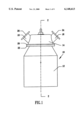
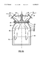
- FIG. 1 is an elevational view of a preferred embodiment of the present invention
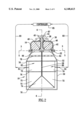
- FIG. 2 is a sectional view taken along the line 2--2 of FIG. 1, showing an internal structure of the valve and the catalytic converter;
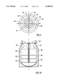
- FIG. 1 is a bottom plan view of a valve housing taken along line 3--3 of FIG. 2 with the valve disk removed, showing a position of a transverse wall which separates an interior cavity of the valve housing;
- FIG. 4 is a plan view of the valve disk, showing the two openings therein;
- FIG. 5 is a plan view of the container of the catalytic converter taken along the line 5--5 of FIG. 2, showing the position of the transverse plate which separates the interior of the container;
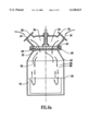
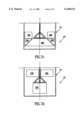
- FIG. 6a is a cross-sectional view taken along line 6--6 of FIG. 2, showing a direction of gas flow when the valve disk is in a first position;
- FIG. 6b is the same view as FIG. 6a, showing a direction of gas flow when the valve disk is in a second position in which the direction of gas flow is reversed;
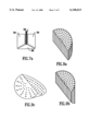
- FIG. 7a to FIG. 7d are diagrams showing different arrangements for monoliths in various embodiments of the invention, FIG. 7a appears on sheet 9 and FIG. 7b appears on sheet 4 of the drawings;
- FIG. 8 is a schematic side view of another embodiment of the invention.
- FIG. 9a to FIG. 9c are perspective views of monoliths used in the preferred embodiment but with graduated densities.
- the present invention relates to a reversing flow catalytic converter for treating exhaust gases from internal combustion engines.
- a catalytic converter 10 in accordance with the invention, comprises a container 12 and valve housing 14 which includes an exhaust gas inlet 16 and an exhaust gas outlet 18.
- the valve housing 14 has a flange 20 at its bottom end and is mounted to an adapter 22 at the top of the container 12 which will be described below in more detail.
- the exhaust gas inlet 16 has a flange 24 for the connection of an exhaust gas pipe and the exhaust gas outlet 18 has a similar flange 26 for the connection of a tail pipe. Therefore, exhaust gases that flow through the exhaust gas inlet 16 into the catalytic converter 10 are treated by a catalyst and then discharged to the tail pipe through the exhaust gas outlet 18.
- the angle of orientation of the exhaust gas inlet 16 and the exhaust gas outlet 18 are exemplary only. They may be oriented at other angles and the angles may not be the same.
- the valve housing 14 is circular in plan view and includes an interior cavity with an opening 28 at the bottom end (FIG. 3).
- a transverse wall 30 divides the interior cavity into two separate sections to form an intake cavity 32 that communicates with the exhaust gas inlet 16 and an exhaust cavity 34 that communicates with the exhaust gas outlet 18.
- the transverse wall 30 includes two identical halves located on opposite sides of a retainer sleeve 38 which extends from a bore 36 in the top of the valve housing 14 through the transverse wall 30 (see FIG. 2).
- the transverse wall 30 may be affixed to the valve housing 14, but preferably, the valve housing 14 including the flange 20, the transverse wall 30 and the retainer sleeve 38 are cast as an integral unit.
- Two locator bores 39 are provided in the flange 20. One of the bores 39 is located on a line which superposes the transverse wall 30 and the other is preferably offset about 5° from the line.
- the retainer sleeve 38 has an opening extending therethrough with an entrance at the distant end from the top of the valve housing 14. The entrance has a diameter larger than the opening and defines an inner shoulder 40 within the sleeve member 38 the function of which is explained below.
- a disk plate 42 is rotatably mounted to the bottom end of the valve housing 14.
- the valve disk 42 has a reciprocal rotary motion about a central axis which is perpendicular to the valve disk 42.
- a drive shaft 44 is fixed at one end to a centre of the valve disk 42 and extends rotatably through the retainer sleeve 38.
- a top end of the drive shaft 44 extends from the bore 36 and is rotatably supported by the bore 36.
- a bracket 45 is mounted to the top of the valve housing 14 to support a rotary actuator (not shown).
- the drive shaft 44 has an annular step 46 which is received in the enlarged diameter of the retainer sleeve 38 and axially restrained by the inner shoulder 40 of the retainer sleeve 38.
- the valve disk 42 includes two openings 48. Each opening 48 is slightly smaller than a one quarter section of the valve disk 42.
- the openings 48 are oriented 180° from each other so that each of the openings 48 communicates with only one of the intake cavity 32 and the exhaust cavity 34 when the valve disk 42 is either in a first position or in a second position. However, when the valve disk 42 is rotated from the first position to the second position, the openings 48 are moved to an opposite side of the transverse wall 30 and thereafter the openings 48 respectively communicate with the other of the intake cavity 32 and exhaust cavity 34.
- the valve disk 42 may be fixed to the end of the drive shaft 44 by any appropriate fastening mechanism, such as a screw or a bolt.
- a sidewall of the container 12 for the catalyst includes a cylindrical portion 50 and a frusto-conical portion 52.
- the adapter 22 includes a flat ring 54 (FIG. 5) and a diametrical beam 56 connected to the flat ring 54.
- the beam 56 has a circular central region 57.
- the adapter 22 is affixed to the top of the frusto-conical portion 52 of the sidewall and supports a transverse plate 58 (FIG. 2) which is affixed to a bottom side of the beam 56 and extends into an interior of the container 12.
- the transverse plate 58 separates the interior of the container 12 into a first section 60 and a second section 62 that communicate with each other at a bottom end of the container 12 to form a U-shaped exhaust gas passage.
- the first and second sections 60, 62 respectively communicate with a first port 64 and a second port 66 that are defined by a circular inner surface of the flat ring 54 and the beam 56.
- a pair of locator bores 68 are provided in the flat ring 54.
- One of the bores 68 is located on a diametrical line that is perpendicular to the beam 56 and the other is preferably offset by about 5° from the diametrical line.
- the two pairs of locator bores 39 and 68, together with a pair of locator pins (not illustrated) which are received in the respective bores, ensure that the transverse wall 30 is positioned at right angles to the beam 56 and the transverse wall 58 so that when the openings 48 are either in the first or the second position, each of the openings 48 communicates with only one of the sections 60, 62 of the container 12 and one of the intake cavity 32 and exhaust cavity 34.
- valve disk 42 As the valve disk 42 is rotated from the first to the second position, the openings 48 in the valve disk 42 are moved from one to the other of the intake cavity 32 and the exhaust cavity 34 but keep the same communication with one of the first and second ports 64, 66 respectively to achieve the reversal of gas flow. It should be understood that unidirectional rotation of the valve disk 42 can be used to achieve the same results.
- a pair of monolith sections 70 and 72 as well as a single monolith section 74 substantially fill the container as shown in FIG. 2.
- the shapes of the individual sections of monolith are illustrated in a perspective view in FIGS. 9a to 9c.
- the sections of monolith illustrated in FIGS. 9a to 9c have a graduated cell density, which is yet another feature of the invention.
- Each section of the monolith 70 is preferably a semi-cylindrical ceramic/metallic extrusion having cells axially extending therethrough.
- the cell density is preferably 100 cpsi, but the cell density is a matter of design choice.
- Each section of the monolith 72 is a semi-cylindrical ceramic extrusion having a bottom end that is cut at an angle of about 45°.
- the monolith 72 also has cells axially extending therethrough.
- the cell density of the monolith section 72 is preferably 200 cpsi.
- the monolith section 74 is a ceramic/metallic extrusion which is triangular in front view and may be substantially semicircular in side view.
- the monolith section 74 preferably has a cell density of 300 cpsi and the cells extend in a direction parallel to a bottom thereof.
- the monoliths are respectively coated with catalytic material and arranged in the container 12 in series in the flow passage which is defined by the inner surface of the container 12 and the transverse plate 58.
- the monolith section 74 is positioned at the bottom of the container 12 just beneath the transverse plate 58.
- Each section of the monolith 72 is located in one of the first and second sections 60 and 62 above the monolith section 74.
- Each section of the monolith 70 is located in one of the first and second sections 60 and 62, above the monolith section 72.
- the cells of adjacent pieces of monoliths communicate with each other so that the exhaust gases flowing through the gas flow passage within the container in either direction are drawn through the cells of each monolith section and contact the catalytic material coated on the monoliths.
- a layer of insulating material 75 such as vermiculite insulation fills a space between the monoliths and the inner surface of the container 12, as well as surrounding the bottom bowl 97.
- a monolith support 76, such as metal ring or the like, is provided between each section of the monolith to support it.
- a buffer plate 78 is located in the frusto-conical portion 52 of the container 12.
- the buffer plate 78 includes two semi-circular halves located on opposite sides of the transverse plate 58.
- a plurality of openings 80 in the buffer plate 78 (better illustrated in FIG. 5) permit exhaust gases to pass therethrough.
- the openings 80 distribute the gas flow evenly across the monolith sections 70.
- the buffer plate 58 also functions as a muffler to reduce engine noise.
- the catalytic converter 10 may completely replace a conventional muffler if enough buffer plates having an appropriate configuration are added to a top of the container 12.
- Two temperature sensors 81 are located in an upper region of the first and second sections 60, 62 of the container 12 (as shown in FIG. 2).
- the sensors 81 measure the temperature in each of the sections 60, 62 and send signal 83 to a computerised controller 85 which executes a control algorithm using the temperatures sensed by the sensors 81 as inputs to determine an optimal switching rate and position for the valve disk 42.
- the computerised controller operates the rotary actuator 87 mounted to the projecting end of the drive shaft 44 to move the rotating plate 42 from the first to the second position.
- the rotary actuator may be, for example, a pneumatic or electronic actuator that is commercially available.
- the frusto-conical portion 52 is connected to the cylindrical portion 50 after the inner components of the catalytic converter 10 are assembled.
- the frusto-conical portion 52 may be welded to the cylindrical portion 50 of the container 12.
- a desirable option is to use an annular V-clamp (not illustrated) to lock together skirted peripheral edges of both frusto-conical and the cylindrical portions in a manner well known in the art.
- FIGS. 6a and 6b a gas flow is periodically reversed as it enters the container 12 of the catalytic converter.
- An axial size of the valve disk 42 is enlarged in both FIGS. 6a and 6b to clearly show the openings 48 therein.
- one of the openings 48 in the valve disk 42 is at a left rear side of the exhaust cavity 34 and communicates with the second section 62 which is behind the transverse plate 58.
- the other one of the openings 48 in the plate 42 is at the right front side of the intake cavity 32 and communicates with the first section 60 which is in the front of the transverse plate 58.
- FIG. 6a show that the exhaust gases from the engine are introduced in the exhaust gas inlet 16 and enter the intake cavity 32, pass through the other one of the openings 48 at the right front (not shown), downwardly into the first section 60 of the container 12, passing through the catalytic monoliths (not shown) therein.
- the exhaust gases reach the bottom of the container 12, they enter the second section 62 of the container.
- the broken arrows in FIG. 6a show that the exhaust gases that entered the second section 62 of the container 12 flow upwardly and through the one of the openings 48 which is at the left rear and enter the exhaust cavity 34. The exhaust gases are then discharged to a tail pipe via the exhaust gas outlet 18.
- the openings 48 in the valve disk 42 are rotated 90° from their location in the first position.
- the opening 48 in the intake cavity 32 is at the right rear and communicates with the second section 62 which is behind the transverse plate 58.
- the other of the openings 48 in the valve disk 42 is on the left front of the transverse plate 58.
- the exhaust cavity 34 communicates with the first section 60, which is at the front of the transverse plate 58.
- the broken arrows in FIG. 6b show that the exhaust gases having entered the intake cavity 32 flow through one of the openings 48 at the right rear and downwardly into the second section 62 of the container 12, passing through the catalytic monoliths (not shown), reaching the bottom of the container 12 and entering the first section 60.
- the solid arrows in FIG. 6b show that the exhaust gases in the first section 60 flow upwardly and through the other one of the openings 48 which is at left front and enter the exhaust cavity 34.
- the exhaust gases are then discharged to a tail pipe via the exhaust gas outlet 18.
- the exhaust gases pass through the monoliths 70, 72 and 74 in alternating directions, contacting the catalytic material.
- the monolith 70 has, for example, a lower cell density of 100 cpsi, its heat capacity is therefore higher and the monolith is better protected from thermal stress.
- a monolith with low cell density and high heat capacity is able to withstand exposure to high temperature exhaust gases in the upstream of the exhaust gas flow.
- the exhaust gases flow into monoliths 72 and 74 which have higher cell density, they are exposed to more catalyst and the conversion performance is therefore more efficient.
- the exhaust gases flow through in the monoliths 70, 72 and 74 in both of the first and second sections 60, 62 and reach the top of the container 12, a large proportion of the noxious substances in the exhaust gases are converted into innocuous substances.
- FIG. 7a shows an alternate arrangement of the monolith series that includes two monolith sections 84 having a cell density of 100 cpsi and one monolith section 86 having a cell density of 300 cpsi.
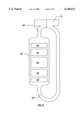
- FIG. 7b is a schematic diagram which shows another arrangement of the monolith series that includes 3 pairs of monoliths.
- monolith 88 has cell density of 100 cpsi.
- Monolith 90 has a cell density of 200 cpsi and monolith 92 has a cell density of 300 cpsi.
- the cell densities of the monoliths 88, 90 and 92 may be in other combinations such as 200, 300, 400, or 200, 300, 300.
- two venturis 94 and 96 are provided to achieve the same function.
- a spherically shaped bottom bowl 97 is provided to direct the gas flow smoothly from the first section to the second section and vice versa.
- FIG. 7c and FIG. 7d are schematic diagrams of two more potential arrangements for monoliths.
- the arrangement in FIG. 7c may be applied in a large catalytic converter. Instead of using large monolith sections, monoliths 100 are divided into small sections. Monoliths in small sections are usually more readily available through normal commercial channels.
- the monoliths 102 used in FIG. 7d are simpler in shape than the monoliths 72 and 74 used in the preferred embodiment of the invention.
- FIG. 8 is a schematic diagram of a converter 104 with monoliths 110, having its first and second ports 106 and 108 at opposite ends, which is an arrangement similar to conventional converter containers. This diagram illustrates how to use the adapter 22 to mount the valve unit of the present invention onto a converter container having the ports at opposite ends.
- FIGS. 9a to 9c show monoliths shaped like those used in the preferred embodiment of this invention, but with a unique cell structure.
- Each monolith has a radially graduated cell density which decreases from 400 cpsi in a region near a center of the container to 100 cpsi in a region near an outside wall of the container.
- the gas flow passages adjacent to the transverse plate 58 are shorter than the passages adjacent to the wall of the container 12.
- the monolith shown in FIGS. 9a-c promotes better conversion of the exhaust gases because the shorter passageway has a higher cell density and the catalytic conversion performance is therefore more balanced.
- An adsorbent material may also be deposited on the monoliths. The adsorbent material adsorbs pollutants during an engine start-up period before the catalyst ignites and release them as temperature rises.
Landscapes
- Engineering & Computer Science (AREA)
- Chemical & Material Sciences (AREA)
- Chemical Kinetics & Catalysis (AREA)
- Combustion & Propulsion (AREA)
- Mechanical Engineering (AREA)
- General Engineering & Computer Science (AREA)
- Health & Medical Sciences (AREA)
- Toxicology (AREA)
- Exhaust Gas After Treatment (AREA)
- Sliding Valves (AREA)
Priority Applications (5)
| Application Number | Priority Date | Filing Date | Title |
|---|---|---|---|
| US09/404,019 US6148613A (en) | 1998-10-21 | 1999-09-23 | Reversing flow catalytic converter for internal combustion engine |
| EP19990308230 EP0995887B1 (de) | 1998-10-21 | 1999-10-19 | Ventil zum umkehren der Strömungsrichtung in einem katalytischen Konverter einerBrennkraftmaschine |
| AT99308230T ATE221614T1 (de) | 1998-10-21 | 1999-10-19 | Ventil zum umkehren der strömungsrichtung in einem katalytischen konverter einerbrennkraftmaschine |
| DE69902334T DE69902334T2 (de) | 1998-10-21 | 1999-10-19 | Ventil zum umkehren der Strömungsrichtung in einem katalytischen Konverter einerBrennkraftmaschine |
| JP29875599A JP4477718B2 (ja) | 1998-10-21 | 1999-10-20 | 内燃機関用可逆流触媒コンバータ |
Applications Claiming Priority (2)
| Application Number | Priority Date | Filing Date | Title |
|---|---|---|---|
| US17635498A | 1998-10-21 | 1998-10-21 | |
| US09/404,019 US6148613A (en) | 1998-10-21 | 1999-09-23 | Reversing flow catalytic converter for internal combustion engine |
Related Parent Applications (1)
| Application Number | Title | Priority Date | Filing Date |
|---|---|---|---|
| US17635498A Continuation | 1998-10-21 | 1998-10-21 |
Publications (1)
| Publication Number | Publication Date |
|---|---|
| US6148613A true US6148613A (en) | 2000-11-21 |
Family
ID=26872137
Family Applications (1)
| Application Number | Title | Priority Date | Filing Date |
|---|---|---|---|
| US09/404,019 Expired - Fee Related US6148613A (en) | 1998-10-21 | 1999-09-23 | Reversing flow catalytic converter for internal combustion engine |
Country Status (5)
| Country | Link |
|---|---|
| US (1) | US6148613A (de) |
| EP (1) | EP0995887B1 (de) |
| JP (1) | JP4477718B2 (de) |
| AT (1) | ATE221614T1 (de) |
| DE (1) | DE69902334T2 (de) |
Cited By (14)
| Publication number | Priority date | Publication date | Assignee | Title |
|---|---|---|---|---|
| US6588203B2 (en) * | 2000-07-03 | 2003-07-08 | Toyota Jidosha Kabushiki Kaisha | Exhaust device of internal combustion engine |
| US20050081930A1 (en) * | 2003-10-15 | 2005-04-21 | Margiott Paul R. | Single valve fuel cell stack gas flow and containment |
| US20050210865A1 (en) * | 2004-03-24 | 2005-09-29 | Bolander Thomas E | Accelerating catalytic conversion |
| US20060266025A1 (en) * | 2005-05-24 | 2006-11-30 | Ecocing Corporation | Reversing flow catalytic converter for internal combustion engines |
| US20080178585A1 (en) * | 2007-01-31 | 2008-07-31 | Philip Stephen Bruza | Exhaust treatment device having flow-promoting end caps |
| US20100269494A1 (en) * | 2008-07-10 | 2010-10-28 | Hitachi Construction Machinery Co., Ltd. | Exhaust gas treatment apparatus |
| US20100269488A1 (en) * | 2003-08-01 | 2010-10-28 | Bailey John M | Particulate trap system and method |
| US20120247086A1 (en) * | 2011-03-30 | 2012-10-04 | GM Global Technology Operations LLC | Exhaust methane control systems and methods |
| US20140174057A1 (en) * | 2012-12-26 | 2014-06-26 | Caterpillar Inc. | Exhaust Gas Aftertreatment Module |
| US20150047323A1 (en) * | 2013-08-16 | 2015-02-19 | Ford Global Technologies, Llc | Multi-cell structure for automotive catalyst support |
| WO2015189457A1 (en) | 2014-06-09 | 2015-12-17 | Wärtsilä Finland Oy | Bypass device of an exhaust system of a turbocharged internal combustion engine and a system comprising a bypass device |
| US20160131014A1 (en) * | 2014-11-10 | 2016-05-12 | Ge Jenbacher Gmbh & Co Og | Catalytic converter device for a stationary internal combustion engine |
| DE102016123925A1 (de) * | 2016-12-09 | 2018-06-14 | Avl Emission Test Systems Gmbh | Analyseeinheit |
| US10960337B2 (en) * | 2016-10-18 | 2021-03-30 | Hug Engineering Ag | Soot particle filter and method for operating a soot particle filter |
Families Citing this family (3)
| Publication number | Priority date | Publication date | Assignee | Title |
|---|---|---|---|---|
| JP4680103B2 (ja) * | 2006-03-16 | 2011-05-11 | 三菱ふそうトラック・バス株式会社 | 内燃機関の排気浄化装置 |
| WO2013175056A1 (en) * | 2012-05-22 | 2013-11-28 | Wärtsilä Finland Oy | Method and arrangement for preventing clogging of exhaust system components |
| DE102012020420B4 (de) | 2012-10-18 | 2021-04-29 | Volkswagen Aktiengesellschaft | Verzweigungs- oder Zusammenführungselement für gasförmige Fluide |
Citations (13)
| Publication number | Priority date | Publication date | Assignee | Title |
|---|---|---|---|---|
| US3172251A (en) * | 1963-01-14 | 1965-03-09 | Minnesota Mining & Mfg | Afterburner system |
| US3189417A (en) * | 1962-05-29 | 1965-06-15 | Oxy Catalyst Inc | Apparatus for improving the purification of exhaust gases from an internal combustion engine |
| US3607133A (en) * | 1968-10-23 | 1971-09-21 | Kachita Co Ltd | Apparatus for removing carbon monoxide from room air and exhaust gas |
| US3962869A (en) * | 1972-09-04 | 1976-06-15 | Robert Bosch G.M.B.H. | Equipment for exhaust gas detoxification in internal combustion engines |
| US4047895A (en) * | 1975-10-30 | 1977-09-13 | Uop Inc. | Apparatus for the purification of engine exhaust gases without oxidation of entrained SO2 |
| US4139355A (en) * | 1977-04-28 | 1979-02-13 | Essex Group, Inc. | Four wave valve for reversible cycle refrigeration system |
| US4969328A (en) * | 1986-10-21 | 1990-11-13 | Kammel Refaat A | Diesel engine exhaust oxidizer |
| GB2246715A (en) * | 1990-08-11 | 1992-02-12 | Ford Motor Co | Reducing light-off time in a catalytic converter |
| WO1995023917A1 (en) * | 1994-03-04 | 1995-09-08 | Salem Engelhard | Two chamber regenerative oxidizer with valve control |
| US5585005A (en) * | 1989-12-06 | 1996-12-17 | University Of Toronto Innovations Foundation | Method for effecting gas-liquid contact |
| WO1997003277A1 (de) * | 1995-07-12 | 1997-01-30 | Firma Carl Freudenberg | Vorrichtung zur reinigung von abgas einer gemischverdichtenden verbrennungskraftmaschine |
| US5701735A (en) * | 1994-08-08 | 1997-12-30 | Toyota Jidosha Kabushiki Kaisha | Method for regenerating a particulate collection filter and an exhaust emission control system with a particulate collection filter |
| WO1998020238A1 (en) * | 1996-11-08 | 1998-05-14 | Matros Technologies, Inc. | Emission control system |
Family Cites Families (3)
| Publication number | Priority date | Publication date | Assignee | Title |
|---|---|---|---|---|
| JPS54134071A (en) * | 1978-04-10 | 1979-10-18 | Daikin Ind Ltd | Catalytic oxidizer |
| JPH04326924A (ja) * | 1991-04-25 | 1992-11-16 | Matsushita Electric Ind Co Ltd | 間欠式触媒浄化装置および浄化方法 |
| JP3801335B2 (ja) * | 1997-12-16 | 2006-07-26 | 三菱ふそうトラック・バス株式会社 | 排気浄化装置 |
-
1999
- 1999-09-23 US US09/404,019 patent/US6148613A/en not_active Expired - Fee Related
- 1999-10-19 DE DE69902334T patent/DE69902334T2/de not_active Expired - Fee Related
- 1999-10-19 AT AT99308230T patent/ATE221614T1/de not_active IP Right Cessation
- 1999-10-19 EP EP19990308230 patent/EP0995887B1/de not_active Expired - Lifetime
- 1999-10-20 JP JP29875599A patent/JP4477718B2/ja not_active Expired - Lifetime
Patent Citations (14)
| Publication number | Priority date | Publication date | Assignee | Title |
|---|---|---|---|---|
| US3189417A (en) * | 1962-05-29 | 1965-06-15 | Oxy Catalyst Inc | Apparatus for improving the purification of exhaust gases from an internal combustion engine |
| US3172251A (en) * | 1963-01-14 | 1965-03-09 | Minnesota Mining & Mfg | Afterburner system |
| US3607133A (en) * | 1968-10-23 | 1971-09-21 | Kachita Co Ltd | Apparatus for removing carbon monoxide from room air and exhaust gas |
| US3962869A (en) * | 1972-09-04 | 1976-06-15 | Robert Bosch G.M.B.H. | Equipment for exhaust gas detoxification in internal combustion engines |
| US4047895A (en) * | 1975-10-30 | 1977-09-13 | Uop Inc. | Apparatus for the purification of engine exhaust gases without oxidation of entrained SO2 |
| US4139355A (en) * | 1977-04-28 | 1979-02-13 | Essex Group, Inc. | Four wave valve for reversible cycle refrigeration system |
| US4969328A (en) * | 1986-10-21 | 1990-11-13 | Kammel Refaat A | Diesel engine exhaust oxidizer |
| US5585005A (en) * | 1989-12-06 | 1996-12-17 | University Of Toronto Innovations Foundation | Method for effecting gas-liquid contact |
| GB2246715A (en) * | 1990-08-11 | 1992-02-12 | Ford Motor Co | Reducing light-off time in a catalytic converter |
| WO1995023917A1 (en) * | 1994-03-04 | 1995-09-08 | Salem Engelhard | Two chamber regenerative oxidizer with valve control |
| US5701735A (en) * | 1994-08-08 | 1997-12-30 | Toyota Jidosha Kabushiki Kaisha | Method for regenerating a particulate collection filter and an exhaust emission control system with a particulate collection filter |
| WO1997003277A1 (de) * | 1995-07-12 | 1997-01-30 | Firma Carl Freudenberg | Vorrichtung zur reinigung von abgas einer gemischverdichtenden verbrennungskraftmaschine |
| WO1998020238A1 (en) * | 1996-11-08 | 1998-05-14 | Matros Technologies, Inc. | Emission control system |
| US5768888A (en) * | 1996-11-08 | 1998-06-23 | Matros Technologies, Inc. | Emission control system |
Non-Patent Citations (6)
| Title |
|---|
| RFC, "Gasoline Direct Injection and Diesel Aftertreatment", SAE SSP-1470, pp. 103-109, Dec. 1999. |
| RFC, Gasoline Direct Injection and Diesel Aftertreatment , SAE SSP 1470, pp. 103 109, Dec. 1999. * |
| Stuart R. Bell Emissions, "Fuels and Lubricants and HSDI Engine", ICE-vol. 33-1, p. 102, Oct. 1999. |
| Stuart R. Bell Emissions, Fuels and Lubricants and HSDI Engine , ICE vol. 33 1, p. 102, Oct. 1999. * |
| Zeng et al., A Novel Reverse Flow Catalytic Converter Operated on an Isuzu 6HH1 Diesel Dual Fuel Engine, p. 101, Dec. 1999. * |
| Zeng et al., A Novel Reverse-Flow Catalytic Converter Operated on an Isuzu-6HH1 Diesel Dual Fuel Engine, p. 101, Dec. 1999. |
Cited By (35)
| Publication number | Priority date | Publication date | Assignee | Title |
|---|---|---|---|---|
| US6588203B2 (en) * | 2000-07-03 | 2003-07-08 | Toyota Jidosha Kabushiki Kaisha | Exhaust device of internal combustion engine |
| US7992382B2 (en) * | 2003-08-01 | 2011-08-09 | Illinois Valley Holding Company | Particulate trap system and method |
| US20100269488A1 (en) * | 2003-08-01 | 2010-10-28 | Bailey John M | Particulate trap system and method |
| US20050081930A1 (en) * | 2003-10-15 | 2005-04-21 | Margiott Paul R. | Single valve fuel cell stack gas flow and containment |
| US6959730B2 (en) * | 2003-10-15 | 2005-11-01 | Utc Fuel Cells, Llc | Single valve fuel cell stack gas flow and containment |
| US7210287B2 (en) * | 2004-03-24 | 2007-05-01 | General Motors Corporation | Accelerating catalytic conversion |
| US20050210865A1 (en) * | 2004-03-24 | 2005-09-29 | Bolander Thomas E | Accelerating catalytic conversion |
| US7398645B2 (en) * | 2005-05-24 | 2008-07-15 | Smart Muffler Corporation | Reversing flow catalytic converter for internal combustion engines |
| EP1896702A4 (de) * | 2005-05-24 | 2009-04-29 | Smart Muffler Corp | Verbesserter stromumkehrkatalysator für brennkraftmaschinen |
| US20060283173A1 (en) * | 2005-05-24 | 2006-12-21 | Ming Zheng | Further improved reversing flow catalytic converter for internal combustion engines |
| WO2006125311A1 (en) * | 2005-05-24 | 2006-11-30 | Smart Muffler Corporation | Improved reversing flow catalytic converter for internal combustion engines |
| US20060266025A1 (en) * | 2005-05-24 | 2006-11-30 | Ecocing Corporation | Reversing flow catalytic converter for internal combustion engines |
| US20080178585A1 (en) * | 2007-01-31 | 2008-07-31 | Philip Stephen Bruza | Exhaust treatment device having flow-promoting end caps |
| US7757484B2 (en) * | 2007-01-31 | 2010-07-20 | Caterpillar Inc. | Exhaust treatment device having flow-promoting end caps |
| US20100263353A1 (en) * | 2007-01-31 | 2010-10-21 | Philip Stephen Bruza | Exhaust treatment device having flow-promoting end caps |
| US8359848B2 (en) | 2007-01-31 | 2013-01-29 | Caterpillar Inc. | Exhaust treatment device having flow-promoting end caps |
| US8420019B2 (en) | 2008-07-10 | 2013-04-16 | Hitachi Construction Machinery Co., Ltd. | Exhaust gas treatment apparatus |
| US20100269494A1 (en) * | 2008-07-10 | 2010-10-28 | Hitachi Construction Machinery Co., Ltd. | Exhaust gas treatment apparatus |
| US20120247086A1 (en) * | 2011-03-30 | 2012-10-04 | GM Global Technology Operations LLC | Exhaust methane control systems and methods |
| US8839605B2 (en) * | 2011-03-30 | 2014-09-23 | GM Global Technology Operations LLC | Exhaust methane control systems and methods |
| US20140174057A1 (en) * | 2012-12-26 | 2014-06-26 | Caterpillar Inc. | Exhaust Gas Aftertreatment Module |
| US9556781B2 (en) * | 2012-12-26 | 2017-01-31 | Caterpillar Inc. | Exhaust gas aftertreatment module |
| US8978369B2 (en) * | 2012-12-26 | 2015-03-17 | Caterpillar Inc. | Exhaust gas aftertreatment module |
| US20150159537A1 (en) * | 2012-12-26 | 2015-06-11 | Caterpillar Inc. | Exhaust Gas Aftertreatment Module |
| US9512766B2 (en) * | 2013-08-16 | 2016-12-06 | Ford Global Technologies, Llc | Multi-cell structure for automotive catalyst support |
| US20150047323A1 (en) * | 2013-08-16 | 2015-02-19 | Ford Global Technologies, Llc | Multi-cell structure for automotive catalyst support |
| WO2015189457A1 (en) | 2014-06-09 | 2015-12-17 | Wärtsilä Finland Oy | Bypass device of an exhaust system of a turbocharged internal combustion engine and a system comprising a bypass device |
| US20160131014A1 (en) * | 2014-11-10 | 2016-05-12 | Ge Jenbacher Gmbh & Co Og | Catalytic converter device for a stationary internal combustion engine |
| CN105756759A (zh) * | 2014-11-10 | 2016-07-13 | Ge延巴赫两合无限公司 | 用于固定式内燃机的催化装置和包括催化装置的配置系统 |
| US9816427B2 (en) * | 2014-11-10 | 2017-11-14 | Ge Jenbacher Gmbh & Co Og | Catalytic converter device for a stationary internal combustion engine |
| CN105756759B (zh) * | 2014-11-10 | 2019-11-05 | Ge延巴赫两合无限公司 | 用于固定式内燃机的催化装置和包括催化装置的配置系统 |
| US10960337B2 (en) * | 2016-10-18 | 2021-03-30 | Hug Engineering Ag | Soot particle filter and method for operating a soot particle filter |
| DE102016123925A1 (de) * | 2016-12-09 | 2018-06-14 | Avl Emission Test Systems Gmbh | Analyseeinheit |
| DE102016123925B4 (de) * | 2016-12-09 | 2019-03-28 | Avl Emission Test Systems Gmbh | Winkelflansch für eine Analyseeinheit |
| US10935530B2 (en) | 2016-12-09 | 2021-03-02 | Avl Emission Test Systems Gmbh | Analysis unit for removable installation of a gas measurement device |
Also Published As
| Publication number | Publication date |
|---|---|
| ATE221614T1 (de) | 2002-08-15 |
| EP0995887A2 (de) | 2000-04-26 |
| EP0995887A3 (de) | 2000-05-24 |
| DE69902334T2 (de) | 2003-03-27 |
| JP2000130156A (ja) | 2000-05-09 |
| EP0995887B1 (de) | 2002-07-31 |
| JP4477718B2 (ja) | 2010-06-09 |
| DE69902334D1 (de) | 2002-09-05 |
Similar Documents
| Publication | Publication Date | Title |
|---|---|---|
| US6148613A (en) | Reversing flow catalytic converter for internal combustion engine | |
| US5768888A (en) | Emission control system | |
| CA2291900C (en) | Emission control apparatus and method of internal combustion engine | |
| KR100590960B1 (ko) | 자동차 배기가스 정화시스템 | |
| JP3526084B2 (ja) | 排ガス浄化用吸着・触媒体、吸着体、排ガス浄化システム及び排ガス浄化方法 | |
| JP3951422B2 (ja) | 多気筒内燃機関の排気浄化装置 | |
| EP0875666B1 (de) | Vorrichtung zur Abgasreinigung für eine Brennkraftmaschine | |
| US5771684A (en) | Gas treatment systems | |
| EP1583890B1 (de) | Nox-reduzierende durchflussadsorptionseinheit für verbrennungsmotoren | |
| US5787707A (en) | In-line adsorber system | |
| US5410876A (en) | Catalytic converter assembly with bypass | |
| US7398645B2 (en) | Reversing flow catalytic converter for internal combustion engines | |
| CA2251393C (en) | Reversing flow catalytic converter for internal combustion engine | |
| US5634333A (en) | Exhaust pipe opening and closing apparatus | |
| JPH0754640A (ja) | 排気浄化装置 | |
| ES2451643T3 (es) | Sistema de escape de motor de combustión interna | |
| RU2075607C1 (ru) | Каталитический нейтрализатор отработавших газов | |
| JPH09264125A (ja) | 排気バイパスシステム | |
| JP3585724B2 (ja) | 内燃機関の排ガス浄化装置 | |
| RU2138653C1 (ru) | Каталитический нейтрализатор отработавших газов карбюраторного двигателя | |
| JP2003239730A (ja) | エンジンの排気ガス浄化装置 | |
| JPH0711940A (ja) | エンジンの排気ガス浄化装置 | |
| US20050092688A1 (en) | System and process for treating contaminated fluid system | |
| JP2005207270A (ja) | エンジンの排気ガス浄化装置 | |
| JPH04255520A (ja) | 内燃機関における炭化水素系ガス成分吸着システム |
Legal Events
| Date | Code | Title | Description |
|---|---|---|---|
| AS | Assignment |
Owner name: ALTERNATIVE FUEL SYSTEMS, INC., CANADA Free format text: ASSIGNMENT OF ASSIGNORS INTEREST;ASSIGNORS:KLOPP, GERHARD O.;MIROSH, EDWARD;ZHENG, MING;REEL/FRAME:010271/0634;SIGNING DATES FROM 19990823 TO 19990825 |
|
| FPAY | Fee payment |
Year of fee payment: 4 |
|
| AS | Assignment |
Owner name: ALTERNATIVE FUEL SYSTEMS (2004) INC., CANADA Free format text: ASSIGNMENT OF ASSIGNORS INTEREST;ASSIGNOR:ALTERNATIVE FUEL SYSTEMS INC.;REEL/FRAME:017164/0730 Effective date: 20051003 |
|
| FPAY | Fee payment |
Year of fee payment: 8 |
|
| REMI | Maintenance fee reminder mailed | ||
| LAPS | Lapse for failure to pay maintenance fees | ||
| STCH | Information on status: patent discontinuation |
Free format text: PATENT EXPIRED DUE TO NONPAYMENT OF MAINTENANCE FEES UNDER 37 CFR 1.362 |
|
| FP | Lapsed due to failure to pay maintenance fee |
Effective date: 20121121 |