US6149044A - Supporting mechanism for pinch roller unit for use in magnetic recording/reproducing apparatus - Google Patents
Supporting mechanism for pinch roller unit for use in magnetic recording/reproducing apparatus Download PDFInfo
- Publication number
- US6149044A US6149044A US09/128,972 US12897298A US6149044A US 6149044 A US6149044 A US 6149044A US 12897298 A US12897298 A US 12897298A US 6149044 A US6149044 A US 6149044A
- Authority
- US
- United States
- Prior art keywords
- shaft
- supporting
- magnetic tape
- hollow shaft
- roller
- Prior art date
- Legal status (The legal status is an assumption and is not a legal conclusion. Google has not performed a legal analysis and makes no representation as to the accuracy of the status listed.)
- Expired - Fee Related
Links
Images


Classifications
-
- G—PHYSICS
- G11—INFORMATION STORAGE
- G11B—INFORMATION STORAGE BASED ON RELATIVE MOVEMENT BETWEEN RECORD CARRIER AND TRANSDUCER
- G11B15/00—Driving, starting or stopping record carriers of filamentary or web form; Driving both such record carriers and heads; Guiding such record carriers or containers therefor; Control thereof; Control of operating function
- G11B15/18—Driving; Starting; Stopping; Arrangements for control or regulation thereof
- G11B15/26—Driving record carriers by members acting directly or indirectly thereon
- G11B15/28—Driving record carriers by members acting directly or indirectly thereon through rollers driving by frictional contact with the record carrier, e.g. capstan; Multiple arrangements of capstans or drums coupled to means for controlling the speed of the drive; Multiple capstan systems alternately engageable with record carrier to provide reversal
- G11B15/29—Driving record carriers by members acting directly or indirectly thereon through rollers driving by frictional contact with the record carrier, e.g. capstan; Multiple arrangements of capstans or drums coupled to means for controlling the speed of the drive; Multiple capstan systems alternately engageable with record carrier to provide reversal through pinch-rollers or tape rolls
Definitions
- the present invention relates to a supporting mechanism for use with a pinch roller unit which causes a magnetic tape, used in a magnetic recording/reproducing apparatus or the like, to be in pressure contact with a capstan shaft.
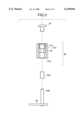
- FIG. 2 is a top view of a magnetic recording/reproducing apparatus.
- FIG. 6 is a cross-sectional view of a supporting mechanism for a conventional pinch roller unit.
- a cassette 60 houses the tape 6 therein with a magnetic tape 6 wound on reels.
- a guide roller 12 draws the magnetic tape 6 out of the cassette 60 and wraps the magnetic tape 6 round a rotating drum 10.
- the drum 10 is provided with magnetic heads which record the video signal and audio signal on the magnetic tap or reproduce the signals from the tape.
- a pinch roller unit 20 presses the magnetic tape 6 against the capstan shaft 16 so that the magnetic tape 6 travels at a constant speed.
- a tape guide mechanism 9 guides the travel of a magnetic tape 6.
- the magnetic tape 6 runs between the capstan shaft 16 and the pinch roller 20 and passes an A/C head (audio control head) 15 which reads the audio signal and control signals recorded on the magnetic tape 6.
- the magnetic tape 6 passes an erase head 13 and is further guided by a post pin 14 before being taken up into the cassette 60.
- the erase head 13 erases the signals recorded on the magnetic tape 6.
- the post pin 14 defines an angle at which the magnetic tape 6 is wrapped round a back tension mechanism 11.
- the back tension mechanism 11 controls a tension applied to the magnetic tape 6. All of the aforementioned structural elements are carried on a chassis 1.
- FIG. 6 shows one 20 of known pinch roller assembly 20 of the aforementioned type.
- the pinch roller assembly 20 includes a pinch roller 21, fixing shaft 25 on which the pinch roller 21 is rotatably mounted, and a pivot arm 26 that holds the fixing shaft 25 so that the fixing shaft vertically rises from pivotal arm 26.
- the pinch roller 21 includes a rubber roller 21a, core metal shaft 21b, ball bearing 22, and bushing 21c.
- the rubber roller 21a presses the magnetic tape 6 against the capstan shaft 16, thereby allowing the magnetic tape to travel at a constant speed.
- the core metal shaft 21b is a hollow cylinder and has a stepped portion. The rubber roller 21a fits over the core metal shaft 21b for secure engagement.
- the ball bearing 22 inserted into the core metal shaft 21b and abuts the stepped portion.
- the bushing 21c serves as a stopper that prevents pull-out of the ball bearing 22.
- a cap 23 is mounted on an upper portion of the support shaft 25b to restrict the movement of the pinch roller 21 in the thrust direction.
- the fixing shaft 25 is formed of, for example, stainless steel (SUS) in one-piece construction and includes a flange shaft 25a and a supporting shaft 25b.
- the flange shaft 25a supports the pinch roller 21 at a predetermined height with respect to the magnetic tape 6.
- the supporting shaft 25b supports the ball bearing 22 thereon.
- the one-piece construction of the flange shaft 25a and supporting shaft 25b has a disadvantage that fine adjustment of the marginal movement in the thrust direction and height of the pinch roller 21 cannot be made with respect to the magnetic tape 6.
- the shape of the boundary between the flange shaft 25a and support shaft 25b is complex and is difficult to be machined. Moreover, the support shaft 25b is difficult to machine for sufficient smoothness of its cylindrical surface.
- the present invention was made to solve the aforementioned drawbacks of the conventional pinch roller unit.
- An object of the invention is to provide a pinch roller unit where the fixing shaft includes two separate parts, i.e., a supporting shaft and a hollow shaft, so that the fine adjustment of the marginal movement in thrust direction and height can be simplified, the shapes are simple to machine, and surface accuracy can easily be achieved.
- a supporting mechanism of the invention is for supporting a pinch roller for use in a magnetic recording/reproducing apparatus.
- the pinch roller is held at a predetermined height with respect to a recording tape.
- the supporting mechanism includes a supporting shaft and a hollow shaft.
- the supporting shaft rotatably supports the pinch roller.
- the supporting shaft press-fittingly extends through the hollow shaft.
- the hollow shaft is adjustably secured to the supporting shaft and is positioned in an axial direction of the supporting shaft so that the height of the pinch roller is adjusted with respect to the recording tape.
- FIG. 1 is a cross-sectional view of a pinch roller unit according to an embodiment of the invention
- FIG. 2 is a top view of a magnetic recording/reproducing apparatus
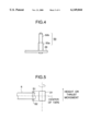
- FIG. 3 is a cross-sectional view of a supporting mechanism for a pinch roller assembly in accordance with the invention.
- FIG. 4 shows the hollow shaft 50a fitted over the supporting shaft 50b
- FIG. 5 shows the height of the pinch roller 21 with respect to the magnetic tape
- FIG. 6 is a cross-sectional view of a supporting mechanism for a conventional pinch roller unit.
- FIG. 1 is a cross-sectional view of a pinch roller unit according to the invention.
- the pinch roller unit 21 differs from the conventional pinch roller unit in that a fixing shaft 50 is of different construction.
- the pinch roller 21 includes a rubber roller 21a, a core metal shaft 21b, a ball bearing 22, and a stopper (bushing) 21c.
- the rubber roller 21a presses the magnetic tape 6 against the capstan shaft 16, thereby allowing the magnetic tape 6 to travel at a constant speed.
- the core metal shaft 21b is a hollow cylinder with a stepped portion formed in the inner surface thereof and has the rubber roller 21a securely fitted thereover.
- the ball bearing 22 is inserted into the core metal shaft 21b and abuts the stepped portion.
- the stopper 21c prevents pull-out of the ball bearing 22.
- the fixing shaft 50 includes a supporting shaft 50b and a hollow shaft 50a.
- the supporting shaft 50b is press-fitted into the hollow shaft 50a and the supporting shaft 50b receives the ball bearing 22 thereon.
- the hollow shaft 50a may be a hollow cylinder formed of a metal (e.g., copper) softer than a metal material of the supporting shaft 50b or may be a bushing molded from a thermal plastic material.
- the material of the hollow shaft 50a softer than the supporting shaft 50b facilitates the insertion of the supporting shaft 50b into the hollow shaft 50a.
- the supporting shaft 50b serves to hold the pinch roller 20 at a predetermined height with respect to the magnetic tape 6.
- the pivotal arm 26 holds the supporting shaft 50b so that the fixing shaft 50 vertically rises from pivotal arm 26.
- FIG. 3 is an exploded side view of the pinch roller unit 20 of the invention. The assembly operation of the fixing shaft 50 and pinch roller 21 of the aforementioned construction will be described with reference to FIG. 3.
- the supporting shaft 50b is first fixed by, for example, high spin caulking to the arm 26 such that the supporting shaft 50b rises vertically from the arm 26. Then, the hollow shaft 50a is press-fitted to the supporting shaft 50b as shown in FIG. 4, thereby completing the assembly of the fixing shaft 50.
- the supporting shaft 50b may be press-fitted by, for example, high spin caulking into the hollow shaft 50a before vertically fixing the supporting shaft 50b to the arm 26. Then, the pinch roller 21 is assembled onto the supporting shaft 50b of the fixing shaft 50. Finally, the cap 23 is fitted to the top portion of the supporting shaft 50b, thereby completing the pinch roller unit 20.
- the tape guide rollers 12 draw the magnetic tape 6 from the cassette 60 in which the magnetic tape 6 is wound on reels.
- the magnetic tape 6 is wrapped around the rotating drum 10.
- the magnetic tape 6 runs through the post pin 14, back tension mechanism 11, tape guide mechanism 9, erase head 13, and A/C head 15.
- the pinch roller 20 presses the magnetic tape 6 against the capstan shaft 16 so that the magnetic tape 6 is supplied from a supply reel, runs at a constant speed, and is finally taken up by a take-up reel, not shown.
- the pinch roller 20 includes the fixing shaft 50 of two-piece construction including the hollow shaft 50a and supporting shaft 50b.
- the two-piece construction facilitates fine adjustments of the height and marginal thrust movement of the pinch roller 21 relative to the magnetic tape 6.
- the adjustment can be carried out during the manufacture of the magnetic recording/reproducing apparatus, for example, when the traveling condition of tape is checked.
- the margin S1 and S2 are preferably substantially the same.
- the hollow shaft 50a and supporting shaft 50b are of simple cylindrical shapes. Such simple shapes of the hollow shaft 50a and supporting shaft 50b makes them easy to machine and lends itself to achieving a smooth cylindrical surface of the shafts 50a and 50b.
Landscapes
- Registering, Tensioning, Guiding Webs, And Rollers Therefor (AREA)
- Rolls And Other Rotary Bodies (AREA)
Applications Claiming Priority (2)
| Application Number | Priority Date | Filing Date | Title |
|---|---|---|---|
| JP9-211957 | 1997-08-06 | ||
| JP9211957A JPH1153787A (ja) | 1997-08-06 | 1997-08-06 | 磁気記録再生装置 |
Publications (1)
| Publication Number | Publication Date |
|---|---|
| US6149044A true US6149044A (en) | 2000-11-21 |
Family
ID=16614511
Family Applications (1)
| Application Number | Title | Priority Date | Filing Date |
|---|---|---|---|
| US09/128,972 Expired - Fee Related US6149044A (en) | 1997-08-06 | 1998-08-04 | Supporting mechanism for pinch roller unit for use in magnetic recording/reproducing apparatus |
Country Status (3)
| Country | Link |
|---|---|
| US (1) | US6149044A (fr) |
| EP (1) | EP0896330A3 (fr) |
| JP (1) | JPH1153787A (fr) |
Cited By (1)
| Publication number | Priority date | Publication date | Assignee | Title |
|---|---|---|---|---|
| US6648199B2 (en) * | 2001-02-15 | 2003-11-18 | Funai Electric Co., Ltd. | Pinch roller device |
Families Citing this family (1)
| Publication number | Priority date | Publication date | Assignee | Title |
|---|---|---|---|---|
| CN115893068B (zh) * | 2022-08-09 | 2023-11-10 | 安徽鼎宏橡塑科技股份有限公司 | 一种防止飞絮堵塞的纺织加工用传输辊 |
Citations (7)
| Publication number | Priority date | Publication date | Assignee | Title |
|---|---|---|---|---|
| US3402868A (en) * | 1966-12-16 | 1968-09-24 | Vm Corp | Tape drive arrangement |
| EP0423883A2 (fr) * | 1989-10-17 | 1991-04-24 | Koninklijke Philips Electronics N.V. | Appareil à bande et disposition à galet presseur pour cet appareil |
| EP0576083A2 (fr) * | 1992-06-26 | 1993-12-29 | Koninklijke Philips Electronics N.V. | Appareil à bande magnétique comprenant un dispositif à galet presseur |
| US5373982A (en) * | 1992-09-24 | 1994-12-20 | Takahashi; Shigeo | Automatically tiltable small roller structure of slide bearing type for video tape recorders |
| DE4320680C1 (de) * | 1993-06-22 | 1995-01-26 | Gmd Praezisionsgummifabrik Geo | Andruckrolle für Magnetbänder sowie Verfahren zu ihrer Herstellung |
| JPH08297888A (ja) * | 1995-04-20 | 1996-11-12 | Daewoo Electron Co Ltd | テープレコーダーのピンチローラ組立体 |
| US5626273A (en) * | 1994-02-18 | 1997-05-06 | U.S. Philips Corporation | Recording and/or reproducing apparatus with movable guide roller |
-
1997
- 1997-08-06 JP JP9211957A patent/JPH1153787A/ja active Pending
-
1998
- 1998-06-25 EP EP98305016A patent/EP0896330A3/fr not_active Withdrawn
- 1998-08-04 US US09/128,972 patent/US6149044A/en not_active Expired - Fee Related
Patent Citations (7)
| Publication number | Priority date | Publication date | Assignee | Title |
|---|---|---|---|---|
| US3402868A (en) * | 1966-12-16 | 1968-09-24 | Vm Corp | Tape drive arrangement |
| EP0423883A2 (fr) * | 1989-10-17 | 1991-04-24 | Koninklijke Philips Electronics N.V. | Appareil à bande et disposition à galet presseur pour cet appareil |
| EP0576083A2 (fr) * | 1992-06-26 | 1993-12-29 | Koninklijke Philips Electronics N.V. | Appareil à bande magnétique comprenant un dispositif à galet presseur |
| US5373982A (en) * | 1992-09-24 | 1994-12-20 | Takahashi; Shigeo | Automatically tiltable small roller structure of slide bearing type for video tape recorders |
| DE4320680C1 (de) * | 1993-06-22 | 1995-01-26 | Gmd Praezisionsgummifabrik Geo | Andruckrolle für Magnetbänder sowie Verfahren zu ihrer Herstellung |
| US5626273A (en) * | 1994-02-18 | 1997-05-06 | U.S. Philips Corporation | Recording and/or reproducing apparatus with movable guide roller |
| JPH08297888A (ja) * | 1995-04-20 | 1996-11-12 | Daewoo Electron Co Ltd | テープレコーダーのピンチローラ組立体 |
Cited By (1)
| Publication number | Priority date | Publication date | Assignee | Title |
|---|---|---|---|---|
| US6648199B2 (en) * | 2001-02-15 | 2003-11-18 | Funai Electric Co., Ltd. | Pinch roller device |
Also Published As
| Publication number | Publication date |
|---|---|
| EP0896330A2 (fr) | 1999-02-10 |
| EP0896330A3 (fr) | 1999-03-03 |
| JPH1153787A (ja) | 1999-02-26 |
Similar Documents
| Publication | Publication Date | Title |
|---|---|---|
| US4155497A (en) | Tape transport mechanism for recording/reproducing apparatus, particularly for video tape recording use | |
| KR930001876B1 (ko) | 비디오 레코더의 테이프 주행장치 | |
| US5307219A (en) | Tape loading device | |
| US6149044A (en) | Supporting mechanism for pinch roller unit for use in magnetic recording/reproducing apparatus | |
| GB2311586A (en) | Video cassette recorder pinch roller asembly | |
| US3957219A (en) | Endless tape traveling device | |
| US3863853A (en) | Endless magnetic tape cartridge | |
| US20030179504A1 (en) | Rotary head drum unit and magnetic tape drive | |
| JPS624927Y2 (fr) | ||
| KR0179247B1 (ko) | 비디오기기의 핀치롤러 장치 | |
| US5803335A (en) | Pinch roller assembly having a rubber cushion for making a contact surface thereof pivotable | |
| US5833125A (en) | Pinch roller assembly for use in a video cassette recorder | |
| US4017904A (en) | Tape driving device including pinch roller and tape guide mounting means | |
| US5803336A (en) | Pinch roller type tape drive assembly | |
| JPH0118510B2 (fr) | ||
| JP3109717B2 (ja) | 磁気記録再生装置におけるテープガイドポスト | |
| KR940011678B1 (ko) | 회전 헤드드럼 | |
| KR200154850Y1 (ko) | 테이프 레코더의 핀치롤러 조립체 | |
| KR0136730Y1 (ko) | 테이프 레코더의 핀치로울러 조립체 | |
| KR200301115Y1 (ko) | 자기 기록/재생장치의 핀치롤러 | |
| JPS6251Y2 (fr) | ||
| KR200154855Y1 (ko) | 브이씨알의 오디오/콘트롤 헤드 스프링장력 조절장치 | |
| KR200154793Y1 (ko) | 가압롤러 부재를 구비한 자기 테이프 장치 | |
| JPH08297888A (ja) | テープレコーダーのピンチローラ組立体 | |
| JPH08124248A (ja) | 磁気記録再生装置 |
Legal Events
| Date | Code | Title | Description |
|---|---|---|---|
| AS | Assignment |
Owner name: MITSUBISHI DENKI KABUSHIKI KAISHA, JAPAN Free format text: ASSIGNMENT OF ASSIGNORS INTEREST;ASSIGNOR:MACHINO, HIROSHI;REEL/FRAME:009370/0124 Effective date: 19980608 |
|
| FEPP | Fee payment procedure |
Free format text: PAYOR NUMBER ASSIGNED (ORIGINAL EVENT CODE: ASPN); ENTITY STATUS OF PATENT OWNER: LARGE ENTITY Free format text: PAYER NUMBER DE-ASSIGNED (ORIGINAL EVENT CODE: RMPN); ENTITY STATUS OF PATENT OWNER: LARGE ENTITY |
|
| REMI | Maintenance fee reminder mailed | ||
| LAPS | Lapse for failure to pay maintenance fees | ||
| STCH | Information on status: patent discontinuation |
Free format text: PATENT EXPIRED DUE TO NONPAYMENT OF MAINTENANCE FEES UNDER 37 CFR 1.362 |
|
| FP | Lapsed due to failure to pay maintenance fee |
Effective date: 20041121 |