US6149085A - Housing for a rolling mill - Google Patents
Housing for a rolling mill Download PDFInfo
- Publication number
- US6149085A US6149085A US09/019,717 US1971798A US6149085A US 6149085 A US6149085 A US 6149085A US 1971798 A US1971798 A US 1971798A US 6149085 A US6149085 A US 6149085A
- Authority
- US
- United States
- Prior art keywords
- housing
- beams
- side walls
- roll
- further beam
- Prior art date
- Legal status (The legal status is an assumption and is not a legal conclusion. Google has not performed a legal analysis and makes no representation as to the accuracy of the status listed.)
- Expired - Lifetime
Links
Images

Classifications
-
- B—PERFORMING OPERATIONS; TRANSPORTING
- B30—PRESSES
- B30B—PRESSES IN GENERAL
- B30B15/00—Details of, or accessories for, presses; Auxiliary measures in connection with pressing
- B30B15/04—Frames; Guides
-
- B—PERFORMING OPERATIONS; TRANSPORTING
- B02—CRUSHING, PULVERISING, OR DISINTEGRATING; PREPARATORY TREATMENT OF GRAIN FOR MILLING
- B02C—CRUSHING, PULVERISING, OR DISINTEGRATING IN GENERAL; MILLING GRAIN
- B02C4/00—Crushing or disintegrating by roller mills
- B02C4/28—Details
Definitions
- the present invention relates to a housing for a mill for milling cereals and other goods, and including a carrying frame to accommodate a roll unit, or plural rolls separately on attachments.
- Housings for rolling mills are typically casted constructions, welded metal sheets, profile construction or any combination of these constructions, for separately accommodating the bearings of rolls or a roll unit onto sidewalls.
- a lateral exchange of roll units is disclosed, i.e. exchange in the direction of the longitudinal axis of the rolls.
- a free lateral space next to the machine housing sized according to the length of the rolls is provided.
- a rolling mill with three roll units needs relatively large spaces between the rolls and considerably more surface for carrying out the exchange and for rebuilding the rolling mill.
- the rolling mill also comprises a complicated and expensive housing construction. This construction includes four horizontal beams carrying the roll units with three further transverse members. There are also provided additional support plates mounted on the upper face on the horizontal beams for the bearings of the roll units.
- the main disadvantage of this arrangement is the two vertical, square frames increase the total costs of the housing.
- the access to the roll unit, particularly its detachment from the drive and removal from the housing, is more difficult, because the frames (from the front side) extend beyond the sidewalls.
- the costs of the housing are increased by an arrangement of a back wall being screwed with the frame and two horizontal beams.
- a housing for a rolling mill comprises two side walls, which are casted or welded metal sheet or profile construction, or any combination of these constructions, with at least two horizontal beams to accommodate the rolls or the roll unit.
- the housing is characterized in having at least one further beam vertically spaced from the horizontal beams, whereby the beams extend through the side walls or are fastened partly outside thereof.
- a further additional beam in a vertical spacing to the horizontal beams can also be provided.
- three horizontal beams can be used.
- the frame beams can be made suitably as, for example, hollow profiles and can be screwed or welded with the sidewalls.
- the bearings of the rolls can be placed advantageously directly onto the beams or indirectly onto supporting plates connected with the corresponding beams.
- the sidewalls can have suitable slots for mounting of the roll unit(s).
- the sidewalls can, for example, have two slots so that each roll can be mounted from either side.
- the beams and the sidewalls can have slots and holes, and can have connecting and fastening means.
- the beams can be provided as a direct support for the roll bearing.
- the beams can also be provided as a support for an attachment of the roll bearings.
- the beams can be provided as a support or a fastening for the transmission pulley and for a take-up device for the transmission between the rolls.
- the beams can also be provided as a support and/or a fastening for the motor base.
- the beams can also be provided as a support and/or a fastening for any panelling and any belt guards.
- Housings can be mounted on top of each other and/or back-to-back or in any other combination forming a multi-stage roller mill.
- a roll grinding and turning device for servicing the roll surface can be provided on the beams.
- a roll mounting-and-removing device for servicing the rolls can also be provided on the beams.
- a housing with side walls having, for example, one slot can be provided for a cracking mill.
- a housing with sidewalls having, for example, two slots can be provided for a rolling mill for a flaking mill.
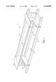
- FIG. 1 is a simplified perspective view of an exemplary housing comprising beams and side walls;
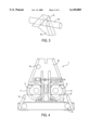
- FIG. 2 is a simplified perspective view of another exemplary housing comprising beams and side walls;
- FIG. 3 is an enlarged partial detail of FIG. 2;
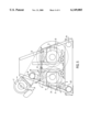
- FIG. 4 is a simplified front view of an exemplary housing with two recesses.
- FIG. 5 is a simplified front view of an exemplary housing with two recesses and a drive motor.
- FIG. 1 shows an exemplary housing (1) for one-sided roll mounting-and removal, particularly for mills, such as cracking mills, having three beams (two lower beams (2a) and an upper beam (2b)), an additional beam (2c) and two sidewalls (6a, 6b).
- the lower beams (2a) are connected transversely with each other through the sidewalls (6a, 6b).
- the other upper beams (2b, 2c) are also connected transversely with the side walls (6a, 6b), vertically spaced from the lower beams (2a).
- the length of the beams (2a, 2b, 2c) can be suitably longer than the length of the roll unit(s) (14, 15), shown in FIG. 4.
- Each roll unit(s) (14, 15) is placed in the direction of the arrow P1 in FIG. 1 towards the attachment (27), shown in FIG. 4, and fastened on the upper beams (2a), respectively removed therefrom.
- the side walls (6a, 6b) can be arranged in a such way that multiple housings (1) can be put together as a unitary structure, on top of each other, and/or back-to-back or in any combination. This arrangement can be used, for example, for a multi-stage cracking mill.
- FIG. 2 shows another exemplary housing (1') for two-sided roll mounting and removal, which can be used, for example as a flaking mill.
- the housing comprises two lower horizontal beams (4a) and an upper beam (4b) vertically spaced from the lower beams, whereby all three beams are connected with the side walls (8a, 8b).
- the two lower beams (4a) can be connected with each other through the lower parts (18', 19') of the side walls (8a, 8b), and the upper beam (4b) can be connected with the upper parts (18, 19) of the side walls (8a, 8b) accordingly.
- the sidewalls (8a, 8b) have two slots (11, 12) on each side for insertion of the rolls (14, 15), shown in FIG. 4, in the milling room.
- the slots (11, 12) located in the side walls (8a, 8b) can be arranged in a vicinity of the connecting piece (20).
- This connecting piece (20) connects upper parts and the lower parts (18, 18'; 19, 19) of the side walls (8a, 8b) with each other.
- the length of the beams (4a, 4b) can be longer than the length of the rolls (14, 15).
- the rolls can be placed separately onto the attachment (27), shown in FIG. 4, 5 and removed therefrom, in the direction of the arrows P2 and P3 in FIG. 2, on each side of the housing. That is, for example, one roll can be inserted in the direction of arrow P2 on one side of the housing while another roll can be removed from the other side in the direction of arrow P3.
- the rolls (14, 15) are available for handling during servicing so that only a defective roll can be removed without removing the other roll.
- FIG. 3 shows in detail an exemplary connection between the upper beam (4b) and the upper part (18) of the side wall (8a). It is particularly advantageous in this embodiment, that the beam (4b) is connected with the side wall (8a) in a such way that it passes through the wall or is fastened partly outside thereof. The same connection can also be provided for the lower beams (4a) and the lower parts (18', 19') of the sidewalls (8a, 8b). Therefore, a free access to the roll unit (14, 15) in FIG. 4 can be achieved.
- FIG. 4 shows the exemplary housing (1') of FIG. 2 in a frontal view.
- the rolls (14, 15) can, for example, both be removed from the housing through the recesses (11, 12) in the sidewalls (8a, 8b) in the same direction of the arrow P3 in FIG. 2.
- the lower beams (4a) can be provided as a direct support for a roll bearing (25). Alternately, the lower beams (4a) can accommodate an attachment (27) which in turn supports the roll bearing (25). It is particularly advantageous in this embodiment, that each roll (14, 15), respectively (i.e., a defective roll) can be removed separately from the housing (1').
- FIG. 5 shows a motor (17) arranged on the housing (1') and a motor base (26) arranged on the upper beams (4b) accordingly.
- the motor (17) is fastened pivotally on the motor base (26).
- This embodiment demands less basic ground space for the rolling mill and no ground space for the drive motors. Furthermore, the motor (17) is not affected by changing the rolls.
- the beams (4a, 4b) can also be provided as an attachment and/or a fastening for a transmission (24) and for a take-up device (28, 28') for transmission (24) between the rolls (14, 15), and for any panelling (e.g., protective panelling) and/or belt guards provided.
- Transmission rolls 21 can be placed into operative contact with the transmission 24 via the take-up devices (28, 28').
- the rolls (21) can be positioned stationarily or pivotally on the beams (4a, 4b).
- the housings 1 and 1', shown in FIG. 1 can be put together on top of each other, back-to-back and/or in any desired combination.
Landscapes
- Engineering & Computer Science (AREA)
- Mechanical Engineering (AREA)
- Food Science & Technology (AREA)
- Crushing And Grinding (AREA)
- Crushing And Pulverization Processes (AREA)
- Reduction Rolling/Reduction Stand/Operation Of Reduction Machine (AREA)
- Metal Rolling (AREA)
Priority Applications (8)
| Application Number | Priority Date | Filing Date | Title |
|---|---|---|---|
| US09/019,717 US6149085A (en) | 1998-02-06 | 1998-02-06 | Housing for a rolling mill |
| EP99100487A EP0935997B1 (de) | 1998-02-06 | 1999-01-12 | Walzenstuhlgehaüse |
| DK99100487T DK0935997T3 (da) | 1998-02-06 | 1999-01-12 | Hus til en valsemølle |
| ES99100487T ES2177140T3 (es) | 1998-02-06 | 1999-01-12 | Carcasa para molino giratorio. |
| AT99100487T ATE218923T1 (de) | 1998-02-06 | 1999-01-12 | Walzenstuhlgehaüse |
| DE69901739T DE69901739D1 (de) | 1998-02-06 | 1999-01-12 | Walzenstuhlgehaüse |
| BR9900741-0A BR9900741A (pt) | 1998-02-06 | 1999-02-05 | Carcaça para um moinho de rolos. |
| ARP990100497A AR018069A1 (es) | 1998-02-06 | 1999-02-05 | Alojamiento para un laminador |
Applications Claiming Priority (1)
| Application Number | Priority Date | Filing Date | Title |
|---|---|---|---|
| US09/019,717 US6149085A (en) | 1998-02-06 | 1998-02-06 | Housing for a rolling mill |
Publications (1)
| Publication Number | Publication Date |
|---|---|
| US6149085A true US6149085A (en) | 2000-11-21 |
Family
ID=21794654
Family Applications (1)
| Application Number | Title | Priority Date | Filing Date |
|---|---|---|---|
| US09/019,717 Expired - Lifetime US6149085A (en) | 1998-02-06 | 1998-02-06 | Housing for a rolling mill |
Country Status (8)
| Country | Link |
|---|---|
| US (1) | US6149085A (de) |
| EP (1) | EP0935997B1 (de) |
| AR (1) | AR018069A1 (de) |
| AT (1) | ATE218923T1 (de) |
| BR (1) | BR9900741A (de) |
| DE (1) | DE69901739D1 (de) |
| DK (1) | DK0935997T3 (de) |
| ES (1) | ES2177140T3 (de) |
Cited By (5)
| Publication number | Priority date | Publication date | Assignee | Title |
|---|---|---|---|---|
| US20060169148A1 (en) * | 2005-01-28 | 2006-08-03 | Emil Shultis | Apparatus for producing a beverage |
| DE102012000423A1 (de) * | 2012-01-12 | 2013-07-18 | Khd Humboldt Wedag Gmbh | Maschinenrahmen einer Hochdruckrollenpresse |
| CN104334278A (zh) * | 2012-04-20 | 2015-02-04 | 美卓矿物工业公司 | 用于高压辊压机的灰尘保护装置 |
| US20160339441A1 (en) * | 2015-05-21 | 2016-11-24 | Takraf Gmbh | Machinery frame for a roller crusher |
| US10933422B2 (en) * | 2018-06-19 | 2021-03-02 | Ecomill, Llc | Roller grain mill |
Families Citing this family (2)
| Publication number | Priority date | Publication date | Assignee | Title |
|---|---|---|---|---|
| DE102012009590C5 (de) * | 2012-05-11 | 2016-09-22 | Envipco Holding N.V. | Kompaktiervorrichtung für Leergut |
| DE102018116607A1 (de) * | 2018-07-10 | 2019-08-14 | Thyssenkrupp Ag | Walzenmühle |
Citations (6)
| Publication number | Priority date | Publication date | Assignee | Title |
|---|---|---|---|---|
| US344258A (en) * | 1886-06-22 | Teeeitoey | ||
| US1743911A (en) * | 1924-05-08 | 1930-01-14 | Pennsylvania Crusher Co | Frame for crushing machinery |
| US3899965A (en) * | 1973-02-06 | 1975-08-19 | Friedhelm Koch | Roll press |
| US4101083A (en) * | 1976-03-13 | 1978-07-18 | Buhler-Miag Gmbh | Housing for roll stands for grinding cereals or similar material |
| US4225093A (en) * | 1979-02-21 | 1980-09-30 | Buehler-Miag Gmbh | Rolling mill for milling cereals and similar material |
| US5813324A (en) * | 1997-11-06 | 1998-09-29 | Lin; A-Fang | Needle destruction device |
Family Cites Families (1)
| Publication number | Priority date | Publication date | Assignee | Title |
|---|---|---|---|---|
| FR2727638A1 (fr) * | 1994-12-02 | 1996-06-07 | Occidental Ind Realisations | Broyeur-finisseur de precision |
-
1998
- 1998-02-06 US US09/019,717 patent/US6149085A/en not_active Expired - Lifetime
-
1999
- 1999-01-12 ES ES99100487T patent/ES2177140T3/es not_active Expired - Lifetime
- 1999-01-12 DE DE69901739T patent/DE69901739D1/de not_active Expired - Lifetime
- 1999-01-12 AT AT99100487T patent/ATE218923T1/de not_active IP Right Cessation
- 1999-01-12 EP EP99100487A patent/EP0935997B1/de not_active Expired - Lifetime
- 1999-01-12 DK DK99100487T patent/DK0935997T3/da active
- 1999-02-05 AR ARP990100497A patent/AR018069A1/es active IP Right Grant
- 1999-02-05 BR BR9900741-0A patent/BR9900741A/pt not_active IP Right Cessation
Patent Citations (7)
| Publication number | Priority date | Publication date | Assignee | Title |
|---|---|---|---|---|
| US344258A (en) * | 1886-06-22 | Teeeitoey | ||
| US1743911A (en) * | 1924-05-08 | 1930-01-14 | Pennsylvania Crusher Co | Frame for crushing machinery |
| US3899965A (en) * | 1973-02-06 | 1975-08-19 | Friedhelm Koch | Roll press |
| US4101083A (en) * | 1976-03-13 | 1978-07-18 | Buhler-Miag Gmbh | Housing for roll stands for grinding cereals or similar material |
| GB1524792A (en) * | 1976-03-13 | 1978-09-13 | Buehler Miag Gmbh | Roll frame for a roller mill for milling cereals and like feeds |
| US4225093A (en) * | 1979-02-21 | 1980-09-30 | Buehler-Miag Gmbh | Rolling mill for milling cereals and similar material |
| US5813324A (en) * | 1997-11-06 | 1998-09-29 | Lin; A-Fang | Needle destruction device |
Cited By (7)
| Publication number | Priority date | Publication date | Assignee | Title |
|---|---|---|---|---|
| US20060169148A1 (en) * | 2005-01-28 | 2006-08-03 | Emil Shultis | Apparatus for producing a beverage |
| DE102012000423A1 (de) * | 2012-01-12 | 2013-07-18 | Khd Humboldt Wedag Gmbh | Maschinenrahmen einer Hochdruckrollenpresse |
| DE102012000423B4 (de) * | 2012-01-12 | 2017-05-24 | Khd Humboldt Wedag Gmbh | Maschinenrahmen einer Hochdruckrollenpresse |
| CN104334278A (zh) * | 2012-04-20 | 2015-02-04 | 美卓矿物工业公司 | 用于高压辊压机的灰尘保护装置 |
| US20160339441A1 (en) * | 2015-05-21 | 2016-11-24 | Takraf Gmbh | Machinery frame for a roller crusher |
| US10307764B2 (en) * | 2015-05-21 | 2019-06-04 | Takraf Gmbh | Machinery frame for a roller crusher |
| US10933422B2 (en) * | 2018-06-19 | 2021-03-02 | Ecomill, Llc | Roller grain mill |
Also Published As
| Publication number | Publication date |
|---|---|
| AR018069A1 (es) | 2001-10-31 |
| DK0935997T3 (da) | 2002-09-23 |
| EP0935997A1 (de) | 1999-08-18 |
| EP0935997B1 (de) | 2002-06-12 |
| ES2177140T3 (es) | 2002-12-01 |
| BR9900741A (pt) | 1999-12-21 |
| ATE218923T1 (de) | 2002-06-15 |
| DE69901739D1 (de) | 2002-07-18 |
Similar Documents
| Publication | Publication Date | Title |
|---|---|---|
| US6149085A (en) | Housing for a rolling mill | |
| EP0165673B1 (de) | Einadriges Walzwerk in Blockbauart | |
| US4101083A (en) | Housing for roll stands for grinding cereals or similar material | |
| RU2118920C1 (ru) | Правильная машина, в частности для правки листов и полос | |
| US8051693B2 (en) | Device for mounting and functional verification of roll fittings in rolling mill stands or rolling mill trains such as, e.g., tandem rolling mill trains | |
| EP0911090A3 (de) | Walzenaustauschverfahren und System für ein Walzgerüst ohne Einbaustücke | |
| JPH01502891A (ja) | ハウジング構造 | |
| US20020046589A1 (en) | Leveler for stretcher leveling of a metal strip or sheet | |
| CA2364069A1 (en) | A rolling mill with roll deflection bi-dimensionally controlled | |
| CN217432651U (zh) | 一种汽车零部件原件加工用给料装置 | |
| JP2006136919A (ja) | 両持ち式圧延機 | |
| CN214939348U (zh) | 一种用于斜拉索展索导向的装置 | |
| US5187960A (en) | Apparatus for supporting reduction rolls in a rolling mill | |
| SE9403747L (sv) | Horisontal-vertikalvalsverk | |
| CN223043310U (zh) | 用于沿着轧制轴线轧制金属棒材、线材或管材的轧机 | |
| US4319475A (en) | Center-spine mounted tandem cantilevered rolling mill | |
| US3316746A (en) | Multiple-stand rolling mill | |
| SE527250C2 (sv) | Stativ för en dubbelvirapress och metod för virabyte i en dubbelvirapress innefattande nämnda stativ | |
| CN218611102U (zh) | 一种多辊钢板矫正机结构 | |
| RU2179901C2 (ru) | Машина для правки листового проката | |
| JPH0819803A (ja) | ブロック式圧延機 | |
| ATE149060T1 (de) | Gerüstständer | |
| JPH0312972B2 (de) | ||
| RU2100116C1 (ru) | Машина для правки листового проката | |
| US20250235970A1 (en) | Machine tool |
Legal Events
| Date | Code | Title | Description |
|---|---|---|---|
| AS | Assignment |
Owner name: BUHLER AG, SWITZERLAND Free format text: ASSIGNMENT OF ASSIGNORS INTEREST;ASSIGNORS:FETZER, WILHELM;KELLER, URS V.;REEL/FRAME:008971/0421;SIGNING DATES FROM 19980130 TO 19980202 |
|
| STCF | Information on status: patent grant |
Free format text: PATENTED CASE |
|
| FEPP | Fee payment procedure |
Free format text: PAYOR NUMBER ASSIGNED (ORIGINAL EVENT CODE: ASPN); ENTITY STATUS OF PATENT OWNER: LARGE ENTITY |
|
| FPAY | Fee payment |
Year of fee payment: 4 |
|
| FPAY | Fee payment |
Year of fee payment: 8 |
|
| FEPP | Fee payment procedure |
Free format text: PAYER NUMBER DE-ASSIGNED (ORIGINAL EVENT CODE: RMPN); ENTITY STATUS OF PATENT OWNER: LARGE ENTITY Free format text: PAYOR NUMBER ASSIGNED (ORIGINAL EVENT CODE: ASPN); ENTITY STATUS OF PATENT OWNER: LARGE ENTITY |
|
| FPAY | Fee payment |
Year of fee payment: 12 |