EP0935997B1 - Walzenstuhlgehaüse - Google Patents
Walzenstuhlgehaüse Download PDFInfo
- Publication number
- EP0935997B1 EP0935997B1 EP99100487A EP99100487A EP0935997B1 EP 0935997 B1 EP0935997 B1 EP 0935997B1 EP 99100487 A EP99100487 A EP 99100487A EP 99100487 A EP99100487 A EP 99100487A EP 0935997 B1 EP0935997 B1 EP 0935997B1
- Authority
- EP
- European Patent Office
- Prior art keywords
- housing
- beams
- roll
- side walls
- further beam
- Prior art date
- Legal status (The legal status is an assumption and is not a legal conclusion. Google has not performed a legal analysis and makes no representation as to the accuracy of the status listed.)
- Expired - Lifetime
Links
- 238000005096 rolling process Methods 0.000 title claims description 12
- 238000010276 construction Methods 0.000 claims description 10
- 230000005540 biological transmission Effects 0.000 claims description 8
- 238000005336 cracking Methods 0.000 claims description 4
- 238000000227 grinding Methods 0.000 claims description 3
- 239000002184 metal Substances 0.000 claims description 3
- 230000004308 accommodation Effects 0.000 claims 1
- 238000003801 milling Methods 0.000 description 3
- 230000002950 deficient Effects 0.000 description 2
- 235000013339 cereals Nutrition 0.000 description 1
- 230000037431 insertion Effects 0.000 description 1
- 238000003780 insertion Methods 0.000 description 1
- 230000001681 protective effect Effects 0.000 description 1
Images


Classifications
-
- B—PERFORMING OPERATIONS; TRANSPORTING
- B30—PRESSES
- B30B—PRESSES IN GENERAL
- B30B15/00—Details of, or accessories for, presses; Auxiliary measures in connection with pressing
- B30B15/04—Frames; Guides
-
- B—PERFORMING OPERATIONS; TRANSPORTING
- B02—CRUSHING, PULVERISING, OR DISINTEGRATING; PREPARATORY TREATMENT OF GRAIN FOR MILLING
- B02C—CRUSHING, PULVERISING, OR DISINTEGRATING IN GENERAL; MILLING GRAIN
- B02C4/00—Crushing or disintegrating by roller mills
- B02C4/28—Details
Definitions
- the present invention relates to a housing for a mill for milling cereals and other goods, and including a carrying frame to accommodate a roll unit, or plural rolls separately on attachments.
- Housings for rolling mills are typically casted constructions, welded metal sheets, profile construction or any combination of these constructions, for separately accommodating the bearings of rolls or a roll unit onto sidewalls.
- a lateral exchange of roll units is disclosed, i.e. exchange in the direction of the longitudinal axis of the rolls.
- a free lateral space next to the machine housing sized according to the length of the rolls is provided.
- a rolling mill with three roll units needs relatively large spaces between the rolls and considerably more surface for carrying out the exchange and for rebuilding the rolling mill.
- the rolling mill also comprises a complicated and expensive housing construction. This construction includes four horizontal beams carrying the roll units with three further transverse members. There are also provided additional support plates mounted on the upper face on the horizontal beams for the bearings of the roll units.
- the main disadvantage of this arrangement is the two vertical, square frames increase the total costs of the housing.
- the access to the roll unit, particularly its detachment from the drive and removal from the housing, is more difficult, because the frames (from the front side) extend beyond the sidewalls.
- the costs of the housing are increased by an arrangement of a back wall being screwed with the frame and two horizontal beams.
- a housing for a rolling mill comprises two side walls, which are casted or welded metal sheet or profile construction, or any combination of these constructions, with at least two horizontal beams to accommodate the rolls or the roll unit.
- the housing is characterized in having at least one further beam vertically spaced from the horizontal beams, whereby the beams extend through the side walls or are fastened partly outside thereof.
- a further additional beam in a vertical spacing to the horizontal beams can also be provided.
- three horizontal beams can be used.
- the frame beams can be made suitably as, for example, hollow profiles and can be screwed or welded with the sidewalls.
- the bearings of the rolls can be placed advantageously directly onto the beams or indirectly onto supporting plates connected with the corresponding beams.
- the sidewalls can have suitable slots for mounting of the roll unit(s).
- the sidewalls can, for example, have two slots so that each roll can be mounted from either side.
- the beams and the sidewalls can have slots and holes, and can have connecting and fastening means.
- the beams can be provided as a direct support for the roll bearing.
- the beams can also be provided as a support for an attachment of the roll bearings.
- the beams can be provided as a support or a fastening for the transmission pulley and for a take-up device for the transmission between the rolls.
- the beams can also be provided as a support and/or a fastening for the motor base.
- the beams can also be provided as a support and/or a fastening for any panelling and any belt guards.
- Housings can be mounted on top of each other and/or back-to-back or in any other combination forming a multi-stage roller mill.
- a roll grinding and turning device for servicing the roll surface can be provided on the beams.
- a roll mounting-and-removing device for servicing the rolls can also be provided on the beams.
- a housing with side walls having, for example, one slot can be provided for a cracking mill.
- a housing with sidewalls having, for example, two slots can be provided for a rolling mill for a flaking mill.
- Fig. 1 shows an exemplary housing (1) for one-sided roll mounting-and removal, particularly for mills, such as cracking mills, having three beams (two lower beams (2a) and an upper beam (2b)), an additional beam (2c) and two sidewalls (6a, 6b).
- the lower beams (2a) are connected transversely with each other through the sidewalls (6a, 6b).
- the other upper beams (2b, 2c) are also connected transversely with the side walls (6a, 6b), vertically spaced from the lower beams (2a).
- the length of the beams (2a, 2b, 2c) can be suitably longer than the length of the roll unit(s) (14, 15), shown in Fig. 4.
- Each roll unit(s) (14, 15) is placed in the direction of the arrow P1 in Fig. 1 towards the attachment (27), shown in Fig. 4, and fastened on the upper beams (2a), respectively removed therefrom.
- the side walls (6a, 6b) can be arranged in a such way that multiple housings (1) can be put together as a unitary structure, on top of each other, and/or back-to-back or in any combination. This arrangement can be used, for example, for a multi-stage cracking mill.
- Fig. 2 shows another exemplary housing (1') for two-sided roll mounting and removal, which can be used, for example as a flaking mill.
- the housing comprises two lower horizontal beams (4a) and an upper beam (4b) vertically spaced from the lower beams, whereby all three beams are connected with the side walls (8a, 8b).
- the two lower beams (4a) can be connected with each other through the lower parts (18', 19') of the side walls (8a, 8b), and the upper beam (4b) can be connected with the upper parts (18, 19) of the side walls (8a, 8b) accordingly.
- the sidewalls (8a, 8b) have two slots (11, 12) on each side for insertion of the rolls (14, 15), shown in Fig. 4, in the milling room.
- the slots (11, 12) located in the side walls (8a, 8b) can be arranged in a vicinity of the connecting piece (20).
- This connecting piece (20) connects upper parts and the lower parts (18, 18'; 19, 19) of the side walls (8a, 8b) with each other.
- the length of the beams (4a, 4b) can be longer than the length of the rolls (14, 15).
- the rolls can be placed separately onto the attachment (27), shown in Fig. 4, 5 and removed therefrom, in the direction of the arrows P2 and P3 in Fig. 2, on each side of the housing. That is, for example, one roll can be inserted in the direction of arrow P2 on one side of the housing while another roll can be removed from the other side in the direction of arrow P3.
- the rolls (14, 15) are available for handling during servicing so that only a defective roll can be removed without removing the other roll.
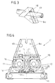
- Fig. 3 shows in detail an exemplary connection between the upper beam (4b) and the upper part (18) of the side wall (8a). It is particularly advantageous in this embodiment, that the beam (4b) is connected with the side wall (8a) in a such way that it passes through the wall or is fastened partly outside thereof. The same connection can also be provided for the lower beams (4a) and the lower parts (18', 19') of the sidewalls (8a, 8b). Therefore, a free access to the roll unit (14, 15) in Fig. 4 can be achieved.
- Fig. 4 shows the exemplary housing (1') of Fig. 2 in a frontal view.
- the rolls (14, 15) can, for example, both be removed from the housing through the recesses (11, 12) in the sidewalls (8a, 8b) in the same direction of the arrow P3 in Fig. 2.
- the lower beams (4a) can be provided as a direct support for a roll bearing (25). Alternately, the lower beams (4a) can accommodate an attachment (27) which in turn supports the roll bearing (25). It is particularly advantageous in this embodiment, that each roll (14, 15), respectively (i.e., a defective roll) can be removed separately from the housing (1').
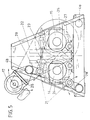
- Fig. 5 shows a motor (17) arranged on the housing (1') and a motor base (26) arranged on the upper beams (4b) accordingly.
- the motor (17) is fastened pivotally on the motor base (26).
- This embodiment demands less basic ground space for the rolling mill and no ground space for the drive motors. Furthermore, the motor (17) is not affected by changing the rolls.
- the beams (4a, 4b) can also be provided as an attachment and/or a fastening for a transmission (24) and for a take-up device (28, 28') for transmission (24) between the rolls (14, 15), and for any panelling (e.g., protective panelling) and/or belt guards provided.
- Transmission rolls 21 can be placed into operative contact with the transmission 24 via the take-up devices (28, 28').
- the rolls (21) can be positioned stationarily or pivotally on the beams (4a, 4b).
- the housings 1 and 1', shown in Fig. 1 can be put together on top of each other, back-to-back and/or in any desired combination.
Landscapes
- Engineering & Computer Science (AREA)
- Mechanical Engineering (AREA)
- Food Science & Technology (AREA)
- Crushing And Grinding (AREA)
- Crushing And Pulverization Processes (AREA)
- Reduction Rolling/Reduction Stand/Operation Of Reduction Machine (AREA)
- Metal Rolling (AREA)
Claims (17)
- Gehäuse (1) für ein Walzwerk, umfassend:zwei Seitenwände, welche mindestens zwei horizontale Träger zur Aufnahme von mindestens einer Walze enthalten; undmindestens einen weiteren Träger, welcher vertikal, entfernt von den mindestens zwei horizontalen Trägern (2a) angeordnet ist, wobei die mindestens zwei horizontalen Träger an den zwei Seitenwänden (6a, 6b) durch eine Anordnung angebracht sind, welche mindestens enthält:Verlaufen der mindestens zwei horizontalen Träger durch die zwei Seitenwände; oderteilweises Anordnen und Befestigen der mindestens zwei horizontalen Trägern außerhalb der Seitenwände.
- Gehäuse nach Anspruch 1, wobei die zwei Seitenwände aus mindestens einem Bestandteil einer Gruppe gebildet werden, welche umfaßt:Gußkonstruktion, Metallschweißbahnen, Profilkonstruktion und eine Kombination dieser Konstruktionen.
- Gehäuse nach Anspruch 1, wobei mindestens zwei horizontale Träger vorgesehen sind.
- Gehäuse nach Anspruch 1, wobei die mindestens zwei horizontalen Träger und der mindestens eine weitere Träger aus Hohlprofilen gebildet sind und mit den Seitenwänden verschraubt oder verschweißt sind.
- Gehäuse nach Anspruch 1, wobei die Seitenwände einen Schlitz zur Unterbringung der mindestens einen Walze aufweisen.
- Gehäuse nach Anspruch 5, wobei die Seitenwände zwei Schlitze zur separaten Unterbringung von mindestens zwei Walzen aufweisen.
- Gehäuse nach Anspruch 1, wobei die Seitenwände, die mindestens zwei Träger und der weitere Träger Schlitze und Aussparungen und Verbindungs- und Befestigungsmittel aufweisen.
- Gehäuse nach Anspruch 1, wobei die mindestens zwei Träger eine direkte Befestigung eines Walzenlagers vorsehen.
- Gehäuse nach Anspruch 1, wobei die mindestens zwei Träger eine Befestigung zum indirekten Halten eines Walzenlagers enthalten.
- Gehäuse nach Anspruch 9, wobei die mindestens zwei Träger und der mindestens eine weitere Träger mindestens eine Halterung oder eine Befestigung für Antriebswalzen und für eine Nachstellvorrichtung für den Antrieb zwischen mehrfachen Walzen vorsehen.
- Gehäuse nach Anspruch 7, wobei der mindestens eine weitere Träger mindestens eine Halterung oder eine Befestigung für einen Motorblock vorsieht.
- Gehäuse nach Anspruch 10, wobei die mindestens zwei Träger und der mindestens eine weitere Träger mindestens eine Halterung oder eine Befestigung für eine Verkleidung und Riemenschutze vorsehen.
- Gehäuse nach Anspruch 1, welches mehrfache Gehäuse umfaßt, die in einer Anordnung angebracht sind, welche aus einer Gruppe ausgewählt ist, die umfaßt:Rückseite an Rückseite, eines auf dem anderen und jede Kombination dieser Anordnungen.
- Gehäuse nach Anspruch 11, ferner umfassend:mindestens eine Mahlvorrichtung oder eine Drehvorrichtung zur Wartung, wobei die mindestens eine Mahlvorrichtung oder Drehvorrichtung auf den mindestens zwei Trägern und dem weiteren Träger vorgesehen ist.
- Gehäuse nach Anspruch 12, ferner umfassend:eine Wartungsvorrichtung zum Anbringen und Abnehmen der Walzen, wobei die Wartungsvorrichtung zum Anbringen und Abnehmen der Walzen auf den mindestens zwei Trägern und dem weiteren Träger vorgesehen ist.
- Gehäuse nach Anspruch 1, wobei das Gehäuse ein Walzwerkgehäuse zum Cracken ist.
- Gehäuse nach Anspruch 1, wobei das Gehäuse ein Walzwerkgehäuse zum Flockieren ist.
Applications Claiming Priority (2)
| Application Number | Priority Date | Filing Date | Title |
|---|---|---|---|
| US09/019,717 US6149085A (en) | 1998-02-06 | 1998-02-06 | Housing for a rolling mill |
| US19717 | 1998-02-06 |
Publications (2)
| Publication Number | Publication Date |
|---|---|
| EP0935997A1 EP0935997A1 (de) | 1999-08-18 |
| EP0935997B1 true EP0935997B1 (de) | 2002-06-12 |
Family
ID=21794654
Family Applications (1)
| Application Number | Title | Priority Date | Filing Date |
|---|---|---|---|
| EP99100487A Expired - Lifetime EP0935997B1 (de) | 1998-02-06 | 1999-01-12 | Walzenstuhlgehaüse |
Country Status (8)
| Country | Link |
|---|---|
| US (1) | US6149085A (de) |
| EP (1) | EP0935997B1 (de) |
| AR (1) | AR018069A1 (de) |
| AT (1) | ATE218923T1 (de) |
| BR (1) | BR9900741A (de) |
| DE (1) | DE69901739D1 (de) |
| DK (1) | DK0935997T3 (de) |
| ES (1) | ES2177140T3 (de) |
Families Citing this family (7)
| Publication number | Priority date | Publication date | Assignee | Title |
|---|---|---|---|---|
| US7555979B2 (en) * | 2005-01-28 | 2009-07-07 | Emil Shultis | Apparatus for producing a beverage |
| DE102012000423B4 (de) * | 2012-01-12 | 2017-05-24 | Khd Humboldt Wedag Gmbh | Maschinenrahmen einer Hochdruckrollenpresse |
| US20130277477A1 (en) * | 2012-04-20 | 2013-10-24 | Metso Minerals Industries, Inc. | Dust protection for hpgr |
| DE102012009590C5 (de) * | 2012-05-11 | 2016-09-22 | Envipco Holding N.V. | Kompaktiervorrichtung für Leergut |
| DE102015209280A1 (de) * | 2015-05-21 | 2016-11-24 | Takraf Gmbh | Maschinenrahmen für einen Walzenbrecher |
| US10933422B2 (en) * | 2018-06-19 | 2021-03-02 | Ecomill, Llc | Roller grain mill |
| DE102018116607A1 (de) * | 2018-07-10 | 2019-08-14 | Thyssenkrupp Ag | Walzenmühle |
Family Cites Families (7)
| Publication number | Priority date | Publication date | Assignee | Title |
|---|---|---|---|---|
| US344258A (en) * | 1886-06-22 | Teeeitoey | ||
| US1743911A (en) * | 1924-05-08 | 1930-01-14 | Pennsylvania Crusher Co | Frame for crushing machinery |
| DE2305626C3 (de) * | 1973-02-06 | 1978-03-09 | Maschinenfabrik Koeppern Gmbh & Co Kg, 4320 Hattingen | Zweiwalzenpresse mit nebeneinanderliegenden Walzen |
| DE2610742C3 (de) | 1976-03-13 | 1979-06-28 | Buehler-Miag Gmbh, 3300 Braunschweig | Gehäuse für Walzenstühle zum Vermählen von Cerealien und anderem Gut |
| US4225093A (en) * | 1979-02-21 | 1980-09-30 | Buehler-Miag Gmbh | Rolling mill for milling cereals and similar material |
| FR2727638A1 (fr) * | 1994-12-02 | 1996-06-07 | Occidental Ind Realisations | Broyeur-finisseur de precision |
| US5813324A (en) * | 1997-11-06 | 1998-09-29 | Lin; A-Fang | Needle destruction device |
-
1998
- 1998-02-06 US US09/019,717 patent/US6149085A/en not_active Expired - Lifetime
-
1999
- 1999-01-12 ES ES99100487T patent/ES2177140T3/es not_active Expired - Lifetime
- 1999-01-12 DE DE69901739T patent/DE69901739D1/de not_active Expired - Lifetime
- 1999-01-12 AT AT99100487T patent/ATE218923T1/de not_active IP Right Cessation
- 1999-01-12 EP EP99100487A patent/EP0935997B1/de not_active Expired - Lifetime
- 1999-01-12 DK DK99100487T patent/DK0935997T3/da active
- 1999-02-05 AR ARP990100497A patent/AR018069A1/es active IP Right Grant
- 1999-02-05 BR BR9900741-0A patent/BR9900741A/pt not_active IP Right Cessation
Also Published As
| Publication number | Publication date |
|---|---|
| AR018069A1 (es) | 2001-10-31 |
| US6149085A (en) | 2000-11-21 |
| DK0935997T3 (da) | 2002-09-23 |
| EP0935997A1 (de) | 1999-08-18 |
| ES2177140T3 (es) | 2002-12-01 |
| BR9900741A (pt) | 1999-12-21 |
| ATE218923T1 (de) | 2002-06-15 |
| DE69901739D1 (de) | 2002-07-18 |
Similar Documents
| Publication | Publication Date | Title |
|---|---|---|
| EP0935997B1 (de) | Walzenstuhlgehaüse | |
| EP0165673B1 (de) | Einadriges Walzwerk in Blockbauart | |
| RU2118920C1 (ru) | Правильная машина, в частности для правки листов и полос | |
| US8051693B2 (en) | Device for mounting and functional verification of roll fittings in rolling mill stands or rolling mill trains such as, e.g., tandem rolling mill trains | |
| CN218966662U (zh) | 牵引电池车辆底板 | |
| EP0911090A3 (de) | Walzenaustauschverfahren und System für ein Walzgerüst ohne Einbaustücke | |
| JPS58199608A (ja) | 連続圧延設備 | |
| JPH01502891A (ja) | ハウジング構造 | |
| CA2364069A1 (en) | A rolling mill with roll deflection bi-dimensionally controlled | |
| US20020046589A1 (en) | Leveler for stretcher leveling of a metal strip or sheet | |
| CN217432651U (zh) | 一种汽车零部件原件加工用给料装置 | |
| JP2006136919A (ja) | 両持ち式圧延機 | |
| KR20010064839A (ko) | 소둔로 롤 교체장치 | |
| CN214939348U (zh) | 一种用于斜拉索展索导向的装置 | |
| US5187960A (en) | Apparatus for supporting reduction rolls in a rolling mill | |
| SE9403747L (sv) | Horisontal-vertikalvalsverk | |
| CN223043310U (zh) | 用于沿着轧制轴线轧制金属棒材、线材或管材的轧机 | |
| US4319475A (en) | Center-spine mounted tandem cantilevered rolling mill | |
| SE527250C2 (sv) | Stativ för en dubbelvirapress och metod för virabyte i en dubbelvirapress innefattande nämnda stativ | |
| JP5247541B2 (ja) | 形鋼用多列圧延装置 | |
| US3316746A (en) | Multiple-stand rolling mill | |
| CN218611102U (zh) | 一种多辊钢板矫正机结构 | |
| JP2022098946A (ja) | 遊技機島の構造体 | |
| RU2179901C2 (ru) | Машина для правки листового проката | |
| TWI839065B (zh) | 輥軋機、冷軋方法和鋼板製造方法 |
Legal Events
| Date | Code | Title | Description |
|---|---|---|---|
| PUAI | Public reference made under article 153(3) epc to a published international application that has entered the european phase |
Free format text: ORIGINAL CODE: 0009012 |
|
| AK | Designated contracting states |
Kind code of ref document: A1 Designated state(s): AT BE CH DE DK ES FR GB IT LI NL |
|
| AX | Request for extension of the european patent |
Free format text: AL;LT;LV;MK;RO;SI |
|
| 17P | Request for examination filed |
Effective date: 19991014 |
|
| AKX | Designation fees paid |
Free format text: AT BE CH DE DK ES FR GB IT LI NL |
|
| GRAG | Despatch of communication of intention to grant |
Free format text: ORIGINAL CODE: EPIDOS AGRA |
|
| 17Q | First examination report despatched |
Effective date: 20010904 |
|
| GRAG | Despatch of communication of intention to grant |
Free format text: ORIGINAL CODE: EPIDOS AGRA |
|
| GRAH | Despatch of communication of intention to grant a patent |
Free format text: ORIGINAL CODE: EPIDOS IGRA |
|
| GRAH | Despatch of communication of intention to grant a patent |
Free format text: ORIGINAL CODE: EPIDOS IGRA |
|
| GRAA | (expected) grant |
Free format text: ORIGINAL CODE: 0009210 |
|
| AK | Designated contracting states |
Kind code of ref document: B1 Designated state(s): AT BE CH DE DK ES FR GB IT LI NL |
|
| REF | Corresponds to: |
Ref document number: 218923 Country of ref document: AT Date of ref document: 20020615 Kind code of ref document: T |
|
| REG | Reference to a national code |
Ref country code: GB Ref legal event code: FG4D |
|
| REG | Reference to a national code |
Ref country code: CH Ref legal event code: EP |
|
| REF | Corresponds to: |
Ref document number: 69901739 Country of ref document: DE Date of ref document: 20020718 |
|
| PG25 | Lapsed in a contracting state [announced via postgrant information from national office to epo] |
Ref country code: DE Free format text: LAPSE BECAUSE OF FAILURE TO SUBMIT A TRANSLATION OF THE DESCRIPTION OR TO PAY THE FEE WITHIN THE PRESCRIBED TIME-LIMIT Effective date: 20020913 |
|
| REG | Reference to a national code |
Ref country code: DK Ref legal event code: T3 |
|
| REG | Reference to a national code |
Ref country code: ES Ref legal event code: FG2A Ref document number: 2177140 Country of ref document: ES Kind code of ref document: T3 |
|
| PLBE | No opposition filed within time limit |
Free format text: ORIGINAL CODE: 0009261 |
|
| STAA | Information on the status of an ep patent application or granted ep patent |
Free format text: STATUS: NO OPPOSITION FILED WITHIN TIME LIMIT |
|
| 26N | No opposition filed |
Effective date: 20030313 |
|
| PGFP | Annual fee paid to national office [announced via postgrant information from national office to epo] |
Ref country code: AT Payment date: 20061212 Year of fee payment: 9 |
|
| PGFP | Annual fee paid to national office [announced via postgrant information from national office to epo] |
Ref country code: GB Payment date: 20061213 Year of fee payment: 9 |
|
| PGFP | Annual fee paid to national office [announced via postgrant information from national office to epo] |
Ref country code: DK Payment date: 20071218 Year of fee payment: 10 |
|
| GBPC | Gb: european patent ceased through non-payment of renewal fee |
Effective date: 20080112 |
|
| PG25 | Lapsed in a contracting state [announced via postgrant information from national office to epo] |
Ref country code: AT Free format text: LAPSE BECAUSE OF NON-PAYMENT OF DUE FEES Effective date: 20080112 |
|
| PG25 | Lapsed in a contracting state [announced via postgrant information from national office to epo] |
Ref country code: GB Free format text: LAPSE BECAUSE OF NON-PAYMENT OF DUE FEES Effective date: 20080112 |
|
| PGFP | Annual fee paid to national office [announced via postgrant information from national office to epo] |
Ref country code: CH Payment date: 20081212 Year of fee payment: 11 |
|
| PGFP | Annual fee paid to national office [announced via postgrant information from national office to epo] |
Ref country code: ES Payment date: 20090123 Year of fee payment: 11 |
|
| PGFP | Annual fee paid to national office [announced via postgrant information from national office to epo] |
Ref country code: NL Payment date: 20090113 Year of fee payment: 11 |
|
| PGFP | Annual fee paid to national office [announced via postgrant information from national office to epo] |
Ref country code: IT Payment date: 20090114 Year of fee payment: 11 |
|
| REG | Reference to a national code |
Ref country code: DK Ref legal event code: EBP |
|
| PGFP | Annual fee paid to national office [announced via postgrant information from national office to epo] |
Ref country code: FR Payment date: 20090106 Year of fee payment: 11 |
|
| PG25 | Lapsed in a contracting state [announced via postgrant information from national office to epo] |
Ref country code: DK Free format text: LAPSE BECAUSE OF NON-PAYMENT OF DUE FEES Effective date: 20090731 |
|
| REG | Reference to a national code |
Ref country code: NL Ref legal event code: V1 Effective date: 20100801 |
|
| REG | Reference to a national code |
Ref country code: CH Ref legal event code: PL |
|
| REG | Reference to a national code |
Ref country code: FR Ref legal event code: ST Effective date: 20100930 |
|
| PG25 | Lapsed in a contracting state [announced via postgrant information from national office to epo] |
Ref country code: NL Free format text: LAPSE BECAUSE OF NON-PAYMENT OF DUE FEES Effective date: 20100801 Ref country code: LI Free format text: LAPSE BECAUSE OF NON-PAYMENT OF DUE FEES Effective date: 20100131 Ref country code: FR Free format text: LAPSE BECAUSE OF NON-PAYMENT OF DUE FEES Effective date: 20100201 Ref country code: CH Free format text: LAPSE BECAUSE OF NON-PAYMENT OF DUE FEES Effective date: 20100131 |
|
| PG25 | Lapsed in a contracting state [announced via postgrant information from national office to epo] |
Ref country code: IT Free format text: LAPSE BECAUSE OF NON-PAYMENT OF DUE FEES Effective date: 20100112 |
|
| REG | Reference to a national code |
Ref country code: ES Ref legal event code: FD2A Effective date: 20110401 |
|
| PG25 | Lapsed in a contracting state [announced via postgrant information from national office to epo] |
Ref country code: ES Free format text: LAPSE BECAUSE OF NON-PAYMENT OF DUE FEES Effective date: 20110321 |
|
| PG25 | Lapsed in a contracting state [announced via postgrant information from national office to epo] |
Ref country code: ES Free format text: LAPSE BECAUSE OF NON-PAYMENT OF DUE FEES Effective date: 20100113 |
|
| PGFP | Annual fee paid to national office [announced via postgrant information from national office to epo] |
Ref country code: BE Payment date: 20180124 Year of fee payment: 20 |
|
| REG | Reference to a national code |
Ref country code: BE Ref legal event code: MK Effective date: 20190112 |