US6149423A - Hot channel injection moulding die - Google Patents
Hot channel injection moulding die Download PDFInfo
- Publication number
- US6149423A US6149423A US08/930,849 US93084997A US6149423A US 6149423 A US6149423 A US 6149423A US 93084997 A US93084997 A US 93084997A US 6149423 A US6149423 A US 6149423A
- Authority
- US
- United States
- Prior art keywords
- hot channel
- molding die
- injection molding
- hollow space
- channel injection
- Prior art date
- Legal status (The legal status is an assumption and is not a legal conclusion. Google has not performed a legal analysis and makes no representation as to the accuracy of the status listed.)
- Expired - Lifetime
Links
Images

Classifications
-
- B—PERFORMING OPERATIONS; TRANSPORTING
- B29—WORKING OF PLASTICS; WORKING OF SUBSTANCES IN A PLASTIC STATE IN GENERAL
- B29C—SHAPING OR JOINING OF PLASTICS; SHAPING OF MATERIAL IN A PLASTIC STATE, NOT OTHERWISE PROVIDED FOR; AFTER-TREATMENT OF THE SHAPED PRODUCTS, e.g. REPAIRING
- B29C45/00—Injection moulding, i.e. forcing the required volume of moulding material through a nozzle into a closed mould; Apparatus therefor
- B29C45/17—Component parts, details or accessories; Auxiliary operations
- B29C45/26—Moulds
- B29C45/27—Sprue channels ; Runner channels or runner nozzles
- B29C45/2737—Heating or cooling means therefor
-
- B—PERFORMING OPERATIONS; TRANSPORTING
- B29—WORKING OF PLASTICS; WORKING OF SUBSTANCES IN A PLASTIC STATE IN GENERAL
- B29C—SHAPING OR JOINING OF PLASTICS; SHAPING OF MATERIAL IN A PLASTIC STATE, NOT OTHERWISE PROVIDED FOR; AFTER-TREATMENT OF THE SHAPED PRODUCTS, e.g. REPAIRING
- B29C45/00—Injection moulding, i.e. forcing the required volume of moulding material through a nozzle into a closed mould; Apparatus therefor
- B29C45/17—Component parts, details or accessories; Auxiliary operations
- B29C45/26—Moulds
- B29C45/27—Sprue channels ; Runner channels or runner nozzles
- B29C45/2725—Manifolds
-
- B—PERFORMING OPERATIONS; TRANSPORTING
- B29—WORKING OF PLASTICS; WORKING OF SUBSTANCES IN A PLASTIC STATE IN GENERAL
- B29C—SHAPING OR JOINING OF PLASTICS; SHAPING OF MATERIAL IN A PLASTIC STATE, NOT OTHERWISE PROVIDED FOR; AFTER-TREATMENT OF THE SHAPED PRODUCTS, e.g. REPAIRING
- B29C45/00—Injection moulding, i.e. forcing the required volume of moulding material through a nozzle into a closed mould; Apparatus therefor
- B29C45/17—Component parts, details or accessories; Auxiliary operations
- B29C45/26—Moulds
- B29C45/27—Sprue channels ; Runner channels or runner nozzles
- B29C45/2737—Heating or cooling means therefor
- B29C45/2738—Heating or cooling means therefor specially adapted for manifolds
-
- B—PERFORMING OPERATIONS; TRANSPORTING
- B29—WORKING OF PLASTICS; WORKING OF SUBSTANCES IN A PLASTIC STATE IN GENERAL
- B29C—SHAPING OR JOINING OF PLASTICS; SHAPING OF MATERIAL IN A PLASTIC STATE, NOT OTHERWISE PROVIDED FOR; AFTER-TREATMENT OF THE SHAPED PRODUCTS, e.g. REPAIRING
- B29C45/00—Injection moulding, i.e. forcing the required volume of moulding material through a nozzle into a closed mould; Apparatus therefor
- B29C45/17—Component parts, details or accessories; Auxiliary operations
- B29C45/26—Moulds
- B29C45/27—Sprue channels ; Runner channels or runner nozzles
- B29C45/278—Nozzle tips
Definitions
- the present invention concerns a hot channel injection molding die including an injection die with a nozzle body having an injection channel, a heating jacket enclosed by a casing and surrounding the nozzle body, and an electrical element.
- the invention also concerns a hot channel injection molding die including a hot runner plate with a heater, wherein at least one distribution conduit in the hot runner plate conducts plastic material from a discharge sleeve to at least one injection nozzle.
- hot channel injection molds also called hot runner molds
- liquid plastic fed by the feeding screw conveyors of the injection machine is conducted into a heated distribution block to the injection nozzles arranged at a distance from a side face of the same.
- the distribution conduits within the distribution block are usually created by bore holes lying at right angles to one another.
- the production of such a distribution block with distribution channels running at right angles to one another is very expensive, and despite expensive processing methods, sharp edges arise on the right angle intersections of the channels which, for one, can damage plastic material transported in them, and on which deposits can establish themselves.
- the heating of the known distribution blocks has only been unsatisfactorily worked out, since higher temperatures occur in channels situated respectively closer to the heating rods than in regions further removed.
- the temperature profile in the individual channels is different. This can lead to local uncontrolled overheating of the plastic material, especially when the machine is shut down for a time during production interruptions.
- the same problems with reference to temperature profiles also occur in hot channel dies in injection molds.
- electrical resistance wires are arranged around or in the nozzle (die) body.
- the resistance wires can be embedded in a carrier material substrate or be arranged directly on the surface of the nozzle body.
- the nozzle body is joined at the foot end in the injection mold with the heat channel distributor in a heat-conducting manner, and the hot channel plate is likewise joined at the outflow side with the base plate forming the cavity. Heat flows over these contact points from the hot channel distributor block into the nozzle body, and from the nozzle body into the hot channel plate, and on the base plate side heat flows from the heated nozzle to the cooled base plate.
- One object of the present invention is creating a hot channel die with a heater which generates a basically constant heat distribution or a uniform temperature profile over the entire nozzle body.
- An additional object of the present invention is creating a hot channel injection mold, especially a distribution block, which makes possible a sparing and residue-free transit of the liquid plastic to the hot channel nozzle, and with which a uniform heat supply to the distribution channels is moreover guaranteed.
- a hot channel injection molding die with a hot channel nozzle having a heating jacket formed by a fluid in a hollow space lying between the nozzle body and its casing, with the heating element lying below the casing.
- the hot runner plate includes a box-shaped hollow body in whose hollow space at least one distribution conduit is led by a central distribution tube to at least one injection nozzle arranged at a distance, and the heater is arranged below the at least one distribution conduit.
- the good conductivity of fluid situated in the intermediate space between the nozzle and a casing enclosing the nozzle body or the partition in the distributor block makes possible an optimal, even distribution of the heat supplied by the heating element under the nozzle or the distribution conduits.
- the fluid which is more strongly heated locally by the heating element can be conducted by convection around the nozzle body or the distribution conduits, and especially into the contact regions with the hot channel plates and with the base plate.
- An especially optimal distribution of the quantity of heat supplied along the nozzle or the distribution conduits can be realized by guide means. These run in a preferred embodiment from the middle region of the nozzle toward its two ends and steer the fluid stream into the heat outflow zones.
- the heating element can be mounted on the casing from the outside and consequently be replaced without trouble in the event of a defect.
- the essentially constant temperature over the entire nozzle length in a narrow temperature range makes possible the processing of temperature-sensitive plastics.
- the casting losses arising in a cold channel process can therewith be completely avoided.
- the distribution block is hollow and filled with a fluid heating medium, which uniformly surrounds the kink-free curved distribution tubes arranged therein.
- the heater is installed in the base area below the distribution tubes and effects a circulation of the heating medium generated by convection around the distribution tubes.
- Suitably arranged guide means increase the circulation and produce an absolutely uniform heating of the distribution tubes and the liquid plastic conducted therein.
- the distribution tubes can be manufactured with optimal bending radii (as they are mounted running freely through the hollow space), and if desired, their length can be constructed identically for all tubes independent of the distance of the entry point of the plastic into the channel block. This yields an absolutely equal residence time of the plastic within the distribution tubes.
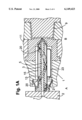
- FIG. 1 is a partial cross section through a plastic injection molding die according to the present invention
- FIG. 1A is a partial cross section through an alternate embodiment of the plastic injection molding die of FIG. 1.
- FIG. 2 is a diagram of the temperature profile along the nozzle
- FIG. 3 is a perspective representation of the nozzle body with guide means installed and casing indicated;
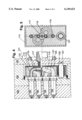
- FIG. 4 is a cross section through a hot channel injection molding die with four injection nozzles lying vertically above one another;
- FIG. 5 is a cross section along line II--II through the distribution block in FIG. 4;
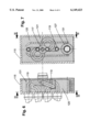
- FIG. 6 is a cross section through a further embodiment of the invention along line III--III in FIG. 7 with four injection nozzles lying one above the other;
- FIG. 7 is a cross section along line IV--IV in FIG. 6.
- a hot channel nozzle designated with reference numeral 1
- the entirety of a hot channel nozzle has a tube-shaped nozzle body 3 with a central boring which forms the injection channel 5 and is aligned at the entry side in region A with a boring 7 in the hot channel plate 2.
- the injection channel 5 ends in region B, but tapers there before the cavity 9.
- the cavity 9 is located in the so-called base plate 11, also called the insertion plate.
- the nozzle body 3 is enclosed over almost its entire length by a casing 13 forming a hollow space 15.
- Within the hollow space are contained two guide means 17 and 19 which embrace the nozzle body 3.
- the peripheries of the two guide means 17 and 19 preferably lie against the interior of the casing 13.
- the total hollow space 15 is filled with a fluid, for example with oil.
- the latter is poured in through a bore hole 21.
- Another heat-conducting liquid or a gas could be poured in as an alternative to oil.
- a heating element 23 is arranged below the casing 13 . This lies completely on the surface of the casing 13.
- FIG. 2 shows the profile of the temperature T over the entire length of the nozzle body 3 and further partial areas at both ends in the hot channel plate 2 and in the base plate 11.
- a conically shaped casing could also be used in order to support the heat transport appropriately.
- beads (20) can be applied to the casing 13, which project into the hollow space 15 and assume the function of the baffles 17 and 19. These embodiments are represented in FIG. 1A.
- the heat generated by the heating element 23 proceeds from below through the jacket of the casing 13 to the oil in the space 15. This is heated and rises upwardly on both sides from the deepest spot in the region area of the crest S. The rise does not, however, take place vertically, but the two baffles 17 and 19 cause the heated rising oil to be deflected to the ends of the nozzle body. In these regions A, B, the nozzle body 3 is strongly heated or cooled as a consequence of heat inflow and outflow in adjacent regions.
- the temperature T remains almost constant until near the end at the base plate side of the nozzle 3, and ranges even in a band of a few degrees Celsius. Only in the region of the transition to the cooled base plate 11 does the temperature fall below the mean value. It remains nonetheless within an optimal processing range for the plastic material. A temperature spike, which can lead to damaging the material, is successfully avoided.
- FIGS. 1, 2, and 3 depicts two baffles 17, 19. Obviously, with a longer nozzle, a modified baffle configuration could find application. Equally obvious would be such a configuration with a single baffle 17, in the event that the nozzle is very short.
- a hot channel injection molding die is visible, which includes three mold blocks, namely the base plate 103, the hot runner plate 105 and a cover plate 107.
- Four injection nozzles 109 are installed in the base plate 103, which lie vertically directly above one another.
- a discharge sleeve 117 is mounted in which the outlet opening for the liquified plastic material is situated, which for example can be conveyed to the hot channel injection molding die 101 by a screw conveyor and introduced into this.
- the hot runner plate 105 has a recess 113, in which a hollow body 115 is installed in the embodiments represented.
- a discharge sleeve 117 is mounted for introducing the liquid plastic mass. From this the liquid plastic is distributed to the injection nozzles 109 by distribution conduits 119.
- the distribution conduits 119 end in the side wall 121 of the hollow body 115 and are tightly connected with the latter, for example hard soldered, welded or the like.
- the tube-shaped distribution conduits 119 have curved regions 123 between the connection point A with the discharge sleeve 117 and their ends in the wall 121, the bending radius of which has the largest possible value permitted by the space relationship.
- a further heat source for example a heating cartridge 127
- the heating cartridge 127 lies protected in a tube 129, which is open on both ends and permits changing the heat cartridge 127 without having to open the hollow body 115.
- This is completely filled with a heat-conducting medium, for example a liquid, such as oil, or a gas.
- the medium surrounds the distribution conduits 119 situated in the hollow space 125, and the discharge sleeve 117 as well.
- the heat generated in the interior of the hollow body 115 by the heater below the distribution conduits 119 is transferred to the heat-conducting medium, and begins a circulation by convection and therewith uniform coverage of all surfaces of the distribution conduits 119 lying in the heat-conducting medium.
- the circulation of the medium effects a balanced heat transfer from the medium to the distribution conduits 119 and the plastic material conducted therein.
- a local overheating, for example in the region of the distribution tube 119 lying closest to the heater 127, is ruled out.
- a circulation can take place with a pump in very large molds (no illustration).
- baffles 131 are installed in the hollow space 125 of the hollow body 115 laterally of the distribution conduits 119.
- the baffles 131 conduct the medium heated by the heater 127 upward within a narrow channel 133 along the distribution conduits lying one above the other and allow the medium thereby cooled above, and for this reason specifically heavier, to sink downward outside the baffles 131, where it is warmed again at the heater 127.
- the looped-shaped segments of the distribution conduits 119 penetrate the baffles 131.
Landscapes
- Engineering & Computer Science (AREA)
- Manufacturing & Machinery (AREA)
- Mechanical Engineering (AREA)
- Moulds For Moulding Plastics Or The Like (AREA)
- Injection Moulding Of Plastics Or The Like (AREA)
- Nozzles (AREA)
- Slide Fasteners, Snap Fasteners, And Hook Fasteners (AREA)
- Coating By Spraying Or Casting (AREA)
- Infusion, Injection, And Reservoir Apparatuses (AREA)
Applications Claiming Priority (5)
| Application Number | Priority Date | Filing Date | Title |
|---|---|---|---|
| CH32196 | 1996-02-07 | ||
| CH321/96 | 1996-02-07 | ||
| CH2504/96 | 1996-10-14 | ||
| CH250496 | 1996-10-14 | ||
| PCT/CH1997/000036 WO1997028945A1 (de) | 1996-02-07 | 1997-02-05 | Heisskanal-spritzwerkzeug |
Publications (1)
| Publication Number | Publication Date |
|---|---|
| US6149423A true US6149423A (en) | 2000-11-21 |
Family
ID=25684218
Family Applications (1)
| Application Number | Title | Priority Date | Filing Date |
|---|---|---|---|
| US08/930,849 Expired - Lifetime US6149423A (en) | 1996-02-07 | 1997-02-05 | Hot channel injection moulding die |
Country Status (13)
| Country | Link |
|---|---|
| US (1) | US6149423A (de) |
| EP (1) | EP0820374B1 (de) |
| JP (1) | JPH11504286A (de) |
| AT (1) | ATE224283T1 (de) |
| AU (1) | AU1435797A (de) |
| CA (1) | CA2217022C (de) |
| CZ (1) | CZ298097A3 (de) |
| DE (1) | DE59708239D1 (de) |
| HU (1) | HUP9800758A3 (de) |
| IL (1) | IL121867A (de) |
| PL (1) | PL181842B1 (de) |
| SK (1) | SK134997A3 (de) |
| WO (1) | WO1997028945A1 (de) |
Cited By (12)
| Publication number | Priority date | Publication date | Assignee | Title |
|---|---|---|---|---|
| US20040191358A1 (en) * | 2003-03-31 | 2004-09-30 | Mold-Masters Limited | Cast hot runner manifold for injection molding apparatus |
| US20050288807A1 (en) * | 2004-06-24 | 2005-12-29 | Plastic Engineering & Technical Services, Inc. | Semi-automated computer-implemented method and system for designing manifold assemblies |
| US20100183763A1 (en) * | 2009-01-22 | 2010-07-22 | Mold-Masters (2007) Limited | Injection Molding Apparatus |
| US20110135781A1 (en) * | 2009-12-08 | 2011-06-09 | Husky Injection Molding Systems Ltd. | Mold-Tool System having Melt-Splitting Device Including Uninterrupted Melt Channels Extending From Inlet and Outlets |
| US8206146B2 (en) | 2009-12-08 | 2012-06-26 | Husky Injection Molding Systems Ltd. | Mold-tool system having a manifold body defining uninterrupted melt channels |
| CN103009574A (zh) * | 2012-11-20 | 2013-04-03 | 浙江千禧光塑料模具有限公司 | 一种易拆卸热嘴的热流道装置 |
| US8540507B2 (en) | 2009-12-08 | 2013-09-24 | Husky Injection Molding Systems, Ltd. | Mold tool system having manifold body including uninterrupted melt channels |
| US8545212B2 (en) | 2009-12-08 | 2013-10-01 | Husky Injetion Molding Systems Ltd. | Mold-tool system having melt splitting device including uninterrupted melt channels extending from inlet and outlets |
| US20130309342A1 (en) * | 2010-09-23 | 2013-11-21 | Husky Injection Molding Systems Ltd. | Mold-Tool Assembly Including Constant-Temperature Heater Assembly for Manifold Assembly |
| CN103770276A (zh) * | 2014-01-21 | 2014-05-07 | 杭州安费诺嘉力讯连接技术有限公司 | 一种应用在嵌件成型中的料带矫正型流道 |
| WO2015017741A1 (en) * | 2013-08-01 | 2015-02-05 | Husky Injection Molding Systems Ltd. | Injection-molding systems having hot-runner manifolds containing non-melt internal channels for providing operability enhancements |
| IT201800005633A1 (it) * | 2018-05-23 | 2019-11-23 | Distributore di gomma termoregolato per stampi a iniezione |
Families Citing this family (2)
| Publication number | Priority date | Publication date | Assignee | Title |
|---|---|---|---|---|
| US6468649B1 (en) | 1995-02-22 | 2002-10-22 | Scimed Life Systems, Inc. | Antimicrobial adhesion surface |
| DE102010020077A1 (de) * | 2010-05-10 | 2011-12-15 | Günther Heißkanaltechnik GmbH | Heißkanaldüse und Spritzgießwerkzeug mit einer Heißkanaldüse |
Citations (8)
| Publication number | Priority date | Publication date | Assignee | Title |
|---|---|---|---|---|
| GB243514A (en) * | 1924-11-17 | 1925-12-03 | Praecisionsgussfabrik Gebr Eck | Apparatus for melting non-metallic especially incombustible celluloid masses to be used in apparatus for casting under pressure |
| US2354363A (en) * | 1943-04-23 | 1944-07-25 | Arthur A Burry | Means for heating thermoplastic materials for molding |
| FR1188316A (fr) * | 1957-12-13 | 1959-09-22 | Fr Des Procedes Dykehouse Soc | Perfectionnements aux têtes chauffantes des machines à mouler par injection |
| US3790324A (en) * | 1972-06-14 | 1974-02-05 | Young Rubber Co | Extension runner system sprue arrangements for molding apparatus |
| GB1535164A (en) * | 1975-12-02 | 1978-12-06 | Rohm & Haas Ltd | Hot runner |
| GB2109296A (en) * | 1981-10-30 | 1983-06-02 | Shigeru Tsutsumi | Cooling injection mould gates |
| JPS60165462A (ja) * | 1984-02-09 | 1985-08-28 | Hitachi Cable Ltd | 加熱装置 |
| JPH06262650A (ja) * | 1993-02-04 | 1994-09-20 | Sadao Shimizu | 滑らかな曲線の樹脂通路を内蔵する射出成形機用マニーホールドの製造法 |
-
1997
- 1997-02-05 CZ CZ972980A patent/CZ298097A3/cs unknown
- 1997-02-05 WO PCT/CH1997/000036 patent/WO1997028945A1/de not_active Ceased
- 1997-02-05 DE DE59708239T patent/DE59708239D1/de not_active Expired - Lifetime
- 1997-02-05 AT AT97900928T patent/ATE224283T1/de not_active IP Right Cessation
- 1997-02-05 JP JP9528020A patent/JPH11504286A/ja not_active Ceased
- 1997-02-05 AU AU14357/97A patent/AU1435797A/en not_active Abandoned
- 1997-02-05 HU HU9800758A patent/HUP9800758A3/hu unknown
- 1997-02-05 EP EP97900928A patent/EP0820374B1/de not_active Expired - Lifetime
- 1997-02-05 PL PL97322493A patent/PL181842B1/pl not_active IP Right Cessation
- 1997-02-05 SK SK1349-97A patent/SK134997A3/sk unknown
- 1997-02-05 IL IL12186797A patent/IL121867A/xx not_active IP Right Cessation
- 1997-02-05 CA CA002217022A patent/CA2217022C/en not_active Expired - Lifetime
- 1997-02-05 US US08/930,849 patent/US6149423A/en not_active Expired - Lifetime
Patent Citations (8)
| Publication number | Priority date | Publication date | Assignee | Title |
|---|---|---|---|---|
| GB243514A (en) * | 1924-11-17 | 1925-12-03 | Praecisionsgussfabrik Gebr Eck | Apparatus for melting non-metallic especially incombustible celluloid masses to be used in apparatus for casting under pressure |
| US2354363A (en) * | 1943-04-23 | 1944-07-25 | Arthur A Burry | Means for heating thermoplastic materials for molding |
| FR1188316A (fr) * | 1957-12-13 | 1959-09-22 | Fr Des Procedes Dykehouse Soc | Perfectionnements aux têtes chauffantes des machines à mouler par injection |
| US3790324A (en) * | 1972-06-14 | 1974-02-05 | Young Rubber Co | Extension runner system sprue arrangements for molding apparatus |
| GB1535164A (en) * | 1975-12-02 | 1978-12-06 | Rohm & Haas Ltd | Hot runner |
| GB2109296A (en) * | 1981-10-30 | 1983-06-02 | Shigeru Tsutsumi | Cooling injection mould gates |
| JPS60165462A (ja) * | 1984-02-09 | 1985-08-28 | Hitachi Cable Ltd | 加熱装置 |
| JPH06262650A (ja) * | 1993-02-04 | 1994-09-20 | Sadao Shimizu | 滑らかな曲線の樹脂通路を内蔵する射出成形機用マニーホールドの製造法 |
Cited By (22)
| Publication number | Priority date | Publication date | Assignee | Title |
|---|---|---|---|---|
| US7326049B2 (en) | 2003-03-31 | 2008-02-05 | Mold-Masters (2007) Limited | Cast hot runner manifold for injection molding apparatus |
| US20040191358A1 (en) * | 2003-03-31 | 2004-09-30 | Mold-Masters Limited | Cast hot runner manifold for injection molding apparatus |
| US20050288807A1 (en) * | 2004-06-24 | 2005-12-29 | Plastic Engineering & Technical Services, Inc. | Semi-automated computer-implemented method and system for designing manifold assemblies |
| US8282386B2 (en) | 2009-01-22 | 2012-10-09 | Mold-Masters (2007) Limited | Injection molding apparatus |
| US20100183763A1 (en) * | 2009-01-22 | 2010-07-22 | Mold-Masters (2007) Limited | Injection Molding Apparatus |
| US8545212B2 (en) | 2009-12-08 | 2013-10-01 | Husky Injetion Molding Systems Ltd. | Mold-tool system having melt splitting device including uninterrupted melt channels extending from inlet and outlets |
| US8167609B2 (en) | 2009-12-08 | 2012-05-01 | Husky Injection Molding Systems Ltd. | Mold-tool system having a melt-splitting device including uninterrupted melt channels extending from a melt inlet to a plurality of melt outlets |
| US8206146B2 (en) | 2009-12-08 | 2012-06-26 | Husky Injection Molding Systems Ltd. | Mold-tool system having a manifold body defining uninterrupted melt channels |
| US8540507B2 (en) | 2009-12-08 | 2013-09-24 | Husky Injection Molding Systems, Ltd. | Mold tool system having manifold body including uninterrupted melt channels |
| US20110135781A1 (en) * | 2009-12-08 | 2011-06-09 | Husky Injection Molding Systems Ltd. | Mold-Tool System having Melt-Splitting Device Including Uninterrupted Melt Channels Extending From Inlet and Outlets |
| US20130309342A1 (en) * | 2010-09-23 | 2013-11-21 | Husky Injection Molding Systems Ltd. | Mold-Tool Assembly Including Constant-Temperature Heater Assembly for Manifold Assembly |
| CN103009574B (zh) * | 2012-11-20 | 2015-04-01 | 浙江千禧光塑料模具有限公司 | 一种易拆卸热嘴的热流道装置 |
| CN103009574A (zh) * | 2012-11-20 | 2013-04-03 | 浙江千禧光塑料模具有限公司 | 一种易拆卸热嘴的热流道装置 |
| WO2015017741A1 (en) * | 2013-08-01 | 2015-02-05 | Husky Injection Molding Systems Ltd. | Injection-molding systems having hot-runner manifolds containing non-melt internal channels for providing operability enhancements |
| CN105377526A (zh) * | 2013-08-01 | 2016-03-02 | 赫斯基注塑系统有限公司 | 具有含非熔体内部通道的热流道歧管以增强操作性的注塑系统 |
| US10766176B2 (en) | 2013-08-01 | 2020-09-08 | Husky Injection Molding Systems Ltd. | Injection-molding systems having hot-runner manifolds containing non-melt internal channels for providing operability enhancements |
| CN103770276A (zh) * | 2014-01-21 | 2014-05-07 | 杭州安费诺嘉力讯连接技术有限公司 | 一种应用在嵌件成型中的料带矫正型流道 |
| CN103770276B (zh) * | 2014-01-21 | 2015-12-02 | 杭州安费诺嘉力讯连接技术有限公司 | 一种应用在嵌件成型中的料带矫正型流道 |
| IT201800005633A1 (it) * | 2018-05-23 | 2019-11-23 | Distributore di gomma termoregolato per stampi a iniezione | |
| WO2019224621A1 (en) * | 2018-05-23 | 2019-11-28 | Ncn Technology S.R.L. | Thermoregulated rubber distributor for injection molds |
| EA038778B1 (ru) * | 2018-05-23 | 2021-10-19 | Нсн Технолоджи С.Р.Л. | Терморегулируемый распределитель резины для литьевых форм |
| US11685091B2 (en) | 2018-05-23 | 2023-06-27 | Ncn Technology S.R.L. | Thermoregulated rubber distributor for injection molds |
Also Published As
| Publication number | Publication date |
|---|---|
| SK134997A3 (en) | 1998-02-04 |
| WO1997028945A1 (de) | 1997-08-14 |
| HUP9800758A3 (en) | 1999-06-28 |
| EP0820374B1 (de) | 2002-09-18 |
| DE59708239D1 (de) | 2002-10-24 |
| PL322493A1 (en) | 1998-02-02 |
| CA2217022C (en) | 2002-08-20 |
| JPH11504286A (ja) | 1999-04-20 |
| EP0820374A1 (de) | 1998-01-28 |
| ATE224283T1 (de) | 2002-10-15 |
| AU1435797A (en) | 1997-08-28 |
| HUP9800758A2 (hu) | 1998-07-28 |
| PL181842B1 (pl) | 2001-09-28 |
| IL121867A (en) | 2001-01-28 |
| IL121867A0 (en) | 1998-02-22 |
| CA2217022A1 (en) | 1997-08-14 |
| CZ298097A3 (cs) | 1998-02-18 |
Similar Documents
| Publication | Publication Date | Title |
|---|---|---|
| CA2217022C (en) | Hot channel injection moulding die | |
| EP0195111A2 (de) | Kühlvorrichtung für einen Formhohlraum | |
| US4395222A (en) | Injection molding apparatus | |
| US6619948B2 (en) | Hot runner nozzle | |
| US4451224A (en) | Mold device for making plastic articles from resin | |
| CN1997499B (zh) | 模制装置 | |
| CN101811338B (zh) | 一种可实现急冷急热的模具 | |
| AU727837B2 (en) | On-demand fast cycle mold | |
| US4563149A (en) | Injection molding apparatus | |
| CN107175799A (zh) | 热流道系统和相关的喷嘴加热装置 | |
| JPS6036118A (ja) | 高温マニホルド装置 | |
| CN107000285A (zh) | 用于用塑料制造注模构件的注模喷嘴 | |
| KR100472201B1 (ko) | 분리식으로 구성된 사출기 금형용 핫런너 매니폴드와 그제작방법 | |
| US4648833A (en) | Hot nozzle for runnerless mold | |
| US5587188A (en) | Multitip hot runner system | |
| WO2001014119A1 (en) | Core fluid velocity inducer | |
| CN108885278A (zh) | 用于镜片制造期间的保形冷却的系统和方法 | |
| US9446543B2 (en) | Injection mould with hot runner manifold | |
| EP1584442B1 (de) | Spritzgiessdüsenkörper mit geheizten und ungeheizten Düsenkörperteilen | |
| KR100625348B1 (ko) | 온도센서를 장착한 웰드라인 방지 금형 | |
| JPS63256415A (ja) | プラスチツク射出成形機のための加熱通路装置 | |
| KR100625349B1 (ko) | 단열재를 탑재한 웰드라인 방지 금형 | |
| JP3369962B2 (ja) | ガスアシスト成形法による樹脂製品の成形方法及び成形装置 | |
| EP0967062A1 (de) | Form und Giessverfahren | |
| US8540507B2 (en) | Mold tool system having manifold body including uninterrupted melt channels |
Legal Events
| Date | Code | Title | Description |
|---|---|---|---|
| AS | Assignment |
Owner name: SCHOTTLI AG, SWITZERLAND Free format text: ASSIGNMENT OF ASSIGNORS INTEREST;ASSIGNOR:MANZ, WILLI;REEL/FRAME:008830/0465 Effective date: 19970911 |
|
| STCF | Information on status: patent grant |
Free format text: PATENTED CASE |
|
| FPAY | Fee payment |
Year of fee payment: 4 |
|
| FPAY | Fee payment |
Year of fee payment: 8 |
|
| FPAY | Fee payment |
Year of fee payment: 12 |