US6151045A - Surface modified nozzle plate - Google Patents
Surface modified nozzle plate Download PDFInfo
- Publication number
- US6151045A US6151045A US09/235,578 US23557899A US6151045A US 6151045 A US6151045 A US 6151045A US 23557899 A US23557899 A US 23557899A US 6151045 A US6151045 A US 6151045A
- Authority
- US
- United States
- Prior art keywords
- nozzle
- nozzle plate
- polydialkylsiloxane
- polyimide
- arrays
- Prior art date
- Legal status (The legal status is an assumption and is not a legal conclusion. Google has not performed a legal analysis and makes no representation as to the accuracy of the status listed.)
- Expired - Lifetime
Links
Images
Classifications
-
- B—PERFORMING OPERATIONS; TRANSPORTING
- B41—PRINTING; LINING MACHINES; TYPEWRITERS; STAMPS
- B41J—TYPEWRITERS; SELECTIVE PRINTING MECHANISMS, i.e. MECHANISMS PRINTING OTHERWISE THAN FROM A FORME; CORRECTION OF TYPOGRAPHICAL ERRORS
- B41J2/00—Typewriters or selective printing mechanisms characterised by the printing or marking process for which they are designed
- B41J2/005—Typewriters or selective printing mechanisms characterised by the printing or marking process for which they are designed characterised by bringing liquid or particles selectively into contact with a printing material
- B41J2/01—Ink jet
- B41J2/135—Nozzles
- B41J2/16—Production of nozzles
- B41J2/1606—Coating the nozzle area or the ink chamber
-
- B—PERFORMING OPERATIONS; TRANSPORTING
- B41—PRINTING; LINING MACHINES; TYPEWRITERS; STAMPS
- B41J—TYPEWRITERS; SELECTIVE PRINTING MECHANISMS, i.e. MECHANISMS PRINTING OTHERWISE THAN FROM A FORME; CORRECTION OF TYPOGRAPHICAL ERRORS
- B41J2/00—Typewriters or selective printing mechanisms characterised by the printing or marking process for which they are designed
- B41J2/005—Typewriters or selective printing mechanisms characterised by the printing or marking process for which they are designed characterised by bringing liquid or particles selectively into contact with a printing material
- B41J2/01—Ink jet
- B41J2/135—Nozzles
- B41J2/14—Structure thereof only for on-demand ink jet heads
- B41J2/1433—Structure of nozzle plates
-
- B—PERFORMING OPERATIONS; TRANSPORTING
- B41—PRINTING; LINING MACHINES; TYPEWRITERS; STAMPS
- B41J—TYPEWRITERS; SELECTIVE PRINTING MECHANISMS, i.e. MECHANISMS PRINTING OTHERWISE THAN FROM A FORME; CORRECTION OF TYPOGRAPHICAL ERRORS
- B41J2/00—Typewriters or selective printing mechanisms characterised by the printing or marking process for which they are designed
- B41J2/005—Typewriters or selective printing mechanisms characterised by the printing or marking process for which they are designed characterised by bringing liquid or particles selectively into contact with a printing material
- B41J2/01—Ink jet
- B41J2/135—Nozzles
- B41J2/14—Structure thereof only for on-demand ink jet heads
- B41J2002/14491—Electrical connection
Definitions
- the invention relates to ink-jet printers and, in particular, surface modified nozzle plates for printheads which exhibit modified wettability characteristics.
- Ink jet printer technology continues to improve to provide faster printers which produce higher quality print.
- printhead materials, designs and manufacturing procedures continue to change and evolve.
- the nozzle plates contain smaller, more closely spaced nozzle holes and increased numbers of nozzle holes per nozzle plate.
- ink tends to accumulate on the nozzle plate surface adjacent the nozzle holes.
- the accumulated ink can, over time, partially block and cause misdirection of ink droplets ejected from the nozzle plate or, in a severe case, totally block ink ejection from the affected nozzle hole.
- An excess accumulation of ink on the nozzle plate adjacent a nozzle hole during firing of a nozzle is often referred to in the art as "flooding" since the ink may actually accumulate to the point that it covers the nozzle holes.
- Another accumulation of ink on the nozzle plate is the result of ink pooling.
- “Pooling” is defined as the accumulation of ink on the nozzle plate when a "tail" of ink forms as the ink droplet is ejected and the ink tail breaks away from the main droplet and deposits back on the nozzle plate. Pooling of ink does not necessarily occur only adjacent the nozzle holes and may occur anywhere on the nozzle plate.
- ink accumulation on a nozzle plate of a multi-color printhead whether from flooding or pooling may result in ink color mixing.
- ink color mixing the ink droplets ejected from affected nozzle holes may not provide the intended color dots thereby reducing print quality.
- nozzle holes and their associated ink ejection heaters become smaller and the distance between adjacent nozzle holes is reduced to provide higher quality, faster printing, the effects of ink accumulation or flooding of the nozzle plates becomes a more important factor in the operation of the printer.
- coatings which have been applied to components of the printhead for various purposes have been observed to result in covering the nozzle holes and thereby interfere with the operation of the printhead.
- coatings are typically applied during one or more steps in the manufacturing process and include adhesives, epoxies, silicones, polyurethanes and the like which are applied to protect electrical components of the printhead from corrosion caused by the ink.
- Another object of the invention is to provide a nozzle plate having reduced ink flooding and pooling tendencies.
- a further object of the invention is to provide a method for making a nozzle plate for an ink jet printer.
- Another object of the invention is to provide a coated nozzle plate which avoids disadvantages of conventionally coated nozzle plates.
- Still another object of the invention is to provide a nozzle plate having a substantially durable surface-energy modifying coating.
- Another object of the invention is to provide a coating technique for applying a surface-energy modifying coating to selected areas of a nozzle plate.
- Another object of the invention is to provide a nozzle plate having an ink repellent coating in a pattern which substantially reduces ink flooding, pooling and ink color mixing.
- the invention provides a nozzle plate for an ink jet printer including a polyimide nozzle plate having an exposed surface wherein at least a portion of the exposed surface contains a coating or layer derived from a polydialkylsiloxane having at least one reactive end group and having a molecular weight ranging from about 500 to about 40,000 number average molecular weight.
- the invention provides a method for modifying surface wettability of a polymeric nozzle plate for an ink jet printer.
- the method includes applying polydialkylsiloxane having at least one reactive end group and having a molecular weight ranging from about 500 to about 40,000 number average molecular weight to at least a portion of an exposed surface of a polyimide nozzle plate, and heating the nozzle plate and polydialkylsiloxane for a period of time under conditions sufficient to provide an exposed surface-energy modifying coating or layer having a thickness ranging from about 500 ⁇ ngstroms to less than about 0.1 micron.
- An advantage of the coating and method of the invention is that an effective coating may be applied to a nozzle plate which may be cured along with the adhesives used to assemble the nozzle plate to the chip or semiconductor substrate.
- the polydialkylsiloxane is sufficiently reactive with the nozzle plate material at the adhesive curing temperatures to form a durable bond therewith without the need for an intermediate coating between the polydialkylsiloxane and the nozzle plate.
- only a relatively small amount of polydialkylsiloxane is required to achieve a desirable reduction in surface-energy properties of the nozzle. This results in a significantly reduced coating thickness as compared to prior coatings, thus avoiding problems associated with relatively thick coatings.
- the polydialkylsiloxane coating may be readily applied to a nozzle plate material by a variety of coating techniques. Selective application of the surface-energy modification material to portions of the nozzle plate adjacent the nozzle holes may be used to direct ink to ink recovery areas of the nozzle plate, to prevent ink color mixing between different color inks or to prevent flow of coating or adhesive materials over the nozzle holes during one or more printhead manufacturing steps.
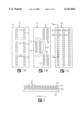
- FIGS. 1A, 1B and 1C are plan top views of nozzle plates containing a surface-energy modifying coating according to the invention.
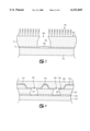
- FIG. 2 is a cross-sectional view, not to scale of a portion of a nozzle plate containing a surface-energy modifying coating according to the invention
- FIG. 3 is an enlarged cross-sectional view through one nozzle hole of a nozzle plate containing a coating according to the invention
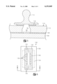
- FIG. 4 is an enlarged cross-sectional view of one method for applying a surface-energy modifying coating according to the invention
- FIG. 5 is an enlarged cross-sectional view of another method for applying a surface-energy modifying coating according to the invention.
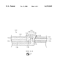
- FIG. 6 is a top plan view of a nozzle plate attached to a silicon substrate and a flex circuit showing selected surface-energy modified areas on the nozzle plate surface;
- FIG. 7 is an enlarged cross-sectional view through a portion of the printhead assembly of FIG. 6.
- a nozzle plate for an ink jet printer which includes a surface-energy modifying compound on at least a portion of one exposed surface of the nozzle plate.
- the nozzle plates are typically polymeric materials, most preferably polyimide.
- Polyimide is relatively hydrophobic and has an untreated surface-energy of about 45 dynes.
- a lower surface-energy, preferably lower than about 40 dynes and most preferably lower than about 30 dynes is desirable in order to reduce flooding and flow of coating materials over the nozzle holes.
- the exposed surface of the polyimide may be treated or coated with a suitable material to provide a layer having the desired wettability properties.
- a suitable material to provide a layer having the desired wettability properties.
- the polyimide may be reacted with or etched under certain conditions to provide reactive sites for chemical modification of the surface properties thereof.
- the polyimide may be exposed to a strong base such as potassium hydroxide or sodium hydroxide for a sufficient period of time at an elevated temperature, and then rinsed and neutralized with a dilute acid.
- carboxyl groups are formed at the surface of the polyimide.
- the carboxyl groups may be reacted with epoxies, hydrazines, alcohols and the like as described more fully in U.S. Pat. No. 5,133,840 to Buchwalter et al., the entire disclosure of which is incorporated by reference as if fully set forth herein.
- a particularly preferred method for lowering the surface-energy of the polyimide nozzle plate is to contact the surface with a polymeric compound having at least one terminal group which is reactive with the polyimide and then causing the end group to react with the polyimide under conditions sufficient to form a relatively strong chemical bond between the polyimide and the end group of the polymer.
- the end group of the polymer is preferably a basic end group, most preferably an amine end group which is basic enough at an elevated temperature to open the imide ring of the polyimide to form an amide bond therewith.
- polyimide nozzle plate it is preferred to react the polyimide nozzle plate with an amine terminated polysiloxane, more preferably an aminoalkyl terminated polydialkylsiloxane and most preferably an aminopropyl terminated polydimethylsiloxane (ATPDMS) of the formula ##STR1## wherein n is an integer ranging from about 100 to about 500.
- a particularly preferred siloxane compound of the foregoing formula has a number average molecular weight ranging from about 500 to about 40,000, and is available from Gelest, Inc. of Tullytown, Pa. under the trade designation DMS-A32.
- the ATPDMS is reacted at the adhesive cure temperature used to bond the nozzle plate to a semiconductor chip.
- a preferred temperature for causing reaction between the ATPDMS and the polyimide is from about 135° to about 200° C., most preferably from about 140° to about 190° C. While the reaction between the ATPDMS and polyimide is relatively rapid at elevated temperatures, in order to completely cure the adhesive at the same time, it is preferred to maintain the temperature for at least about 20 minutes, preferably from about 30 to about 50 minutes or more.
- a relatively thin layer of the APDMS provides a substantial decrease in the surface-energy of the polyimide.
- the untreated polyimide may have a surface-energy of about 45 dynes
- treatment of the surface of the polyimide under the conditions described herein has been found to lower the surface-energy to less than about 30 dynes, preferably less than about 25 dynes and most preferably to a range of from about 15 to about 20 dynes.
- ATPDMS reacted under the conditions described above forms a monolayer of polydimethylsiloxane (PDMS) on the surface of the polyimide which is covalently bound to the polyimide through an amide linkage.
- the coating thickness may range from about 500 ⁇ ngstroms to less than about 0.1 micron in total thickness, and has been observed to be durable for the use of print head applications.
- a polyimide material which may be used as a nozzle includes materials available from DuPont Corporation of Wilmington, Del. under the trade name PYRALUX and from Rogers Corporation of Chandler, Ariz. under the trade name R-FLEX 1100. It is particularly preferred to use a polyimide material which contains an adhesive layer on one surface for attaching the polyimide nozzle plate to a semiconductor chip.
- the flow features including the nozzle holes and ink chambers are formed in the polyimide using laser ablation techniques. Once the flow features and nozzles are formed, the nozzle plate is tacked to the semiconductor chip using heat and pressure. Prior to curing the adhesive between the polyimide and the chip, the ATPDMS is applied to the exposed surface of the nozzle plate in the desired locations.
- FIGS. 1A-1C illustrate coating designs which provide desirable wettable and non-wettable nozzle plate surfaces.
- FIG. 1A is a plan view from the exposed surface of a nozzle plate 10 containing coated areas 12, 14 and 16 which are adjacent nozzle hole arrays 18, 20 and 22, respectively.
- Nozzle hole arrays 18, 20 and 22 may be used for multicolor application of ink to a print media with each array being a separate color or the arrays may be used together to apply a single color ink to a print media. Regardless of whether the nozzle plate is used for a single color printing or multi-color color printing, only the areas immediately adjacent the nozzle hole arrays 18, 20 and 22 contain a monolayer of PDMS while more remote areas such as areas 24 are not treated with the ATPDMS.
- FIG. 1B illustrates another nozzle hole array design for a single or multi-color ink jet printer nozzle plate 30 according to the invention.
- Each of the nozzle hole arrays 32, 34 and 36 is surrounded by the PDMS coatings 38, 40 and 42 respectively in order to provide a surface-energy adjacent the nozzle hole arrays which is lower than the surface-energy of the untreated areas.
- An additional coated area 44 remote from adjacent the nozzle hole arrays may be provided to further isolate nozzle hole arrays 32 and 36 from array 34 for improved printhead operation.
- FIG. 1C Yet another treated nozzle plate 50 is shown in FIG. 1C.
- the plate 50 includes nozzle arrays 52, 54 and 56.
- each of the nozzle hole arrays may be used to apply a single color or a different color ink to a print media.
- Each of the arrays 52-56 is surrounded by a treated area, 58, 60 and 62 respectively which effectively reduces the surface-energy of the nozzle plate in the areas surrounding or adjacent the nozzle holes.
- the annular treated area around the nozzle holes preferably ranges from about 5 to about 100 ⁇ m wide.
- a preferred annular treated area immediately adjacent each nozzle hole is about 50 ⁇ m wide.
- the annular width of the treated area 44 is about 50 to about 300 ⁇ m wide.
- FIG. 2 is a partial cross sectional view through the nozzle plate 50 and silicon substrate 64 along line A--A of FIG. 1C which shows the relationship of the treated area 58 to the nozzle hole array 52.
- the nozzle plate 50 is preferably attached to the silicon substrate 64 using adhesive 66.
- FIG. 3 is an enlarged cross-sectional view, not to scale of one nozzle hole 68 of the nozzle hole array 52 of FIG. 1C.
- the nozzle hole 68 and ink chamber 70 are formed in the polyimide material 72 and adhesive layer 74 as by laser ablating the polyimide.
- the adhesive layer 74 is preferably a B-stageable thermal cure resin, including but not limited to, phenolic resins, resorcinol resins, epoxy resins, ethylene-urea resins, furane resins, polyurethane resins, silicone resins and the like, which are used to fixedly attach the polyimide material 72 to a silicon substrate 76.
- a monolayer 78 of ATPDMS is applied and cured so that PDMS is covalently bound to the substrate by reaction between a terminal aminopropyl group of the ATPDMS and the polyimide material.
- the treated area containing monolayer 78 effectively repels ink ejected through nozzle hole 68 by means of heater 80 so that it doesn't accumulate on the surface 82 of the polyimide 72 in the area immediately adjacent the nozzle hole 68. Because the PDMS is bound to the polyimide surface 82, the treated area is essentially durable and resists removal during printhead cleaning operations.
- the ATPDMS treatment has been demonstrated to remain effective after more than about 500 to about 5000 printhead cleaning cycles.
- a subjective scale of 0 to 7 is used with 0 being no flooding or pooling and 7 being significant accumulation of ink on the nozzle plate.
- a lighted microscope is used to observe the ink accumulation around the nozzle holes during firing of the nozzles into space.
- the pooling potential of a nozzle plate or coating is also observed with the use a lighted microscope after terminating the operation of the printhead.
- the printhead is used to print images on a print media during the printhead operation.
- Untreated nozzle plates have flooding rates of 4-5 whereas the flooding rate of the polyimide nozzle plate treated with ATPDMS according to the invention is about 0 to about 1.
- the ATPDMS may be applied to the exposed surface of the nozzle plate by a variety of techniques including spraying, dipping, spin coating, brushing, and the like.
- a silicon rubber pad or roller is impregnated with ATPDMS and the pad or roller is contacted with the exposed surface of the nozzle plate in order to transfer a layer of ATPDMS to the nozzle plate surface.
- Contact pressure which may be required to transfer a sufficient amount of the ATPDMS to the nozzle plate may range from about 10 pounds per square inch to less than about 100 pounds per square inch.
- FIG. 4 shows a preferred method for applying the ATPDMS to the surface 90 of a polyimide nozzle plate 92.
- a mask 94 containing apertures or openings of the desired coating design as described with reference to FIGS. 1A-1C is aligned with the nozzle holes 96 adjacent the surface 90 of the nozzle plate 92.
- a silicon rubber roller or pad 98 impregnated with ATPDMS is pressed against the mask 94 so that selected portions of the roller or pad 98 deposit a thin coating of ATPDMS on the surface 90 of the nozzle plate 92 through the openings or apertures in the mask 94.
- the coating thickness of the ATPDMS ranges from about 500 ⁇ to about 0.1 ⁇ m.
- a curing cycle for adhesive 100 to bond the nozzle plate 92 to the silicon chip 102 is conducted.
- the curing cycle for adhesive 100 is preferably accomplished at a temperature in the range of from about 150° to about 200° C. for a period of time ranging from about 20 to about 50 minutes or more.
- This curing cycle is believed to cause a reaction between the ATPDMS so that a monolayer of PDMS forms on the surface 90 of the nozzle plate 92.
- the normal wiping of the printhead during a printing operation removes any excess or unreacted ATPDMS from the surface 90 of the nozzle plate. Accordingly, a cleaning step after curing the nozzle plate adhesive is generally not necessary to obtain the treated nozzle plates according to the invention.
- FIG. 5 illustrates another method for applying the ATPDMS to selected areas of a surface 110 of a nozzle plate 112.
- a pad or roller 114 having impregnated silicon rubber application pads 116 of the desired coating design is pressed to the surface 110 of the nozzle plate 112 in the absence of a mask. Only the impregnated pads 116 contact the nozzle plate transferring an ATPDMS coating to the nozzle plate surface 110 in accordance with the pad design. Curing of the adhesive 100 and bonding of the coating to the nozzle plate proceeds as described above with reference to FIG. 4.
- these areas of the nozzle plate may contain channels or ink drain holes to return the ink to the ink supply or to an ink containment structure.
- the drain holes may be located between the nozzle holes above the ink via region or ink feed region on the semiconductor chip or between the nozzle holes and electrical contact pads adjacent the edge of the semiconductor chip.
- a wiper may be used in combination with the drain holes to remove excess ink in the area of the drain holes.
- FIGS. 6 and 7 illustrate a printhead 120 for an ink jet printer which includes a nozzle plate 122 attached to a semiconductor silicon chip 124 and a TAB circuit, flex circuit or printed circuit board 126 containing electrical traces 128 for electrically connecting ink energizing elements on the chip 124 to a printer for selective ejection of ink from nozzle holes 130.
- Electrical connections are typically made by attaching wires or traces 134 from contact pads 136 on the electrical traces 128 to contact pads 138 on the silicon chip 124 through openings or windows 132 in the nozzle plate 122, adhesive layers 140 and 142 and flex circuit material 126.
- an elastomeric encapsulate material 144 is applied adjacent windows 132 to protect the wires 134 and connections to the contact pads 136 and 138.
- the layer of elastomeric material is preferably no thicker than about 10 mils.
- Suitable encapsulate materials include silicon polymer coatings having a coefficient of thermal expansion greater than or equal to that of the wire 134 as well as silicone, polyurethane, and urethane acrylate coatings.
- areas of low surface-energy 146 are provided around the nozzle holes 130.
- the low surface-energy areas 146 are provided according to the methods described above by applying the ATPDMS to the selected areas of the nozzle plate 122.
- a high surface-energy coating may be applied to the nozzle plate after curing the low surface-energy coating.
- Suitable high surface-energy coatings include amine terminated polar compounds such as 3-amino-1,2-propanediol, 2-amino-5-nitrobenzene-sulfonic acid, aminopropylsulfonic acid sodium salt, sodium salt dihydrate and other amine terminated organic compounds such as, but not limited to alcohols, carboxylic acids and salt hydrates.
- These compounds may be applied using masking techniques or pads or rollers having the desired coating design, or by spraying, spin coating, dipping, or brushing the compound onto the surface of the nozzle plate after curing the low surface-energy coating. Because of the presence of the low surface-energy coating, the high surface-energy coating will only adhere to those areas of the nozzle plate which do not contain the PDMS material.
- a 2 wt. % aminopropylsulfonic acid sodium salt in gamma butyrol lactone and 5.6 wt. % water is spin coated onto the nozzle plate assembly after curing the adhesive and treating the nozzle plate with ATPDMS.
- the solution may be spun coated onto the assembly at about 1500 rpm for 2 minutes after presoaking the assembly with the solution for about 30 seconds.
- the coated nozzle plate is then cured at a temperature of from about 130° to about 155° C. for about 90 minutes or more. Excess and/or unreacted compound may be removed from the assembly by washing the assembly with deionized water.
Landscapes
- Engineering & Computer Science (AREA)
- Manufacturing & Machinery (AREA)
- Particle Formation And Scattering Control In Inkjet Printers (AREA)
- Adhesives Or Adhesive Processes (AREA)
Priority Applications (4)
| Application Number | Priority Date | Filing Date | Title |
|---|---|---|---|
| US09/235,578 US6151045A (en) | 1999-01-22 | 1999-01-22 | Surface modified nozzle plate |
| PCT/US1999/028864 WO2000043207A2 (en) | 1999-01-22 | 1999-12-06 | Surface modified nozzle plate |
| EP99960656A EP1156929A4 (de) | 1999-01-22 | 1999-12-06 | Düsenplatte mit modifizierter oberfläche |
| AU17511/00A AU1751100A (en) | 1999-01-22 | 1999-12-06 | Surface modified nozzle plate |
Applications Claiming Priority (1)
| Application Number | Priority Date | Filing Date | Title |
|---|---|---|---|
| US09/235,578 US6151045A (en) | 1999-01-22 | 1999-01-22 | Surface modified nozzle plate |
Publications (1)
| Publication Number | Publication Date |
|---|---|
| US6151045A true US6151045A (en) | 2000-11-21 |
Family
ID=22886086
Family Applications (1)
| Application Number | Title | Priority Date | Filing Date |
|---|---|---|---|
| US09/235,578 Expired - Lifetime US6151045A (en) | 1999-01-22 | 1999-01-22 | Surface modified nozzle plate |
Country Status (4)
| Country | Link |
|---|---|
| US (1) | US6151045A (de) |
| EP (1) | EP1156929A4 (de) |
| AU (1) | AU1751100A (de) |
| WO (1) | WO2000043207A2 (de) |
Cited By (23)
| Publication number | Priority date | Publication date | Assignee | Title |
|---|---|---|---|---|
| US6341842B1 (en) | 2000-05-03 | 2002-01-29 | Lexmark International, Inc. | Surface modified nozzle plate |
| US6664200B1 (en) * | 2000-04-28 | 2003-12-16 | Motorola Inc | Method of manufacturing a semiconductor component and polyimide etchant therefor |
| US20050245634A1 (en) * | 2004-04-29 | 2005-11-03 | Soutar Andrew M | UV curable coating composition |
| US20050245633A1 (en) * | 2004-04-29 | 2005-11-03 | Soutar Andrew M | UV curable coating composition |
| US20070040870A1 (en) * | 2005-08-16 | 2007-02-22 | Chun-Fu Lu | Nozzle plate |
| US20070263043A1 (en) * | 2006-05-10 | 2007-11-15 | Bruce Bradford | Industrial ink jet print head system |
| US20090185003A1 (en) * | 2008-01-23 | 2009-07-23 | Craig Michael Bertelsen | Hydrophobic nozzle plate structures for micro-fluid ejection heads |
| US20100045740A1 (en) * | 2008-08-19 | 2010-02-25 | Xerox Corporation | Fluid dispensing subassembly with compliant aperture plate |
| US20100156997A1 (en) * | 2008-12-18 | 2010-06-24 | Palo Alto Research Center Incorporated | Drop generating apparatus |
| US20100156988A1 (en) * | 2008-12-19 | 2010-06-24 | Canon Kabushiki Kaisha | Liquid ejection head and printing apparatus |
| US20100188465A1 (en) * | 2007-08-31 | 2010-07-29 | Canon Kabushiki Kaisha | Ink jet print head |
| US20110018937A1 (en) * | 2009-07-24 | 2011-01-27 | Silverbrook Research Pty Ltd | Printhead having ink ejection face complementing ink or other features of printhead |
| US20110018936A1 (en) * | 2009-07-24 | 2011-01-27 | Silverbrook Research Pty Ltd | Printhead having polymer incorporating nanoparticles coated on ink ejection face |
| TWI476113B (zh) * | 2009-07-24 | 2015-03-11 | Memjet Technology Ltd | 噴墨面上塗有含奈米粒子之聚合物的列印頭 |
| US20170157940A1 (en) * | 2011-03-31 | 2017-06-08 | Hewlett-Packard Development Company, L.P. | Printhead assembly |
| CN108136784A (zh) * | 2015-10-15 | 2018-06-08 | 惠普发展公司,有限责任合伙企业 | 印刷头中的维护结构 |
| WO2018186159A1 (ja) * | 2017-04-05 | 2018-10-11 | コニカミノルタ株式会社 | 液体吐出装置 |
| JP2020037234A (ja) * | 2018-09-05 | 2020-03-12 | キヤノン株式会社 | 液体吐出ヘッドとその製造方法 |
| WO2020170351A1 (ja) * | 2019-02-20 | 2020-08-27 | コニカミノルタ株式会社 | インクジェットヘッド、インクジェット画像形成装置、ノズルプレートの製造方法、およびインクジェットヘッドの製造方法 |
| JP2020196191A (ja) * | 2019-06-03 | 2020-12-10 | セイコーエプソン株式会社 | ヘッドユニットおよび液体吐出装置 |
| US11691423B2 (en) | 2019-07-30 | 2023-07-04 | Hewlett-Packard Development Company, L.P. | Uniform print head surface coating |
| US12097711B2 (en) | 2020-04-14 | 2024-09-24 | Hewlett-Packard Development Company, L.P. | Fluid-ejection die with stamped nanoceramic layer |
| US12600130B2 (en) | 2023-08-22 | 2026-04-14 | Brady Worldwide, Inc. | Ejection head nozzle flooding control |
Families Citing this family (3)
| Publication number | Priority date | Publication date | Assignee | Title |
|---|---|---|---|---|
| US7605009B2 (en) | 2007-03-12 | 2009-10-20 | Silverbrook Research Pty Ltd | Method of fabrication MEMS integrated circuits |
| CN101610909B (zh) * | 2007-03-12 | 2010-12-29 | 西尔弗布鲁克研究股份有限公司 | 制造具有疏水喷墨面的打印头的方法以及打印头 |
| JP2009132140A (ja) * | 2007-11-05 | 2009-06-18 | Seiko Epson Corp | 液滴吐出ヘッドおよび液滴吐出装置 |
Citations (11)
| Publication number | Priority date | Publication date | Assignee | Title |
|---|---|---|---|---|
| US3361589A (en) * | 1964-10-05 | 1968-01-02 | Du Pont | Process for treating polyimide surface with basic compounds, and polyimide surface having thin layer of polyamide acid |
| US4542389A (en) * | 1982-11-24 | 1985-09-17 | Hewlett-Packard Company | Self cleaning ink jet drop generator having crosstalk reduction features |
| US5019210A (en) * | 1989-04-03 | 1991-05-28 | International Business Machines Corporation | Method for enhancing the adhesion of polymer surfaces by water vapor plasma treatment |
| US5133840A (en) * | 1990-05-15 | 1992-07-28 | International Business Machines Corporation | Surface midification of a polyimide |
| US5136310A (en) * | 1990-09-28 | 1992-08-04 | Xerox Corporation | Thermal ink jet nozzle treatment |
| US5212496A (en) * | 1990-09-28 | 1993-05-18 | Xerox Corporation | Coated ink jet printhead |
| US5357005A (en) * | 1991-12-11 | 1994-10-18 | International Business Machines Corporation | Reactive surface functionalization |
| US5415927A (en) * | 1991-10-04 | 1995-05-16 | Nippon Sheet Glass Co., Ltd. | Water-repellant glass products and process for the production thereof |
| US5595785A (en) * | 1991-07-02 | 1997-01-21 | Hewlett-Packard Company | Orifice plate for an ink-jet pen |
| US5598193A (en) * | 1995-03-24 | 1997-01-28 | Hewlett-Packard Company | Treatment of an orifice plate with self-assembled monolayers |
| US5646657A (en) * | 1994-05-16 | 1997-07-08 | Brother Kogyo Kabushiki Kaisha | Laser workable nozzle plate of ink jet apparatus and method for forming the laser workable nozzle plate |
Family Cites Families (3)
| Publication number | Priority date | Publication date | Assignee | Title |
|---|---|---|---|---|
| GB8906379D0 (en) * | 1989-03-20 | 1989-05-04 | Am Int | Providing a surface with solvent-wettable and solvent-non wettable zones |
| DE4019539A1 (de) * | 1990-06-19 | 1992-01-02 | Siemens Ag | Verfahren zum erzeugen einer dauerhaften entnetzenden beschichtung |
| SG83635A1 (en) * | 1994-08-30 | 2001-10-16 | Xaar Ltd | Coating, coating composition and method of forming coating |
-
1999
- 1999-01-22 US US09/235,578 patent/US6151045A/en not_active Expired - Lifetime
- 1999-12-06 EP EP99960656A patent/EP1156929A4/de not_active Withdrawn
- 1999-12-06 WO PCT/US1999/028864 patent/WO2000043207A2/en not_active Ceased
- 1999-12-06 AU AU17511/00A patent/AU1751100A/en not_active Abandoned
Patent Citations (11)
| Publication number | Priority date | Publication date | Assignee | Title |
|---|---|---|---|---|
| US3361589A (en) * | 1964-10-05 | 1968-01-02 | Du Pont | Process for treating polyimide surface with basic compounds, and polyimide surface having thin layer of polyamide acid |
| US4542389A (en) * | 1982-11-24 | 1985-09-17 | Hewlett-Packard Company | Self cleaning ink jet drop generator having crosstalk reduction features |
| US5019210A (en) * | 1989-04-03 | 1991-05-28 | International Business Machines Corporation | Method for enhancing the adhesion of polymer surfaces by water vapor plasma treatment |
| US5133840A (en) * | 1990-05-15 | 1992-07-28 | International Business Machines Corporation | Surface midification of a polyimide |
| US5136310A (en) * | 1990-09-28 | 1992-08-04 | Xerox Corporation | Thermal ink jet nozzle treatment |
| US5212496A (en) * | 1990-09-28 | 1993-05-18 | Xerox Corporation | Coated ink jet printhead |
| US5595785A (en) * | 1991-07-02 | 1997-01-21 | Hewlett-Packard Company | Orifice plate for an ink-jet pen |
| US5415927A (en) * | 1991-10-04 | 1995-05-16 | Nippon Sheet Glass Co., Ltd. | Water-repellant glass products and process for the production thereof |
| US5357005A (en) * | 1991-12-11 | 1994-10-18 | International Business Machines Corporation | Reactive surface functionalization |
| US5646657A (en) * | 1994-05-16 | 1997-07-08 | Brother Kogyo Kabushiki Kaisha | Laser workable nozzle plate of ink jet apparatus and method for forming the laser workable nozzle plate |
| US5598193A (en) * | 1995-03-24 | 1997-01-28 | Hewlett-Packard Company | Treatment of an orifice plate with self-assembled monolayers |
Cited By (36)
| Publication number | Priority date | Publication date | Assignee | Title |
|---|---|---|---|---|
| US6664200B1 (en) * | 2000-04-28 | 2003-12-16 | Motorola Inc | Method of manufacturing a semiconductor component and polyimide etchant therefor |
| US6341842B1 (en) | 2000-05-03 | 2002-01-29 | Lexmark International, Inc. | Surface modified nozzle plate |
| US7196136B2 (en) | 2004-04-29 | 2007-03-27 | Hewlett-Packard Development Company, L.P. | UV curable coating composition |
| US20050245633A1 (en) * | 2004-04-29 | 2005-11-03 | Soutar Andrew M | UV curable coating composition |
| US7183353B2 (en) * | 2004-04-29 | 2007-02-27 | Hewlett-Packard Development Company, L.P. | UV curable coating composition |
| US20050245634A1 (en) * | 2004-04-29 | 2005-11-03 | Soutar Andrew M | UV curable coating composition |
| US20070040870A1 (en) * | 2005-08-16 | 2007-02-22 | Chun-Fu Lu | Nozzle plate |
| US7931356B2 (en) | 2005-08-16 | 2011-04-26 | Industrial Technology Research Institute | Nozzle plate |
| US20070263043A1 (en) * | 2006-05-10 | 2007-11-15 | Bruce Bradford | Industrial ink jet print head system |
| US7669947B2 (en) * | 2006-05-10 | 2010-03-02 | Rsi Systems, Llc | Industrial ink jet print head system |
| US8177329B2 (en) * | 2007-08-31 | 2012-05-15 | Canon Kabushiki Kaisha | Ink jet print head |
| US20100188465A1 (en) * | 2007-08-31 | 2010-07-29 | Canon Kabushiki Kaisha | Ink jet print head |
| US20090185003A1 (en) * | 2008-01-23 | 2009-07-23 | Craig Michael Bertelsen | Hydrophobic nozzle plate structures for micro-fluid ejection heads |
| US7954926B2 (en) | 2008-01-23 | 2011-06-07 | Lexmark International, Inc. | Hydrophobic nozzle plate structures for micro-fluid ejection heads |
| US20100045740A1 (en) * | 2008-08-19 | 2010-02-25 | Xerox Corporation | Fluid dispensing subassembly with compliant aperture plate |
| US8079667B2 (en) * | 2008-12-18 | 2011-12-20 | Palo Alto Research Center Incorporated | Drop generating apparatus |
| US20100156997A1 (en) * | 2008-12-18 | 2010-06-24 | Palo Alto Research Center Incorporated | Drop generating apparatus |
| US20100156988A1 (en) * | 2008-12-19 | 2010-06-24 | Canon Kabushiki Kaisha | Liquid ejection head and printing apparatus |
| US8287089B2 (en) * | 2008-12-19 | 2012-10-16 | Canon Kabushiki Kaisha | Liquid ejection head and printing apparatus |
| US20110018937A1 (en) * | 2009-07-24 | 2011-01-27 | Silverbrook Research Pty Ltd | Printhead having ink ejection face complementing ink or other features of printhead |
| US8425004B2 (en) * | 2009-07-24 | 2013-04-23 | Zamtec Ltd | Printhead having polymer incorporating nanoparticles coated on ink ejection face |
| TWI476113B (zh) * | 2009-07-24 | 2015-03-11 | Memjet Technology Ltd | 噴墨面上塗有含奈米粒子之聚合物的列印頭 |
| US20110018936A1 (en) * | 2009-07-24 | 2011-01-27 | Silverbrook Research Pty Ltd | Printhead having polymer incorporating nanoparticles coated on ink ejection face |
| US20170157940A1 (en) * | 2011-03-31 | 2017-06-08 | Hewlett-Packard Development Company, L.P. | Printhead assembly |
| US9987850B2 (en) * | 2011-03-31 | 2018-06-05 | Hewlett-Packard Development Company, L.P. | Printhead assembly |
| CN108136784B (zh) * | 2015-10-15 | 2020-08-18 | 惠普发展公司,有限责任合伙企业 | 印刷头中的维护结构 |
| CN108136784A (zh) * | 2015-10-15 | 2018-06-08 | 惠普发展公司,有限责任合伙企业 | 印刷头中的维护结构 |
| WO2018186159A1 (ja) * | 2017-04-05 | 2018-10-11 | コニカミノルタ株式会社 | 液体吐出装置 |
| JP2020037234A (ja) * | 2018-09-05 | 2020-03-12 | キヤノン株式会社 | 液体吐出ヘッドとその製造方法 |
| US11077658B2 (en) * | 2018-09-05 | 2021-08-03 | Canon Kabushiki Kaisha | Liquid ejection head and method of manufacturing the same |
| WO2020170351A1 (ja) * | 2019-02-20 | 2020-08-27 | コニカミノルタ株式会社 | インクジェットヘッド、インクジェット画像形成装置、ノズルプレートの製造方法、およびインクジェットヘッドの製造方法 |
| JP2020196191A (ja) * | 2019-06-03 | 2020-12-10 | セイコーエプソン株式会社 | ヘッドユニットおよび液体吐出装置 |
| US11691423B2 (en) | 2019-07-30 | 2023-07-04 | Hewlett-Packard Development Company, L.P. | Uniform print head surface coating |
| US11780226B2 (en) | 2019-07-30 | 2023-10-10 | Hewlett-Packard Development Company, L.P. | Fluid ejection devices |
| US12097711B2 (en) | 2020-04-14 | 2024-09-24 | Hewlett-Packard Development Company, L.P. | Fluid-ejection die with stamped nanoceramic layer |
| US12600130B2 (en) | 2023-08-22 | 2026-04-14 | Brady Worldwide, Inc. | Ejection head nozzle flooding control |
Also Published As
| Publication number | Publication date |
|---|---|
| EP1156929A2 (de) | 2001-11-28 |
| EP1156929A4 (de) | 2006-05-03 |
| WO2000043207A2 (en) | 2000-07-27 |
| WO2000043207A3 (en) | 2000-11-16 |
| AU1751100A (en) | 2000-08-07 |
Similar Documents
| Publication | Publication Date | Title |
|---|---|---|
| US6151045A (en) | Surface modified nozzle plate | |
| US6341842B1 (en) | Surface modified nozzle plate | |
| EP0477555B1 (de) | Beschichteter Tintenstrahldruckkopf | |
| AU708047B2 (en) | Coated nozzle plate for ink jet printing | |
| EP0999055A2 (de) | Mikroinjektionsvorrichtung und dazugehöriges Herstellungsverfahren | |
| US8851630B2 (en) | Low adhesion sol gel coatings with high thermal stability for easy clean, self cleaning printhead front face applications | |
| JP2929066B2 (ja) | インク・ジェット・プリント・ヘッドのコーティング層形成方法 | |
| US5869595A (en) | Polyimide curing process and improved thermal ink jet printhead prepared thereby | |
| JP2975190B2 (ja) | インクジェット記録ヘッド | |
| US6130687A (en) | Hot-melt ink-jet printhead | |
| US6345881B1 (en) | Coating of printhead nozzle plate | |
| JPH10323979A (ja) | インクジェットヘッドの製造方法及びインクジェットプリンタ | |
| US7325902B2 (en) | Ink-jet printer head and a manufacturing method thereof | |
| EP1110622B1 (de) | Schichtenauffrischendes Verfahren auf einer Druckkopfdüsenplatte | |
| US6290337B1 (en) | Print head for ink-jet printing and a method for making print heads | |
| US20050200660A1 (en) | Ink jet printer with extended nozzle plate and method | |
| EP1118465B1 (de) | Erneuerbare wasserabstossende Beschichtung für die Düsenplatte eines Druckkopfes | |
| JP2791228B2 (ja) | インクジェットヘッドの製造方法及びインクジェットヘッド | |
| KR100553912B1 (ko) | 잉크젯 프린트헤드 및 그 제조방법 | |
| JPH07314694A (ja) | インクジェット記録ヘッド及びインクジェット記録装置 | |
| JPH11277749A (ja) | インクジェットヘッド用ノズル板及びその製造方法 | |
| JP2002144569A (ja) | 液体吐出記録ヘッド、および液体吐出ヘッド内面の表面改質方法、液体吐出ヘッドの製造方法 | |
| KR100477703B1 (ko) | 잉크젯 프린트헤드 및 그 제조방법 | |
| JP3071859U (ja) | ホットメルトインクジェット式印刷ヘッド | |
| JPH06328688A (ja) | インクジェット記録ヘッド及びその製造方法 |
Legal Events
| Date | Code | Title | Description |
|---|---|---|---|
| AS | Assignment |
Owner name: LEXMARK INTERNATIONAL, INC., KENTUCKY Free format text: ASSIGNMENT OF ASSIGNORS INTEREST;ASSIGNORS:BEACH, BRADLEY LEONARD;SMITH, SEAN DAVID;JACKSON, TONYA HARRIS;AND OTHERS;REEL/FRAME:009742/0831 Effective date: 19990119 |
|
| STCF | Information on status: patent grant |
Free format text: PATENTED CASE |
|
| FEPP | Fee payment procedure |
Free format text: PAYOR NUMBER ASSIGNED (ORIGINAL EVENT CODE: ASPN); ENTITY STATUS OF PATENT OWNER: LARGE ENTITY |
|
| FPAY | Fee payment |
Year of fee payment: 4 |
|
| FPAY | Fee payment |
Year of fee payment: 8 |
|
| FPAY | Fee payment |
Year of fee payment: 12 |
|
| AS | Assignment |
Owner name: FUNAI ELECTRIC CO., LTD, JAPAN Free format text: ASSIGNMENT OF ASSIGNORS INTEREST;ASSIGNORS:LEXMARK INTERNATIONAL, INC.;LEXMARK INTERNATIONAL TECHNOLOGY, S.A.;REEL/FRAME:030416/0001 Effective date: 20130401 |