US6151050A - Ink jet recording apparatus for adjusting time constant of expansion/contraction of piezoelectric element - Google Patents
Ink jet recording apparatus for adjusting time constant of expansion/contraction of piezoelectric element Download PDFInfo
- Publication number
- US6151050A US6151050A US08/631,231 US63123196A US6151050A US 6151050 A US6151050 A US 6151050A US 63123196 A US63123196 A US 63123196A US 6151050 A US6151050 A US 6151050A
- Authority
- US
- United States
- Prior art keywords
- ink
- drive signal
- piezoelectric vibration
- ink droplet
- recording apparatus
- Prior art date
- Legal status (The legal status is an assumption and is not a legal conclusion. Google has not performed a legal analysis and makes no representation as to the accuracy of the status listed.)
- Expired - Lifetime
Links
Images



Classifications
-
- B—PERFORMING OPERATIONS; TRANSPORTING
- B41—PRINTING; LINING MACHINES; TYPEWRITERS; STAMPS
- B41J—TYPEWRITERS; SELECTIVE PRINTING MECHANISMS, i.e. MECHANISMS PRINTING OTHERWISE THAN FROM A FORME; CORRECTION OF TYPOGRAPHICAL ERRORS
- B41J2/00—Typewriters or selective printing mechanisms characterised by the printing or marking process for which they are designed
- B41J2/005—Typewriters or selective printing mechanisms characterised by the printing or marking process for which they are designed characterised by bringing liquid or particles selectively into contact with a printing material
- B41J2/01—Ink jet
- B41J2/015—Ink jet characterised by the jet generation process
- B41J2/04—Ink jet characterised by the jet generation process generating single droplets or particles on demand
- B41J2/045—Ink jet characterised by the jet generation process generating single droplets or particles on demand by pressure, e.g. electromechanical transducers
- B41J2/04501—Control methods or devices therefor, e.g. driver circuits, control circuits
- B41J2/04541—Specific driving circuit
-
- B—PERFORMING OPERATIONS; TRANSPORTING
- B41—PRINTING; LINING MACHINES; TYPEWRITERS; STAMPS
- B41J—TYPEWRITERS; SELECTIVE PRINTING MECHANISMS, i.e. MECHANISMS PRINTING OTHERWISE THAN FROM A FORME; CORRECTION OF TYPOGRAPHICAL ERRORS
- B41J2/00—Typewriters or selective printing mechanisms characterised by the printing or marking process for which they are designed
- B41J2/005—Typewriters or selective printing mechanisms characterised by the printing or marking process for which they are designed characterised by bringing liquid or particles selectively into contact with a printing material
- B41J2/01—Ink jet
- B41J2/015—Ink jet characterised by the jet generation process
- B41J2/04—Ink jet characterised by the jet generation process generating single droplets or particles on demand
- B41J2/045—Ink jet characterised by the jet generation process generating single droplets or particles on demand by pressure, e.g. electromechanical transducers
- B41J2/04501—Control methods or devices therefor, e.g. driver circuits, control circuits
- B41J2/04581—Control methods or devices therefor, e.g. driver circuits, control circuits controlling heads based on piezoelectric elements
-
- B—PERFORMING OPERATIONS; TRANSPORTING
- B41—PRINTING; LINING MACHINES; TYPEWRITERS; STAMPS
- B41J—TYPEWRITERS; SELECTIVE PRINTING MECHANISMS, i.e. MECHANISMS PRINTING OTHERWISE THAN FROM A FORME; CORRECTION OF TYPOGRAPHICAL ERRORS
- B41J2/00—Typewriters or selective printing mechanisms characterised by the printing or marking process for which they are designed
- B41J2/005—Typewriters or selective printing mechanisms characterised by the printing or marking process for which they are designed characterised by bringing liquid or particles selectively into contact with a printing material
- B41J2/01—Ink jet
- B41J2/015—Ink jet characterised by the jet generation process
- B41J2/04—Ink jet characterised by the jet generation process generating single droplets or particles on demand
- B41J2/045—Ink jet characterised by the jet generation process generating single droplets or particles on demand by pressure, e.g. electromechanical transducers
- B41J2/04501—Control methods or devices therefor, e.g. driver circuits, control circuits
- B41J2/04588—Control methods or devices therefor, e.g. driver circuits, control circuits using a specific waveform
-
- B—PERFORMING OPERATIONS; TRANSPORTING
- B41—PRINTING; LINING MACHINES; TYPEWRITERS; STAMPS
- B41J—TYPEWRITERS; SELECTIVE PRINTING MECHANISMS, i.e. MECHANISMS PRINTING OTHERWISE THAN FROM A FORME; CORRECTION OF TYPOGRAPHICAL ERRORS
- B41J2/00—Typewriters or selective printing mechanisms characterised by the printing or marking process for which they are designed
- B41J2/005—Typewriters or selective printing mechanisms characterised by the printing or marking process for which they are designed characterised by bringing liquid or particles selectively into contact with a printing material
- B41J2/01—Ink jet
- B41J2/015—Ink jet characterised by the jet generation process
- B41J2/04—Ink jet characterised by the jet generation process generating single droplets or particles on demand
- B41J2/045—Ink jet characterised by the jet generation process generating single droplets or particles on demand by pressure, e.g. electromechanical transducers
- B41J2/04501—Control methods or devices therefor, e.g. driver circuits, control circuits
- B41J2/04593—Dot-size modulation by changing the size of the drop
-
- B—PERFORMING OPERATIONS; TRANSPORTING
- B41—PRINTING; LINING MACHINES; TYPEWRITERS; STAMPS
- B41J—TYPEWRITERS; SELECTIVE PRINTING MECHANISMS, i.e. MECHANISMS PRINTING OTHERWISE THAN FROM A FORME; CORRECTION OF TYPOGRAPHICAL ERRORS
- B41J2/00—Typewriters or selective printing mechanisms characterised by the printing or marking process for which they are designed
- B41J2/005—Typewriters or selective printing mechanisms characterised by the printing or marking process for which they are designed characterised by bringing liquid or particles selectively into contact with a printing material
- B41J2/01—Ink jet
- B41J2/21—Ink jet for multi-colour printing
- B41J2/2121—Ink jet for multi-colour printing characterised by dot size, e.g. combinations of printed dots of different diameter
- B41J2/2128—Ink jet for multi-colour printing characterised by dot size, e.g. combinations of printed dots of different diameter by means of energy modulation
-
- B—PERFORMING OPERATIONS; TRANSPORTING
- B41—PRINTING; LINING MACHINES; TYPEWRITERS; STAMPS
- B41J—TYPEWRITERS; SELECTIVE PRINTING MECHANISMS, i.e. MECHANISMS PRINTING OTHERWISE THAN FROM A FORME; CORRECTION OF TYPOGRAPHICAL ERRORS
- B41J2202/00—Embodiments of or processes related to ink-jet or thermal heads
- B41J2202/01—Embodiments of or processes related to ink-jet heads
- B41J2202/06—Heads merging droplets coming from the same nozzle
Definitions
- the invention relates to printers that print characters and images on a recording sheet by causing the capacity of pressure producing chambers to be changed by the operation of piezoelectric vibration elements in response to print signals so that ink droplets can be jet out of the corresponding nozzle openings.
- An ink jet recording head forms images on a recording sheet or the like by jetting ink droplets from the nozzle openings thereof while changing pressure in the pressure producing chambers.
- small dots at a higher density must be formed on the recording sheet or the like.
- ink droplet adjustment methods involve the step of jetting a plurality of ink droplets in accordance with a density specified by a print signal.
- these methods address the problem that print quality is impaired by satellites and the like.
- Unexamined Japanese Patent Publication No. Sho. 59-133066 and U.S. Pat. No. 5,285,215 have disclosed the following method.
- the method involves the steps of: jetting a plurality of ink droplets, which are to form a single ink droplet, from the nozzle openings continuously; causing such plurality of ink droplets to be combined into a single ink droplet during flight; and causing the combined single ink droplet to deposit on a recording sheet.
- gradation representation can be implemented without displacements between ink droplets caused by the travelling of the carriage.
- a first portion of pressure change consists of a decrease in the pressure of a pressure producing chamber which increases the capacity of the pressure producing chamber. The increase in pressure is initiated at a front edge portion of a drive pulse.
- a second portion of pressure change consists of an increase in the pressure of the pressure producing chamber which decreases the capacity of the pressure producing chamber. The decrease in pressure is initiated at the rear edge portion of the drive pulse. This increase in the pressure of the pressure producing chamber causes an ink droplet to be jet out of the pressure producing chamber. Further, the velocity of the second portion of pressure change is proportional to the slope of the rear edge portion of the drive pulse.
- the above-described method involves the following steps. First, a voltage is applied to a converter means so that the converter means contracts along the length thereof to thereby increase the capacity of the pressure producing chamber and allow the pressure producing chamber to generate negative pressure therein. As a result of this operation, ink from an ink supply reservoir is caused to flow into the pressure producing chamber so that the pressure producing chamber is filled with the ink.
- the supply of voltage to the converter means is terminated.
- the capacity of the pressure producing chamber is rapidly decreased to thereby allow the ink droplet to be jet out of an orifice.
- a plurality of continuous drive pulses are supplied to the converter means.
- at least one of the drive pulses is applied within a time period from the end of the last drive pulse to the timing at which the tail end portion continuous to the last ink droplet jet out by the pulse moves away from the orifice, and at least one drive pulse has a larger rear edge portion slope than the last drive pulse.
- the fourth step is to repetitively operate the converter means at sequentially decreasing drive cycles, which in turn produces a plurality of predetermined continuous pressure changes in the pressure producing chamber.
- This operation allows a plurality of predetermined ink droplets, whose velocities are continuously sequentially increasing, to be jet out from the orifices within such a time period as to allow the ink droplets to be combined together during flight.
- the object of the invention is, therefore, to provide a novel ink jet recording apparatus that can form a single dot out of a plurality of ink droplets while maintaining a constant clock signal that manages the basic timing of a print operation.
- the ink jet recording apparatus includes: a recording head having a piezoelectric vibration element whose natural vibration cycle is Ta, and a pressure producing chamber having a Helmholtz cycle of Tc, the pressure producing chamber being expanded or contracted by displacement of the piezoelectric vibration element to suck ink from a common ink chamber and jet an ink droplet from a nozzle opening; a first drive signal outputting means for outputting a first signal for contracting the piezoelectric vibration element at a predetermined velocity; a second drive signal outputting means for outputting a second signal for expanding the piezoelectric vibration element at a predetermined velocity; a pulse signal generating means for dividing a single recording head drive period into "n" segments (where "n” is an integer that is 2 or greater) and for outputting a pulse signal whose cycle Tp is larger than the Helmholtz cycle Tc in synchronism with a dot forming signal from outside; and a circuit constant adjusting means for adjusting a time constant of the first signal
- a recording head is driven at a predetermined cycle for a plurality of times by generating a plurality of pulse signals, each pulse signal having the same cycle Tp that is larger than the Helmholtz cycle Tc within a single drive period, so that all ink droplets jet out within the period of a print signal are combined together during their flight.
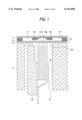
- FIG. 1 is a sectional view showing an embodiment of an ink jet recording head according to the present invention
- FIG. 2 illustrates an embodiment of the present invention
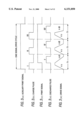
- FIGS. 3(a) to 3(e) illustrate waveforms showing the operation of the embodiment of FIG. 2 for a single drive cycle
- FIG. 4 illustrates the velocities at which a plurality of ink droplets to be combined together in the air with a first ink droplet as a reference
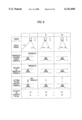
- FIGS. 5(a) to 5(d) illustrate how ink droplets are combined in the embodiment of FIG. 2 and how their velocities change;
- FIG. 6 illustrates another embodiment of the invention
- FIGS. 7(a) to 7(e) illustrate waveforms respectively showing the operation of the embodiment of FIG. 6;
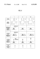
- FIG. 8 is a diagram showing how the meniscus of each ink droplet behaves in the embodiment of FIG. 6;
- FIG. 9 illustrates another embodiment of the present invention in the form of how the meniscus of each ink droplet behaves
- FIGS. 10(a) to 10(e) are diagrams showing the operation of another embodiment of the present invention.
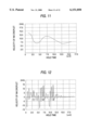
- FIG. 11 is a diagram showing hold time in function of ink droplet velocity
- FIG. 12 is a diagram showing hold time in function of successively jet out ink droplet velocity
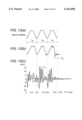
- FIGS. 13(a) to 13(c) illustrate a charge pulse cycle, a natural vibration cycle and a Helmholtz cycle, respectively.
- FIG. 1 shows an embodiment of an ink jet recording head to be used in the invention.
- reference numeral 1 denotes a nozzle plate having a nozzle opening 2 formed therein; 3, a flow path forming plate having a through hole for defining a pressure producing chamber 9, a through hole or groove for defining two ink supply ports 10 that communicate with both sides of the pressure producing chamber 9, and through holes for defining common ink cambers 11, 11 communicating with these ink supply ports 10, 10; and 4, a vibration plate that resiliently deforms while abutted against an end of a piezoelectric vibration element 6.
- the nozzle plate 1 and the vibration plate 4 are fixed to both surfaces of the flow path forming plate 3 so as to be impermeable to liquid to thereby form a substrate unit 5.
- Reference numeral 7 denotes a base, which has an accommodating chamber 8 for accommodating the piezoelectric vibration element 6.
- the piezoelectric vibration element 6 is fixed through a fixing board 13 so that an island portion 4a of the vibration plate 4 can be abutted against an end of the piezoelectric vibration element 6 that is exposed to an opening 12.
- the piezoelectric vibration element 6 operates in a vertical vibration mode, in which displacement takes place in the axial direction of the piezoelectric vibration element. Since the area at the end of the piezoelectric vibration element 6 is extremely small, the capacity of the pressure producing chamber 9 can be designed to be extremely small. As a result, the Helmholtz cycle Tc of the pressure producing chamber 9 can be made smaller than the natural vibration cycle of the piezoelectric vibration element 6. This means that ink in the pressure producing chamber 9 can flow smoothly even if the piezoelectric vibration element 6 is driven at a cycle close to the natural vibration cycle Ta of the piezoelectric vibration element 6. The piezoelectric element is driven at a cycle close to the natural vibration cycle Ta in order to minimize the residual vibration caused after termination of the contraction or expansion of the piezoelectric vibration element 6.
- the flow path impedance Zn of the nozzle opening 2 is set to a value about 1.5 to 3 times larger than the flow path impedance Zr of the ink supply port 10, the movement of the meniscus after the ink has been jet out can be damped rapidly.
- the rapid damping allows the ink droplet jetting cycle to be set to a value extremely small compared with the cycle of a print signal applied from a host.
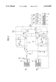
- FIG. 2 is an embodiment of a drive circuit that drives the ink jet recording head.
- reference numeral IN1 denotes an input terminal for an auxiliary print signal (FIG. 3(a)) for contracting the piezoelectric vibration element 6; and IN2 denotes an input terminal for a print signal (FIG. 3(c)) for expanding the contracted piezoelectric vibration element 6.
- a charge pulse generating circuit 20 is connected to the input terminal IN1.
- the charge pulse generating circuit 20 divides a single drive cycle into a plurality of segments.
- the charge pulse generating circuit 20 generates three charge pulses I, II, III, each pulse having a cycle T1, as shown in FIG. 3(b) in this embodiment.
- a first constant current circuit 21 is connected to the output terminal of the charge pulse generating circuit 20 through a level shifting transistor Q1.
- the cycle T1 of each of the charge pulses I, II, III and discharge pulses I', II', III' is quite larger than the Helmholtz cycle Tc, and is selected to have a predetermined value.
- the cycle T1 is set so that the charge pulse generating circuit 20 starts a charge operation and a discharge operation when the pressure producing chamber 9 becomes stable after the ink droplet has been jet out.
- the first constant current circuit 21 includes transistors Q2, Q3 and a resistor R1, and is designed to increase the terminal voltage across a capacitor C at a time constant ⁇ c by charging the capacitor C at a constant current.
- reference numeral 22 denotes a discharge pulse generating circuit which generates pulse signals of a predetermined cycle by dividing the drive cycle into “n" segments (where "n” is an integer that is 2 or greater), or three pulse signals in this embodiment.
- the pulse signals are produced within the drive cycle in synchronism with the rise of a print signal.
- the discharge pulse generating circuit generates a pulse having a time width that can completely discharge the capacitor C at a maximum time constant ⁇ d1 of a time constant adjusting circuit 24, which is described below.
- Reference numeral 23 denotes a second constant current circuit connected to the discharge pulse generating circuit 22.
- the second constant current circuit 23 includes transistors Q4, Q5 and the time constant adjusting circuit 24 having an adjustable resistor.
- the second constant current circuit 23 discharges the electric charges stored in the capacitor C by time constants ⁇ d1, ⁇ d2, ⁇ d3 determined by the time constant adjusting circuit 24.
- the time constant adjusting circuit 24 cyclically changes the resistance in response to the value of an input pulse every time the discharge pulse I', II', or III' is input. That is, in this embodiment, the time constant ⁇ d1 is set in response to the first discharge pulse I', the time constant ⁇ d2 is set in response to the second discharge pulse II', and the time constant ⁇ d3 is set in response to the third discharge pulse III'.
- the time constant adjusting circuit 24 resets the set time constant upon fall of the print signal (c) shown in FIG. 3, and is designed to repeat the time constant changing operation in the same way.
- a terminal of the capacitor C is connected to an output terminal OUT through a current amplifying circuit in which transistors Q6, Q7 and transistors Q8, Q9 are Darlington-connected.
- All the piezoelectric vibration elements 6, 6, 6 . . . are connected to the output terminal OUT through transistors S, S, S . . . that are turned on by signals from a selected signal generating circuit 25.
- the signals of the selected signal generating circuit 25 are obtained by dividing the print signal into a plurality of segments in synchronism with the charge pulses.
- the first charge pulse I of the predetermined cycle T1 is output in synchronism with the rising edge of the auxiliary print signal.
- the first charge pulse I turns on the transistor Q1, which then turns on the transistor Q2 constituting the first constant current circuit 21, so that a constant current flows through the resistor R1 into the capacitor C connected to the transistor Q2.
- the terminal voltage across the capacitor C is amplified by the transistors Q6, Q7 and thereafter applied to the respective piezoelectric vibration elements 6 from the output terminal OUT, so that only predetermined piezoelectric vibration elements 6, 6, 6 . . . are charged at the time constant ⁇ c through the transistors S, S, S . . . selectively turned on by the signals from the selected signal generating circuit 25.
- the pressure producing chamber 9 expands to allow a predetermined quantity of ink to flow into the pressure producing chamber 9 from the common ink chambers 11.
- the transistor Q1 turns off, which in turn stops the charging of the capacitor C.
- a print signal (c) shown in FIG. 3 is fed to the print signal input terminal IN2.
- the first discharge pulse I' with respect to this print signal is generated from the discharge pulse generating circuit 22 and, at the same time, the time constant of the second constant current circuit 23 is set to a value ⁇ d1 by the time constant adjusting circuit 24.
- the transistor Q4 constituting the second constant current circuit 23 turns on, so that the electric charges stored in the capacitor C are discharged at the time constant ⁇ d1. As a result, the terminal voltage across the capacitor C drops linearly at the falling time constant ⁇ d1.
- This falling voltage is applied to the output terminal OUT through the transistors Q8, Q9 to be applied to the respective piezoelectric vibration elements 6.
- the piezoelectric vibration elements 6 with which to form dots are charged, it is only these piezoelectric vibration elements that are discharged at the falling time constant ⁇ d1 through diodes D, D, D . . .
- These piezoelectric vibration elements expand at a velocity defined by the time constant ⁇ d1.
- the pressure producing chambers 9 expand at a velocity defined by the time constant ⁇ d1 as a result of the expansion of the piezoelectric vibration elements 6.
- the pressure producing chambers jet out ink droplets having a velocity V1 out of the corresponding nozzle openings 2 while applying pressure to the ink in the pressure producing chambers 9.
- the aforementioned process is repeated to selectively charge the piezoelectric vibration elements with which to form dots and to supply the ink to the corresponding pressure producing chambers 9 from the common ink chambers 11. Since the second charge pulse II is set to the same time constant ⁇ c, the ink is supplied to the pressure producing chambers 9 in a manner similar to the case of the first charge pulse.
- the second discharge pulse II' is generated in synchronism with the previously received print signal (c) and, at the same time, the discharge time constant of the second constant current circuit 23 is changed to a value ⁇ d2 by the time constant adjusting circuit 24.
- the second discharge pulse II' turns on the transistor Q4 constituting the second constant current circuit 23, discharging the electric charges stored in the capacitor C at the discharge time constant ⁇ d2, which is smaller than the first discharge time constant.
- the piezoelectric vibration elements expand at the time constant ⁇ d2.
- the corresponding pressure producing chambers 9 contract at a velocity defined by the time constant ⁇ d2 and jet ink droplets at a velocity V2 that is faster than the velocity V1 of the ink droplets last jet out.
- the third charge pulse III is applied in synchronism with the auxiliary print signal (a), in a manner similar to the aforementioned case, to expand the pressure producing chambers 9 and to cause the pressure producing chambers 9 to suck in ink.
- the third discharge pulse III' is generated in synchronism with the previously received print signal (c) and, at the same time, the discharge time constant of the second constant current circuit 23 is changed to a value ⁇ d3 by the time constant adjusting circuit 24.
- the third discharge pulse III' drops the terminal voltage across the capacitor at the time constant ⁇ d3 linearly, and the piezoelectric vibration elements 6 expand at a velocity determined by the time constant ⁇ d3.
- ink droplets are jet out at a velocity V3, which is more or less the same as the velocity V2 of the ink droplets last jet out from the corresponding nozzle openings 2.
- the discharge time constants ⁇ d1, ⁇ d2, ⁇ d3 are sequentially decreased, and these values are set so that an ink droplet produced by the second discharge pulse II catches up with an ink droplet produced by the first discharge pulse I before the ink droplet produced by the first discharge pulse I reaches the recording sheet.
- the ink droplets produced by both the first and the second discharge pulses combine together during flight.
- the velocity of the combined ink droplet becomes equal to an average of the velocities of the two ink droplets, the average being smaller than the velocity of the second ink droplet. Therefore, if the velocity V3 of an ink droplet produced by the third discharge pulse III is set to a value larger than the velocity of the second ink droplet, the three ink droplets combine together into a single ink droplet in the air and is deposited on the recording sheet as a single ink droplet.
- a dot formed by the thus combined ink droplet has a quantity of ink substantially three times that of a dot formed by a single ink droplet.
- a dot of a desired size can be formed. If the size of a dot in the carriage travel direction as well as in the sheet forward direction is adjusted optimally in accordance with the quality of paper, white stripes can be prevented by eliminating spaces between dots, irrespective of the minimum travel distances of the carriage drive mechanism and sheet forward mechanism.
- the time constant adjusting circuit 24 Upon input of a next print signal, the time constant adjusting circuit 24 is reset so that the discharge time constant is set to ⁇ d1 again.
- the number of ink droplets with respect to a single auxiliary print signal and a single print signal can be selected as one, two or more depending on the quality of recording paper or on the density of dots to be formed. As a result, not only printing can be performed in accordance with the quality of paper, but also the density of dots can be varied for the same quality of paper.
- FIG. 4 shows such a velocity as to allow three ink droplets to be combined on the recording sheet surface simultaneously during the flight of the three ink droplets.
- the velocity V1 of the first ink droplet is used as a reference when it is assumed that a distance from the nozzle surface of the recording head to the recording sheet, or the so-called platen gap, is set to 1.0 mm.
- sufficiently high quality printing can be performed as long as the velocity of ink droplets ranges from about 6 to 10 m/s.
- the second ink droplet and the third ink droplet are caused to fly at such velocities V2 and V3 as to allow the latter ink droplets to be combined with the first ink droplet without difficulty.
- an ink droplet formed by combining the first and second ink droplets combine with the third ink droplet in the air since the ink droplet formed by combining the first and second ink droplets flies slower than the third ink droplet. Therefore, the third ink droplet catches up with the ink droplet formed by combining the first and second ink droplets.
- a velocity Vf of a combined ink droplet at the time of reaching the recording sheet can be set to 20 m/s.
- the combined ink droplet expands in all directions in accordance with the momentum thereof at the time the combined ink droplet has reached the surface of the recording sheet.
- a large-sized dot can be formed with a small quantity of ink.
- print quality can be improved by preventing mixture of colors between dots by quickening the drying of the ink while increasing the surface area of each dot formed by an ink droplet.
- the ink droplet jetting velocity is adjusted by changing only the discharge time constant while maintaining the ink droplet jetting operation drive cycle constant in the aforementioned embodiment, the ink droplet velocity can be changed by adjusting the quantity of ink forming an ink droplet to be jet out, even if the piezoelectric vibration element 6 expanding and contracting velocity at the time of jetting out the ink droplet is maintained constant.
- FIG. 6 shows an embodiment in the case where the velocity of the ink droplet is changed by adjusting the quantity of ink as described above.
- reference numeral 30 denotes a time constant adjusting circuit arranged in a first constant current circuit 31.
- the time constant adjusting circuit 30 adjusts the time constants of the first constant current circuit 31 to sequentially smaller values ⁇ c1, ⁇ c2, ⁇ c3 by sequentially changing resistances with charge pulses (FIG. 7(b)) from the charge pulse generating circuit 20.
- the time constant adjusting circuit 30 resets the thus adjusted time constants with the next auxiliary print signal.
- Reference numeral 32 in FIG. 6 denotes the second constant current circuit, which discharges the electric charges stored in a capacitor C at a predetermined discharge time constant ⁇ d defined by the resistance of a resistor R2 and the capacitance of the capacitor C.
- the first charge pulse I is output at a predetermined cycle T1 in synchronism with the rising edge of the auxiliary print signal (a).
- the charge time constant ⁇ c1 is set to the first constant current circuit 31, which turns on the transistor Q1 at the same time.
- the capacitor C is then charged by the first constant current circuit 20 at the time constant ⁇ c1. Since this causes the piezoelectric vibration element 6 to contract at the large time constant ⁇ c1, the corresponding pressure producing chamber 9 expands slowly and the ink is therefore allowed into the pressure producing chamber 9 from the common ink chambers 11 while controlling the size of the meniscus to be as small as possible (the sucking of the meniscus indicated in column I in FIG. 8).
- the transistor Q1 Upon elapse of a time defined by the pulse width of the charge pulse I, the transistor Q1 turns off, which in turn stops the charging of the capacitor C.
- a print signal (FIG. 7(c)) is applied to the print signal input terminal IN2.
- the first discharge pulse I' is output from the discharge pulse generating circuit 32, which turns on the transistor Q4 of the second constant current circuit 32.
- the electric charges stored in the capacitor C are thereafter discharged at the predetermined time constant ⁇ d defined by the resistor R2.
- the terminal voltage across the capacitor C drops linearly at the time constant ⁇ d.
- the piezoelectric vibration element 6 expands at a velocity defined by the time constant ⁇ d of the discharge current to cause the corresponding pressure producing chamber 9 to contract and to allow the corresponding nozzle opening 2 to jet out an ink droplet having a velocity of V1.
- the meniscus sucking force is small because the time constant ⁇ c1 is large, which in turn causes the meniscus to return quickly to the edge of the nozzle opening (the return of the meniscus indicated in column I in FIG. 8).
- a large quantity m1 of ink is jet out (the jetting out of the ink droplet indicated in column I in FIG. 8), and the velocity V1 of the ink droplet is low.
- the time constant of the time constant adjusting circuit 30 is changed to a value ⁇ c2 that is smaller than the last time constant ⁇ c1.
- the last process is repeated to selectively charge only the piezoelectric vibration elements 6 with which to form dots.
- the pressure producing chamber 9 expands slightly rapidly by the time constant ⁇ c2, and this increases the meniscus sucking force compared with the meniscus sucking force in the last case (the sucking of the meniscus indicated in column II in FIG. 8).
- the second discharge pulse II' is applied, so that the piezoelectric vibration element 6 expands at the predetermined velocity defined by the time constant ⁇ d to cause the corresponding pressure producing chamber 9 to contract.
- the meniscus sucking force is slightly larger in the current case than in the last case, the second discharge pulse II' is applied immediately. Therefore, a return of the meniscus becomes slightly small (the return of the meniscus indicated in column II in FIG. 8), decreasing a quantity m2 of ink in an ink droplet compared with the quantity m1 in the last case.
- the ink droplet is jet out at a velocity V2 that is faster than the velocity V1 in the last case (the jetting of the ink droplet indicated in column II in FIG. 8).
- the time constant adjusting circuit 30 changes the third time constant ⁇ c3 in response to the third charge pulse III generated in synchronism with the auxiliary print signal (a) in a manner similar to the last case. Simultaneously therewith, the pressure producing chamber 9 is expanded by the time constant ⁇ c3 to cause the pressure producing chamber 9 to suck the ink.
- the third discharge pulse III' is output in synchronism with the previously received print signal (c), causing an ink droplet to be jet out of the corresponding nozzle opening 2.
- a return of the meniscus is reduced by an amount comparable to the increase in sucking force (the return of the meniscus indicated in column III in FIG. 8).
- the quantity m3 of ink in an ink droplet to be jet out is reduced, and the ink droplet flies at a velocity V3 that is faster than the velocity V2 of the last ink droplet (the jetting of the ink droplet indicated in column III in FIG. 8).
- the second and third ink droplets catch up with the first ink droplet successively before the first ink droplet reaches the recording sheet. This allows the three ink droplets to be combined together in the air and to deposit on the recording sheet.
- the above embodiment is suitably applied to the adjustment of tones during the printing operations performed at the same resolution with the hold time T2 (a period from timing a to timing b in FIG. 8) of the maximum voltage at the charging end maintained constant. If the resolution itself is to be changed, a time T3 from the start of charge timing to the ink droplet jet start timing (timing b in FIG. 9) may be maintained constant to make the quantities of successive ink droplets substantially equal to one another (to the extent possible), and the velocity of each successive ink droplet may be increased.
- printing at a resolution of 1440 dpi can be performed if a single ink droplet is used to form a single dot; printing at a resolution of 720 dpi can be performed if two ink droplets are used to form a single dot by causing the two ink droplets to be combined in the air; and printing at a resolution of 360 dpi can be performed if three ink droplets are used to form a single dot by causing the three ink droplets to be combined in the air.
- the velocity of an ink droplet is adjusted by changing the discharge time constant or the charge time constant in the aforementioned embodiment. If both the discharge time constant and the charge time constant are adjusted in such a manner that the velocity of an ink droplet jet out thereafter becomes faster, the size of the ink droplets can be adjusted freely. According to the present invention, a wide variety of types of recording sheets and dot sizes can be accommodated.
- an ink droplet that is jet out next has a faster velocity in the aforementioned embodiment.
- "n" ink droplets can be combined in the air. That is, if only the first ink droplet is jet out slowly and the succeeding second and third ink droplets are jet out faster than the first ink droplet in such a manner that ink droplets jet out second and thereafter are jet out at the same velocity, i.e., the second ink droplet and "n"th ink droplet are jet out at the same velocity that is faster than that of the first ink droplet (FIG. 5(a)), these "n" ink droplets can be combined together in the air.
- FIGS. 10(a) to 10(e) show another embodiment of the invention in the form of waveforms.
- This embodiment is characterized as using a plurality of waveforms in which both a charge time constant ⁇ c4 for contracting the piezoelectric vibration elements to expand the corresponding pressure producing chambers, and a discharge time constant ⁇ d4 for expanding the piezoelectric vibration elements to contract the corresponding pressure producing chambers, are maintained constant and in which hold times T5, T6 are set to be different. That is, in this embodiment, first, second and third drive waveforms I, II, III are applied at a predetermined cycle T1.
- the charge time constant ⁇ c4 is set to 8 ⁇ s; the discharge time constant ⁇ d4 is set to 8 ⁇ s; the hold time T5 of the first drive waveform I is set to 12 ⁇ s; and the hold time T6 of each of the second and third drive waveforms II, III is set to 8 ⁇ s.
- the velocity of an ink droplet jet out by the first drive waveform is equal to 6.5 m/s ((1) in FIG. 12) and the velocities of ink droplets jet out by the second and third drive waveforms are substantially equal to 13 m/s ((2) and (3) in FIG. 12), which are minimum velocities for keeping satisfactory print quality.
- the ink droplets produced by the first and second drive waveforms I, II are combined together in the air.
- the combined ink droplet flies at a velocity, i.e., about 9 m/s, which is an average of the first and second ink droplet velocities and which is lower than the velocity of the second ink droplet.
- the ink droplet produced by the third drive waveform III which is the same waveform as the second drive waveform II, is combined with the combined ink droplet formed of the first and second ink droplets during their flight to reach the recording medium with the three ink droplets combined together.
- the charge time constant ⁇ c4 and the discharge time constant ⁇ d4 which are both relatively hard to design and adjust in terms of forming a circuit configuration, are maintained constant, but the cycle of each drive waveform is also maintained constant. Therefore, the designing of the drive circuit can be simplified.
- the invention is characterized as including: a recording head having a piezoelectric vibration element whose natural vibration cycle is Ta and a pressure producing chamber whose Helmholtz cycle is Tc, the pressure producing chamber being expanded or contracted by displacement of the piezoelectric vibration element to thereby suck in ink from a common ink chamber and to jet out an ink droplet from a nozzle opening; a first drive signal outputting means for outputting a first signal for contracting the piezoelectric vibration element at a predetermined velocity; a second drive signal outputting means for outputting a second signal for expanding the piezoelectric vibration element at a predetermined velocity; a pulse signal generating means for dividing a single recording head drive period into "n" segments (where "n” is an integer that is 2 or greater) and outputting a pulse signal whose cycle Tp is larger than the Helmholtz cycle Tc in synchronism with a dot forming signal from outside; and a circuit constant adjusting means for adjusting a time
- the recording head is driven regularly for a plurality of times at a predetermined cycle with respect to a single print signal by generating a plurality of pulse signals, each pulse signal having the same cycle Tp that is larger than the Helmholtz cycle Tc, within a single drive period.
- areal gradation can be implemented by allowing a plurality of ink droplets to be combined in the air without requiring that the cycle at which to jet out each ink droplet to be changed.
Landscapes
- Particle Formation And Scattering Control In Inkjet Printers (AREA)
- Ink Jet Recording Methods And Recording Media Thereof (AREA)
Priority Applications (1)
| Application Number | Priority Date | Filing Date | Title |
|---|---|---|---|
| US09/161,492 US6086189A (en) | 1995-04-14 | 1998-09-28 | Ink jet recording apparatus for adjusting time constant of expansion/contraction of piezoelectric element |
Applications Claiming Priority (4)
| Application Number | Priority Date | Filing Date | Title |
|---|---|---|---|
| JP11398795 | 1995-04-14 | ||
| JP7-113987 | 1995-04-14 | ||
| JP8090515A JPH08336970A (ja) | 1995-04-14 | 1996-03-18 | インクジェット式記録装置 |
| JP8-090515 | 1996-03-18 |
Related Child Applications (1)
| Application Number | Title | Priority Date | Filing Date |
|---|---|---|---|
| US09/161,492 Division US6086189A (en) | 1995-04-14 | 1998-09-28 | Ink jet recording apparatus for adjusting time constant of expansion/contraction of piezoelectric element |
Publications (1)
| Publication Number | Publication Date |
|---|---|
| US6151050A true US6151050A (en) | 2000-11-21 |
Family
ID=26431994
Family Applications (2)
| Application Number | Title | Priority Date | Filing Date |
|---|---|---|---|
| US08/631,231 Expired - Lifetime US6151050A (en) | 1995-04-14 | 1996-04-12 | Ink jet recording apparatus for adjusting time constant of expansion/contraction of piezoelectric element |
| US09/161,492 Expired - Lifetime US6086189A (en) | 1995-04-14 | 1998-09-28 | Ink jet recording apparatus for adjusting time constant of expansion/contraction of piezoelectric element |
Family Applications After (1)
| Application Number | Title | Priority Date | Filing Date |
|---|---|---|---|
| US09/161,492 Expired - Lifetime US6086189A (en) | 1995-04-14 | 1998-09-28 | Ink jet recording apparatus for adjusting time constant of expansion/contraction of piezoelectric element |
Country Status (6)
| Country | Link |
|---|---|
| US (2) | US6151050A (fr) |
| EP (1) | EP0737586B1 (fr) |
| JP (1) | JPH08336970A (fr) |
| AT (1) | ATE185517T1 (fr) |
| CA (1) | CA2174071C (fr) |
| DE (1) | DE69604611T2 (fr) |
Cited By (27)
| Publication number | Priority date | Publication date | Assignee | Title |
|---|---|---|---|---|
| US6382753B1 (en) * | 1999-05-28 | 2002-05-07 | Seiko Epson Corporation | Ink-jet recording head driving method and ink-jet recording apparatus |
| US6488349B1 (en) * | 1999-09-21 | 2002-12-03 | Matsushita Electric Industrial Co., Ltd. | Ink-jet head and ink-jet type recording apparatus |
| US6517176B1 (en) | 1999-09-30 | 2003-02-11 | Seiko Epson Corporation | Liquid jetting apparatus |
| US6669324B1 (en) | 2002-11-25 | 2003-12-30 | Lexmark International, Inc. | Method and apparatus for optimizing a relationship between fire energy and drop velocity in an imaging device |
| US6709091B1 (en) | 1996-08-29 | 2004-03-23 | Brother Kogyo Kabushiki Kaisha | Ink ejection device and driving method therefor |
| US6719388B2 (en) * | 2002-01-16 | 2004-04-13 | Xerox Corporation | Fail-safe circuit for dynamic smartpower integrated circuits |
| US6786564B2 (en) * | 2000-03-31 | 2004-09-07 | Fuji Photo Film Co., Ltd. | Inkjet printer, drive method and drive device for same |
| US20040183839A1 (en) * | 2002-03-25 | 2004-09-23 | Gottfurcht Elliot A. | Apparatus and method for simple wide-area network navigation |
| US20040207671A1 (en) * | 2001-09-20 | 2004-10-21 | Masanori Kusunoki | Image recording apparatus and head driving control apparatus |
| US20050078131A1 (en) * | 2003-10-14 | 2005-04-14 | Tony Cruz-Uribe | Method and a system for single ligament fluid dispensing |
| US20050122069A1 (en) * | 1998-12-17 | 2005-06-09 | Minolta Co., Ltd | Discharging circuit for a piezoelectric device |
| US7194698B2 (en) | 1999-11-15 | 2007-03-20 | Elliot A. Gottfurcht | Method to advertise and search on television for web content using a simplified interface |
| US20070080978A1 (en) * | 2005-10-12 | 2007-04-12 | Takahiro Yoshida | Image forming apparatus having droplet speed control |
| US20070211092A1 (en) * | 2005-03-04 | 2007-09-13 | Mitsuru Shingyohuchi | Imaging Apparatus |
| CN100337826C (zh) * | 2003-11-06 | 2007-09-19 | 佳能株式会社 | 记录头用基板、记录头、头墨盒、驱动方法和记录装置 |
| US7281778B2 (en) | 2004-03-15 | 2007-10-16 | Fujifilm Dimatix, Inc. | High frequency droplet ejection device and method |
| US20070285448A1 (en) * | 2006-06-12 | 2007-12-13 | Fuji Xerox Co., Ltd. | Liquid drop expelling head and image forming device provided therewith |
| US7441196B2 (en) | 1999-11-15 | 2008-10-21 | Elliot Gottfurcht | Apparatus and method of manipulating a region on a wireless device screen for viewing, zooming and scrolling internet content |
| US20100149272A1 (en) * | 2008-12-17 | 2010-06-17 | Robert Lee Cornell | Uv-curable coatings and methods for applying uv-curable coatings using thermal micro-fluid ejection heads |
| US7988247B2 (en) | 2007-01-11 | 2011-08-02 | Fujifilm Dimatix, Inc. | Ejection of drops having variable drop size from an ink jet printer |
| US20120081430A1 (en) * | 2010-10-01 | 2012-04-05 | Seiko Epson Corporation | Liquid ejecting apparatus and controlling method thereof |
| US8393702B2 (en) | 2009-12-10 | 2013-03-12 | Fujifilm Corporation | Separation of drive pulses for fluid ejector |
| US8452653B1 (en) | 2000-03-15 | 2013-05-28 | Personal Data Network Corporation | Method for providing information and recommendations based on user activity |
| US8491076B2 (en) | 2004-03-15 | 2013-07-23 | Fujifilm Dimatix, Inc. | Fluid droplet ejection devices and methods |
| US8708441B2 (en) | 2004-12-30 | 2014-04-29 | Fujifilm Dimatix, Inc. | Ink jet printing |
| US9090059B1 (en) * | 2014-03-07 | 2015-07-28 | Seiko Epson Corporation | Printing apparatus and control method and program thereof |
| US20180222185A1 (en) * | 2017-02-08 | 2018-08-09 | Roland Dg Corporation | Liquid injection device and inkjet printer including the same |
Families Citing this family (32)
| Publication number | Priority date | Publication date | Assignee | Title |
|---|---|---|---|---|
| WO1998022288A1 (fr) * | 1996-11-18 | 1998-05-28 | Seiko Epson Corporation | Tete d'ecriture a jet d'encre |
| JPH10250074A (ja) * | 1997-03-18 | 1998-09-22 | Fujitsu Ltd | 圧電素子駆動回路及びインクジェット記録装置 |
| GB9802871D0 (en) | 1998-02-12 | 1998-04-08 | Xaar Technology Ltd | Operation of droplet deposition apparatus |
| JP3530717B2 (ja) * | 1997-06-19 | 2004-05-24 | キヤノン株式会社 | インクジェット記録方法及び装置 |
| US6375309B1 (en) | 1997-07-31 | 2002-04-23 | Canon Kabushiki Kaisha | Liquid discharge apparatus and method for sequentially driving multiple electrothermal converting members |
| JP3161404B2 (ja) | 1997-12-26 | 2001-04-25 | 日本電気株式会社 | インク滴径制御方法およびインクジェット記録ヘッド |
| AU769733B2 (en) * | 1998-02-12 | 2004-02-05 | Xaar Technology Limited | Operation of droplet deposition apparatus |
| GB2338928B (en) | 1998-07-02 | 2000-08-09 | Tokyo Electric Co Ltd | A driving method of an ink-jet head |
| GB2338927B (en) * | 1998-07-02 | 2000-08-09 | Tokyo Electric Co Ltd | A driving method of an ink-jet head |
| JP2000135800A (ja) * | 1998-08-28 | 2000-05-16 | Hitachi Koki Co Ltd | オンデマンド型マルチノズルインクジェットヘッドの駆動方法 |
| JP2000127390A (ja) * | 1998-10-30 | 2000-05-09 | Nec Corp | インクジェット記録ヘッドの駆動方法 |
| DE69931875T2 (de) | 1998-11-12 | 2007-06-06 | Seiko Epson Corp. | Tintenstrahlaufzeichnungsgerät |
| US6517267B1 (en) * | 1999-08-23 | 2003-02-11 | Seiko Epson Corporation | Printing process using a plurality of drive signal types |
| JP4748895B2 (ja) * | 1999-09-21 | 2011-08-17 | パナソニック株式会社 | インクジェットヘッド及びインクジェット式記録装置 |
| US6478395B2 (en) * | 1999-12-01 | 2002-11-12 | Seiko Epson Corporation | Liquid jetting apparatus |
| JP2002086765A (ja) * | 2000-09-13 | 2002-03-26 | Matsushita Electric Ind Co Ltd | インクジェットヘッド及びインクジェット式記録装置 |
| EP1195249B1 (fr) * | 2000-10-06 | 2005-12-21 | Seiko Epson Corporation | Procédé de commande d'une tête d'enregistrement à jet d'encre et appareil d'enregistrement à jet d'encre pour sa mise en oeuvre |
| US6793311B2 (en) | 2001-10-05 | 2004-09-21 | Matsushita Electric Industrial Co., Ltd. | Ink jet recording apparatus |
| EP1473290A4 (fr) * | 2002-02-08 | 2007-10-03 | Sumitomo Chemical Co | Procede de production de compose d'epoxyde |
| JP2005014431A (ja) * | 2003-06-26 | 2005-01-20 | Ricoh Co Ltd | 画像形成装置 |
| US7344218B2 (en) | 2003-11-06 | 2008-03-18 | Canon Kabushiki Kaisha | Printhead driving method, printhead substrate, printhead, head cartridge and printing apparatus |
| JP4529120B2 (ja) | 2004-03-02 | 2010-08-25 | セイコーエプソン株式会社 | 液体噴射装置 |
| JP4975258B2 (ja) * | 2005-02-18 | 2012-07-11 | 株式会社リコー | 画像形成装置 |
| DE102006045060A1 (de) * | 2006-09-21 | 2008-04-10 | Kba-Metronic Ag | Verfahren und Vorrichtung zur Erzeugung von Tintentropfen mit variablen Tropfenvolumen |
| JP5534930B2 (ja) | 2010-05-12 | 2014-07-02 | 大日本スクリーン製造株式会社 | インクジェットプリンタおよび画像記録方法 |
| US8356869B2 (en) * | 2010-06-25 | 2013-01-22 | Xerox Corporation | Body diode forward conduction prevention |
| JP5410490B2 (ja) * | 2011-09-30 | 2014-02-05 | 富士フイルム株式会社 | 液体吐出ヘッドの駆動装置及び駆動方法、液体吐出装置、並びにインクジェット装置 |
| JP5845968B2 (ja) * | 2012-02-27 | 2016-01-20 | 株式会社リコー | 液滴量測定装置、液滴量測定方法、および液滴吐出ヘッドの製造方法 |
| JP6024906B2 (ja) * | 2013-01-09 | 2016-11-16 | 株式会社リコー | 画像形成装置、ヘッド駆動制御装置、ヘッド駆動制御方法 |
| SG11201800283TA (en) * | 2015-07-13 | 2018-02-27 | Jan Franck | Method for actuating an ink-jet print head |
| JP6659508B2 (ja) * | 2016-09-28 | 2020-03-04 | 京セラ株式会社 | 液体吐出ヘッド、およびそれを用いた記録装置 |
| JP7643121B2 (ja) * | 2021-03-22 | 2025-03-11 | セイコーエプソン株式会社 | 液体吐出装置 |
Citations (13)
| Publication number | Priority date | Publication date | Assignee | Title |
|---|---|---|---|---|
| JPS5820465A (ja) * | 1981-07-30 | 1983-02-05 | Nec Corp | 圧電型印字ヘツド駆動回路 |
| JPS59133066A (ja) * | 1982-12-27 | 1984-07-31 | データプロダクツ コーポレイション | インク滴の量の制御方法 |
| US4513299A (en) * | 1983-12-16 | 1985-04-23 | International Business Machines Corporation | Spot size modulation using multiple pulse resonance drop ejection |
| GB2157623A (en) * | 1984-04-16 | 1985-10-30 | Exxon Research Engineering Co | Method of operating an ink jet apparatus to control dot size |
| EP0194852A2 (fr) * | 1985-03-11 | 1986-09-17 | Dataproducts Corporation | Système d'entraînement pour appareil à jet d'encre |
| US4714935A (en) * | 1983-05-18 | 1987-12-22 | Canon Kabushiki Kaisha | Ink-jet head driving circuit |
| JPH0574016A (ja) * | 1991-09-10 | 1993-03-26 | Sony Corp | カセツト装着装置 |
| JPH05338165A (ja) * | 1992-06-05 | 1993-12-21 | Ricoh Co Ltd | 液体噴射記録ヘッドの駆動方法 |
| JPH05338164A (ja) * | 1992-06-04 | 1993-12-21 | Ricoh Co Ltd | インクジェットヘッドの駆動装置及びその駆動方法 |
| US5285215A (en) * | 1982-12-27 | 1994-02-08 | Exxon Research And Engineering Company | Ink jet apparatus and method of operation |
| US5552809A (en) * | 1993-01-25 | 1996-09-03 | Seiko Epson Corporation | Method for driving ink jet recording head and apparatus therefor |
| US5610637A (en) * | 1992-09-29 | 1997-03-11 | Ricoh Company, Ltd. | Ink jet recording method |
| US5668579A (en) * | 1993-06-16 | 1997-09-16 | Seiko Epson Corporation | Apparatus for and a method of driving an ink jet head having an electrostatic actuator |
-
1996
- 1996-03-18 JP JP8090515A patent/JPH08336970A/ja active Pending
- 1996-04-12 CA CA002174071A patent/CA2174071C/fr not_active Expired - Lifetime
- 1996-04-12 US US08/631,231 patent/US6151050A/en not_active Expired - Lifetime
- 1996-04-12 EP EP96105806A patent/EP0737586B1/fr not_active Expired - Lifetime
- 1996-04-12 DE DE69604611T patent/DE69604611T2/de not_active Expired - Lifetime
- 1996-04-12 AT AT96105806T patent/ATE185517T1/de not_active IP Right Cessation
-
1998
- 1998-09-28 US US09/161,492 patent/US6086189A/en not_active Expired - Lifetime
Patent Citations (15)
| Publication number | Priority date | Publication date | Assignee | Title |
|---|---|---|---|---|
| JPS5820465A (ja) * | 1981-07-30 | 1983-02-05 | Nec Corp | 圧電型印字ヘツド駆動回路 |
| JPS59133066A (ja) * | 1982-12-27 | 1984-07-31 | データプロダクツ コーポレイション | インク滴の量の制御方法 |
| EP0115180A2 (fr) * | 1982-12-27 | 1984-08-08 | Dataproducts Corporation | Production d'un jet d'encre |
| US5285215A (en) * | 1982-12-27 | 1994-02-08 | Exxon Research And Engineering Company | Ink jet apparatus and method of operation |
| US4714935A (en) * | 1983-05-18 | 1987-12-22 | Canon Kabushiki Kaisha | Ink-jet head driving circuit |
| US4513299A (en) * | 1983-12-16 | 1985-04-23 | International Business Machines Corporation | Spot size modulation using multiple pulse resonance drop ejection |
| GB2157623A (en) * | 1984-04-16 | 1985-10-30 | Exxon Research Engineering Co | Method of operating an ink jet apparatus to control dot size |
| US4686539A (en) * | 1985-03-11 | 1987-08-11 | Schmidle Lisa M | Multipulsing method for operating an ink jet apparatus for printing at high transport speeds |
| EP0194852A2 (fr) * | 1985-03-11 | 1986-09-17 | Dataproducts Corporation | Système d'entraînement pour appareil à jet d'encre |
| JPH0574016A (ja) * | 1991-09-10 | 1993-03-26 | Sony Corp | カセツト装着装置 |
| JPH05338164A (ja) * | 1992-06-04 | 1993-12-21 | Ricoh Co Ltd | インクジェットヘッドの駆動装置及びその駆動方法 |
| JPH05338165A (ja) * | 1992-06-05 | 1993-12-21 | Ricoh Co Ltd | 液体噴射記録ヘッドの駆動方法 |
| US5610637A (en) * | 1992-09-29 | 1997-03-11 | Ricoh Company, Ltd. | Ink jet recording method |
| US5552809A (en) * | 1993-01-25 | 1996-09-03 | Seiko Epson Corporation | Method for driving ink jet recording head and apparatus therefor |
| US5668579A (en) * | 1993-06-16 | 1997-09-16 | Seiko Epson Corporation | Apparatus for and a method of driving an ink jet head having an electrostatic actuator |
Non-Patent Citations (6)
| Title |
|---|
| Patent Abstracts of Japan, vol. 18, No. 173 (M 1581), Mar. 24, 1994 & JP A 05 0338164 (Ricoh Co Ltd), Dec. 21, 1993, *abstract. * |
| Patent Abstracts of Japan, vol. 18, No. 173 (M 1581), Mar. 24, 1994, & JP A 05 338165 (Ricoh Co Ltd), Dec. 21, 1993, *abstract. * |
| Patent Abstracts of Japan, vol. 18, No. 173 (M-1581), Mar. 24, 1994 & JP-A-05 0338164 (Ricoh Co Ltd), Dec. 21, 1993, *abstract. |
| Patent Abstracts of Japan, vol. 18, No. 173 (M-1581), Mar. 24, 1994, & JP-A-05 338165 (Ricoh Co Ltd), Dec. 21, 1993, *abstract. |
| Patent Abstracts of Japan, vol. 7, No. 98 (M 210), Apr. 26, 1983, & JP A 58 020465 (Nippon Denki K.K.), Feb. 5, 1983, *abstract. * |
| Patent Abstracts of Japan, vol. 7, No. 98 (M-210), Apr. 26, 1983, & JP-A-58 020465 (Nippon Denki K.K.), Feb. 5, 1983, *abstract. |
Cited By (39)
| Publication number | Priority date | Publication date | Assignee | Title |
|---|---|---|---|---|
| US6709091B1 (en) | 1996-08-29 | 2004-03-23 | Brother Kogyo Kabushiki Kaisha | Ink ejection device and driving method therefor |
| US7075210B2 (en) * | 1998-12-17 | 2006-07-11 | Minolta Co., Ltd. | Discharging circuit for a piezoelectric device |
| US20050122069A1 (en) * | 1998-12-17 | 2005-06-09 | Minolta Co., Ltd | Discharging circuit for a piezoelectric device |
| US6382753B1 (en) * | 1999-05-28 | 2002-05-07 | Seiko Epson Corporation | Ink-jet recording head driving method and ink-jet recording apparatus |
| US6488349B1 (en) * | 1999-09-21 | 2002-12-03 | Matsushita Electric Industrial Co., Ltd. | Ink-jet head and ink-jet type recording apparatus |
| US6517176B1 (en) | 1999-09-30 | 2003-02-11 | Seiko Epson Corporation | Liquid jetting apparatus |
| US6572210B2 (en) | 1999-09-30 | 2003-06-03 | Seiko Epson Corporation | Liquid jetting apparatus |
| US7441196B2 (en) | 1999-11-15 | 2008-10-21 | Elliot Gottfurcht | Apparatus and method of manipulating a region on a wireless device screen for viewing, zooming and scrolling internet content |
| US7194698B2 (en) | 1999-11-15 | 2007-03-20 | Elliot A. Gottfurcht | Method to advertise and search on television for web content using a simplified interface |
| US8452653B1 (en) | 2000-03-15 | 2013-05-28 | Personal Data Network Corporation | Method for providing information and recommendations based on user activity |
| US6786564B2 (en) * | 2000-03-31 | 2004-09-07 | Fuji Photo Film Co., Ltd. | Inkjet printer, drive method and drive device for same |
| US20040207671A1 (en) * | 2001-09-20 | 2004-10-21 | Masanori Kusunoki | Image recording apparatus and head driving control apparatus |
| US7249816B2 (en) | 2001-09-20 | 2007-07-31 | Ricoh Company, Ltd. | Image recording apparatus and head driving control apparatus |
| US6719388B2 (en) * | 2002-01-16 | 2004-04-13 | Xerox Corporation | Fail-safe circuit for dynamic smartpower integrated circuits |
| US20040183839A1 (en) * | 2002-03-25 | 2004-09-23 | Gottfurcht Elliot A. | Apparatus and method for simple wide-area network navigation |
| US6669324B1 (en) | 2002-11-25 | 2003-12-30 | Lexmark International, Inc. | Method and apparatus for optimizing a relationship between fire energy and drop velocity in an imaging device |
| US20050078131A1 (en) * | 2003-10-14 | 2005-04-14 | Tony Cruz-Uribe | Method and a system for single ligament fluid dispensing |
| US7219970B2 (en) * | 2003-10-14 | 2007-05-22 | Hewlett-Packard Development Company, L.P. | Method and a system for single ligament fluid dispensing |
| US20070200884A1 (en) * | 2003-10-14 | 2007-08-30 | Tony Cruz-Uribe | Method and a system for single ligament fluid dispensing |
| CN100337826C (zh) * | 2003-11-06 | 2007-09-19 | 佳能株式会社 | 记录头用基板、记录头、头墨盒、驱动方法和记录装置 |
| US7281778B2 (en) | 2004-03-15 | 2007-10-16 | Fujifilm Dimatix, Inc. | High frequency droplet ejection device and method |
| US8491076B2 (en) | 2004-03-15 | 2013-07-23 | Fujifilm Dimatix, Inc. | Fluid droplet ejection devices and methods |
| US8459768B2 (en) | 2004-03-15 | 2013-06-11 | Fujifilm Dimatix, Inc. | High frequency droplet ejection device and method |
| US8708441B2 (en) | 2004-12-30 | 2014-04-29 | Fujifilm Dimatix, Inc. | Ink jet printing |
| US9381740B2 (en) | 2004-12-30 | 2016-07-05 | Fujifilm Dimatix, Inc. | Ink jet printing |
| US20070211092A1 (en) * | 2005-03-04 | 2007-09-13 | Mitsuru Shingyohuchi | Imaging Apparatus |
| US8057001B2 (en) | 2005-03-04 | 2011-11-15 | Ricoh Company, Ltd. | Imaging apparatus |
| US20070080978A1 (en) * | 2005-10-12 | 2007-04-12 | Takahiro Yoshida | Image forming apparatus having droplet speed control |
| US7520579B2 (en) | 2005-10-12 | 2009-04-21 | Ricoh Company, Ltd. | Image forming apparatus having droplet speed control |
| US20070285448A1 (en) * | 2006-06-12 | 2007-12-13 | Fuji Xerox Co., Ltd. | Liquid drop expelling head and image forming device provided therewith |
| US7918520B2 (en) * | 2006-06-12 | 2011-04-05 | Fuji Xerox Co., Ltd. | Liquid drop expelling head and image forming device provided therewith |
| US7988247B2 (en) | 2007-01-11 | 2011-08-02 | Fujifilm Dimatix, Inc. | Ejection of drops having variable drop size from an ink jet printer |
| US20100149272A1 (en) * | 2008-12-17 | 2010-06-17 | Robert Lee Cornell | Uv-curable coatings and methods for applying uv-curable coatings using thermal micro-fluid ejection heads |
| US8191987B2 (en) * | 2008-12-17 | 2012-06-05 | Lexmark International, Inc. | UV-curable coatings and methods for applying UV-curable coatings using thermal micro-fluid ejection heads |
| US8393702B2 (en) | 2009-12-10 | 2013-03-12 | Fujifilm Corporation | Separation of drive pulses for fluid ejector |
| US20120081430A1 (en) * | 2010-10-01 | 2012-04-05 | Seiko Epson Corporation | Liquid ejecting apparatus and controlling method thereof |
| US9090059B1 (en) * | 2014-03-07 | 2015-07-28 | Seiko Epson Corporation | Printing apparatus and control method and program thereof |
| US20180222185A1 (en) * | 2017-02-08 | 2018-08-09 | Roland Dg Corporation | Liquid injection device and inkjet printer including the same |
| US10449761B2 (en) * | 2017-02-08 | 2019-10-22 | Roland Dg Corporation | Liquid ejection device and inkjet printer including the same |
Also Published As
| Publication number | Publication date |
|---|---|
| JPH08336970A (ja) | 1996-12-24 |
| ATE185517T1 (de) | 1999-10-15 |
| EP0737586A1 (fr) | 1996-10-16 |
| DE69604611D1 (de) | 1999-11-18 |
| US6086189A (en) | 2000-07-11 |
| DE69604611T2 (de) | 2000-06-08 |
| EP0737586B1 (fr) | 1999-10-13 |
| CA2174071C (fr) | 2004-09-21 |
| CA2174071A1 (fr) | 1996-10-15 |
Similar Documents
| Publication | Publication Date | Title |
|---|---|---|
| US6151050A (en) | Ink jet recording apparatus for adjusting time constant of expansion/contraction of piezoelectric element | |
| US5521619A (en) | Ink jet type recording apparatus that controls into meniscus vibrations | |
| JP3292223B2 (ja) | インクジェット式記録ヘッドの駆動方法、及びその装置 | |
| US5453767A (en) | Method for forming ink droplets in ink-jet type printer and ink-jet type recording device | |
| US6290315B1 (en) | Method of driving an ink jet recording head | |
| JP3156583B2 (ja) | インクジェット式印字ヘッドの駆動装置 | |
| JPH04250045A (ja) | ドロップ・オン・デマンド型インク・ジェット・プリンタ | |
| WO1997018953A1 (fr) | Circuit et procede de commande d'une tete d'impression a jet d'encre | |
| JP6848976B2 (ja) | インクジェット記録装置及びインクジェット記録方法 | |
| US6203132B1 (en) | Ink jet recording apparatus | |
| JP2014019050A (ja) | インクジェット記録装置及びインクジェット式記録ヘッドの駆動方法 | |
| US6419336B1 (en) | Ink ejector | |
| CN102133813A (zh) | 喷液装置 | |
| JP3241352B2 (ja) | インクジェットヘッド及びインクジェット式記録装置 | |
| JP2019059131A (ja) | 液体吐出装置 | |
| JP3233197B2 (ja) | インクジェット式記録装置 | |
| US6241345B1 (en) | Ink jet recording head controlling diameter of an ink droplet | |
| JP3500692B2 (ja) | インクジェット記録装置 | |
| JPH11157064A (ja) | インクジェット記録ヘッドの駆動装置及び駆動方法 | |
| JP2785727B2 (ja) | インクジェット式プリントヘッド及びその駆動方法 | |
| JP3525011B2 (ja) | インクジェット記録ヘッドの駆動方法 | |
| JP5251562B2 (ja) | 液体吐出装置、及び、液体吐出装置の制御方法 | |
| JP2889377B2 (ja) | インクジェットヘッドの駆動回路およびその駆動方法 | |
| JP2003118113A (ja) | インクジェット式記録装置、及び、その駆動方法 | |
| JP3381438B2 (ja) | インクジェット記録装置 |
Legal Events
| Date | Code | Title | Description |
|---|---|---|---|
| AS | Assignment |
Owner name: SEIKO EPSON CORPORATION, JAPAN Free format text: ASSIGNMENT OF ASSIGNORS INTEREST;ASSIGNORS:HOSONO, SATORU;SARUTA, TOSHIHISA;REEL/FRAME:008063/0109 Effective date: 19960603 |
|
| STCF | Information on status: patent grant |
Free format text: PATENTED CASE |
|
| FPAY | Fee payment |
Year of fee payment: 4 |
|
| FPAY | Fee payment |
Year of fee payment: 8 |
|
| FEPP | Fee payment procedure |
Free format text: PAYOR NUMBER ASSIGNED (ORIGINAL EVENT CODE: ASPN); ENTITY STATUS OF PATENT OWNER: LARGE ENTITY |
|
| FPAY | Fee payment |
Year of fee payment: 12 |