US6155739A - Temporary connection device for universal joint - Google Patents
Temporary connection device for universal joint Download PDFInfo
- Publication number
- US6155739A US6155739A US09/100,875 US10087598A US6155739A US 6155739 A US6155739 A US 6155739A US 10087598 A US10087598 A US 10087598A US 6155739 A US6155739 A US 6155739A
- Authority
- US
- United States
- Prior art keywords
- shaft
- shaped groove
- yoke
- bolt
- connection device
- Prior art date
- Legal status (The legal status is an assumption and is not a legal conclusion. Google has not performed a legal analysis and makes no representation as to the accuracy of the status listed.)
- Expired - Lifetime
Links
Images




Classifications
-
- B—PERFORMING OPERATIONS; TRANSPORTING
- B62—LAND VEHICLES FOR TRAVELLING OTHERWISE THAN ON RAILS
- B62D—MOTOR VEHICLES; TRAILERS
- B62D1/00—Steering controls, i.e. means for initiating a change of direction of the vehicle
- B62D1/02—Steering controls, i.e. means for initiating a change of direction of the vehicle vehicle-mounted
- B62D1/16—Steering columns
-
- F—MECHANICAL ENGINEERING; LIGHTING; HEATING; WEAPONS; BLASTING
- F16—ENGINEERING ELEMENTS AND UNITS; GENERAL MEASURES FOR PRODUCING AND MAINTAINING EFFECTIVE FUNCTIONING OF MACHINES OR INSTALLATIONS; THERMAL INSULATION IN GENERAL
- F16D—COUPLINGS FOR TRANSMITTING ROTATION; CLUTCHES; BRAKES
- F16D1/00—Couplings for rigidly connecting two coaxial shafts or other movable machine elements
- F16D1/06—Couplings for rigidly connecting two coaxial shafts or other movable machine elements for attachment of a member on a shaft or on a shaft-end
- F16D1/08—Couplings for rigidly connecting two coaxial shafts or other movable machine elements for attachment of a member on a shaft or on a shaft-end with clamping hub; with hub and longitudinal key
- F16D1/0852—Couplings for rigidly connecting two coaxial shafts or other movable machine elements for attachment of a member on a shaft or on a shaft-end with clamping hub; with hub and longitudinal key with radial clamping between the mating surfaces of the hub and shaft
- F16D1/0864—Couplings for rigidly connecting two coaxial shafts or other movable machine elements for attachment of a member on a shaft or on a shaft-end with clamping hub; with hub and longitudinal key with radial clamping between the mating surfaces of the hub and shaft due to tangential loading of the hub, e.g. a split hub
-
- F—MECHANICAL ENGINEERING; LIGHTING; HEATING; WEAPONS; BLASTING
- F16—ENGINEERING ELEMENTS AND UNITS; GENERAL MEASURES FOR PRODUCING AND MAINTAINING EFFECTIVE FUNCTIONING OF MACHINES OR INSTALLATIONS; THERMAL INSULATION IN GENERAL
- F16D—COUPLINGS FOR TRANSMITTING ROTATION; CLUTCHES; BRAKES
- F16D3/00—Yielding couplings, i.e. with means permitting movement between the connected parts during the drive
- F16D3/16—Universal joints in which flexibility is produced by means of pivots or sliding or rolling connecting parts
- F16D3/26—Hooke's joints or other joints with an equivalent intermediate member to which each coupling part is pivotally or slidably connected
- F16D3/38—Hooke's joints or other joints with an equivalent intermediate member to which each coupling part is pivotally or slidably connected with a single intermediate member with trunnions or bearings arranged on two axes perpendicular to one another
- F16D3/382—Hooke's joints or other joints with an equivalent intermediate member to which each coupling part is pivotally or slidably connected with a single intermediate member with trunnions or bearings arranged on two axes perpendicular to one another constructional details of other than the intermediate member
- F16D3/387—Fork construction; Mounting of fork on shaft; Adapting shaft for mounting of fork
-
- F—MECHANICAL ENGINEERING; LIGHTING; HEATING; WEAPONS; BLASTING
- F16—ENGINEERING ELEMENTS AND UNITS; GENERAL MEASURES FOR PRODUCING AND MAINTAINING EFFECTIVE FUNCTIONING OF MACHINES OR INSTALLATIONS; THERMAL INSULATION IN GENERAL
- F16D—COUPLINGS FOR TRANSMITTING ROTATION; CLUTCHES; BRAKES
- F16D1/00—Couplings for rigidly connecting two coaxial shafts or other movable machine elements
- F16D1/10—Quick-acting couplings in which the parts are connected by simply bringing them together axially
- F16D1/108—Quick-acting couplings in which the parts are connected by simply bringing them together axially having retaining means rotating with the coupling and acting by interengaging parts, i.e. positive coupling
- F16D1/116—Quick-acting couplings in which the parts are connected by simply bringing them together axially having retaining means rotating with the coupling and acting by interengaging parts, i.e. positive coupling the interengaging parts including a continuous or interrupted circumferential groove in the surface of one of the coupling parts
-
- F—MECHANICAL ENGINEERING; LIGHTING; HEATING; WEAPONS; BLASTING
- F16—ENGINEERING ELEMENTS AND UNITS; GENERAL MEASURES FOR PRODUCING AND MAINTAINING EFFECTIVE FUNCTIONING OF MACHINES OR INSTALLATIONS; THERMAL INSULATION IN GENERAL
- F16D—COUPLINGS FOR TRANSMITTING ROTATION; CLUTCHES; BRAKES
- F16D3/00—Yielding couplings, i.e. with means permitting movement between the connected parts during the drive
- F16D3/16—Universal joints in which flexibility is produced by means of pivots or sliding or rolling connecting parts
- F16D3/26—Hooke's joints or other joints with an equivalent intermediate member to which each coupling part is pivotally or slidably connected
- F16D3/38—Hooke's joints or other joints with an equivalent intermediate member to which each coupling part is pivotally or slidably connected with a single intermediate member with trunnions or bearings arranged on two axes perpendicular to one another
- F16D3/40—Hooke's joints or other joints with an equivalent intermediate member to which each coupling part is pivotally or slidably connected with a single intermediate member with trunnions or bearings arranged on two axes perpendicular to one another with intermediate member provided with two pairs of outwardly-directed trunnions on intersecting axes
-
- Y—GENERAL TAGGING OF NEW TECHNOLOGICAL DEVELOPMENTS; GENERAL TAGGING OF CROSS-SECTIONAL TECHNOLOGIES SPANNING OVER SEVERAL SECTIONS OF THE IPC; TECHNICAL SUBJECTS COVERED BY FORMER USPC CROSS-REFERENCE ART COLLECTIONS [XRACs] AND DIGESTS
- Y10—TECHNICAL SUBJECTS COVERED BY FORMER USPC
- Y10S—TECHNICAL SUBJECTS COVERED BY FORMER USPC CROSS-REFERENCE ART COLLECTIONS [XRACs] AND DIGESTS
- Y10S464/00—Rotary shafts, gudgeons, housings, and flexible couplings for rotary shafts
- Y10S464/901—Rapid attachment or release
-
- Y—GENERAL TAGGING OF NEW TECHNOLOGICAL DEVELOPMENTS; GENERAL TAGGING OF CROSS-SECTIONAL TECHNOLOGIES SPANNING OVER SEVERAL SECTIONS OF THE IPC; TECHNICAL SUBJECTS COVERED BY FORMER USPC CROSS-REFERENCE ART COLLECTIONS [XRACs] AND DIGESTS
- Y10—TECHNICAL SUBJECTS COVERED BY FORMER USPC
- Y10T—TECHNICAL SUBJECTS COVERED BY FORMER US CLASSIFICATION
- Y10T403/00—Joints and connections
- Y10T403/16—Joints and connections with adjunctive protector, broken parts retainer, repair, assembly or disassembly feature
- Y10T403/1608—Holding means or protector functioning only during transportation, assembly or disassembly
-
- Y—GENERAL TAGGING OF NEW TECHNOLOGICAL DEVELOPMENTS; GENERAL TAGGING OF CROSS-SECTIONAL TECHNOLOGIES SPANNING OVER SEVERAL SECTIONS OF THE IPC; TECHNICAL SUBJECTS COVERED BY FORMER USPC CROSS-REFERENCE ART COLLECTIONS [XRACs] AND DIGESTS
- Y10—TECHNICAL SUBJECTS COVERED BY FORMER USPC
- Y10T—TECHNICAL SUBJECTS COVERED BY FORMER US CLASSIFICATION
- Y10T403/00—Joints and connections
- Y10T403/32—Articulated members
- Y10T403/32606—Pivoted
- Y10T403/32861—T-pivot, e.g., wrist pin, etc.
- Y10T403/32893—T-pivot, e.g., wrist pin, etc. including distinct pin retainer
- Y10T403/32901—Unitary clip or plug
Definitions
- the present invention relates to a temporary connection device for a universal joint, and in particular, to a clip for preventing separation of a yoke from a shaft in temporary retention.
- a steering shaft in a steering device of a motor vehicle is extended from the inside of the vehicle toward the front part of the body thereof.
- it is difficult to install this steering shaft straight for the reason of installing technique. Accordingly, it is usually practiced to divide such steering shaft into plural parts and arrange these plural parts with angles to be connected to each other with a universal joint.
- FIG. 40 is a view for showing an arrangement of connection between the yoke and the shaft according to an art which is disclosed in the U.S. Pat. No. 4,900,178 as the prior art.
- a yoke (shank) 11 takes a substantially U shape and has tabs 11a, l1b which are extended in parallel.
- the tabs 11a, 11b are respectively provided with bolt bores 11c, 11d. It should be noted that the yoke 11 is rotatable around the axis X.
- the yoke 11 and the shaft 12 are shown as being separated from each other in FIG. 40.
- the shaft 12 is already fixed, and the position of the yoke 11 is also fixed, so that when the shaft 12 is to be inserted into the yoke 11, it is difficult to relatively move the yoke 11 with respect to the shaft 12 in the axial direction.
- FIGS. 41 and 42 are cross-sectional views of the yoke 11 shown in FIG. 40, cut away along a direction perpendicular to the axis of the shaft 12.
- a clip 15 is mounted on the yoke 11, and the clip 15 presses the outer end surface of a special-form nut 14 with the elasticity thereof.
- the special-form nut 14 has a slant surface 14a at the inner end thereof.
- the special-form nut 14 is pressed by the clip 15 so that the inner end thereof is protruded into the yoke 11.
- the special-form nut 14 is moved in a direction to press back the clip 15 by the action of the slant surface 14a, as shown in FIG. 41, whereby the shaft 12 is allowed to reach the inmost part of the yoke 11.
- the special-form nut 14 returns to its original position, thereby preventing the shaft 12 from falling off from the yoke 11.
- FIG. 43 is a view for showing an arrangement of the prior art which is disclosed in the US Patent No. 5,358,350 and similar to that of FIGS. 41 and 42.
- a clip 25 is disposed around a yoke 25 and is provided with a tongue 25a which is protruding in an inwardly inclined manner.
- the tongue 25a is elastically deformed to move outward, whereby the shaft 22 is allowed to reach the inmost part of the yoke 21. Once the shaft 22 reaches the inmost part of the yoke 21, the tongue 25a returns to its original position, thereby preventing the shaft 22 from falling off from the yoke 21.
- FIGS. 41 and 42 The prior art shown in FIGS. 41 and 42 has problems as to be described. Since the special-form nut 14 has a special form as mentioned above, a generally-used nut can not be used as this nut 14. As a result, the manufacturing cost will be increased.
- an object of the present invention is to provide a clip for a yoke having a widely-enhanced workability in a simple structure.
- a connection device for a universal joint which comprises a yoke of a universal joint forming a U-shaped groove with a bottom wall portion thereof and a pair of tab portions extending from the bottom wall portion, a shaft to be inserted into the U-shaped groove of the yoke to connect to the yoke, bores formed opposite to the pair of tabs, a bolt and a nut to be inserted in the bores for securing the shaft which is inserted in the U-shaped groove so as to fasten up the tabs, and a clip for temporarily retaining the shaft in the U-shaped groove of the yoke when the yoke and the shaft are connected to each other, wherein the clip is a thin plate member having a support portion fixed to one of the tabs of the yoke and a latching portion positioned in the U-shaped groove in a normal state, the latching portion comprises a cam slant portion which is brought into contact with the shaft when the shaft is
- the clip is provided with a clip main body extended along the bottom wall portion of the yoke and the outer surface of the tabs and having first and second side walls along the tabs, the first side wall of the clip main body has a portion sandwiching the corresponding tab to constitute the support portion, the first and second side walls are respectively provided with insertion bores for inserting the bolt in alignment with the above-mentioned bores, and the latching portion is formed on the second side wall to be protruding into the U-shaped groove.
- a clip serving as a temporary connection device of a yoke which is mounted on a yoke comprising a fit portion for installing a shaft, a pair of tabs extended in parallel from the fit portion, and bolt insertion bores respectively formed on said tabs, which clip further comprises:
- protrusions protruding from the main body into between the tabs, wherein the protrusions are drawn into the bolt insertion bores to allow the shaft to pass when the shaft is passed through between the tabs to be mounted on the fit portion of the yoke.
- the arrangement is such that after the shaft is mounted on the fit portion, the shaft is prevented to be separated from the yoke.
- a universal joint for temporarily retaining a shaft in a U-shaped groove by use of a clip which is attached to the yoke in advance, when the shaft is inserted into the U-shaped groove of the yoke formed of a pair of tabs so as to be connected to the yoke,
- the clip is provided with at least one protruding piece which is extended from the end surface of the tab toward the U-shaped groove and is retracted when the shaft is inserted into this U-shaped groove and returns to its original position after the shaft is stored in the U-shaped groove, and sandwich pieces which are extended along the end surfaces of the tabs from this protruding piece so as to sandwich the tabs therebetween.
- a universal joint for temporarily retaining a shaft in a U-shaped groove by use of a clip which is attached to the yoke in advance, when the shaft is inserted into the U-shaped groove of the yoke formed of a pair of tabs so as to be connected to the yoke,
- the clip is provided with a clip main body which is sandwiched by and between a nut secured to a nut bore of one of the tabs and an outer wall surface of the tab or which is engaged with the nut to be provided on the outer wall surface of the tab, and protruding pieces which are extended toward the U-shaped groove from the clip main body along the thicker-part surfaces of the tabs, and is retracted when the shaft is inserted into this U-shaped groove while returning to its original position after the shaft is stored in the U-shaped groove.
- the clip is arranged not to fall off from the yoke easily.
- the protruding piece which is extended from the clip main body toward the U-shaped groove is retracted when the shaft is inserted into the U-shaped groove, and returns to its original position after that shaft is stored in the U-shaped groove, so that the shaft can be securely retained temporarily in the yoke, the workability thereof can be conspicuously improved, and the manufacturing cost can be reduced.
- the present invention can be applied even to a steering shaft of a motor vehicle having a small working space.
- FIG. 1 is a perspective view showing a clip of a temporary connection device for a universal joint according to the first embodiment of the present invention.
- FIG. 2 is a side view showing a universal joint using the yoke to which the clip according to the first embodiment is attached, in a state in which the universal joint is attached to a shaft.
- FIG. 3 is a view of the yoke of FIG. 2, cut away along the line 3--3, seen from the direction of arrow.
- FIG. 4 is a view of the yoke of FIG. 2, cut away along the line 4--4, seen from the direction of arrow.
- FIG. 5 is a view of a bolt of FIG. 4, cut away along the line 5--5, seen from the direction of arrow.
- FIG. 6 is a side view of the universal joint according to the first embodiment, showing the opposite side to that in FIG. 2.
- FIG. 7 is a view for showing the universal joint of FIG. 2, in a state in which the bolt has been removed.
- FIG. 8 is a view of the yoke in FIG. 7, cut away along the line 8--8, seen from the direction of arrow.
- FIG. 9 is a cross-sectional view for showing a clip of a temporary connection device for a universal joint according to the second embodiment of the present invention, in a state in which the clip is attached to a yoke.
- FIG. 10 is a front view of a clip of a temporary connection device for a universal joint according to the third embodiment of the present invention.
- FIG. 11 is a perspective view of a clip of a temporary connection device for a universal joint according to the fourth embodiment of the present invention.
- FIG. 12 is a side view for showing a universal joint using the yoke to which the clip according to the fourth embodiment is attached, in a state in which the universal joint is attached to a shaft.
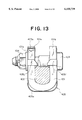
- FIG. 13 is a view of the yoke of FIG. 12, cut away along the line 13--13, seen from the direction of arrow.
- FIG. 14 is a perspective view of a clip of a temporary connection device for a universal joint according to the fifth embodiment of the present invention.
- FIG. 15 is a perspective view of a clip of a temporary connection device for a universal joint according to the sixth embodiment of the present invention.
- FIG. 16 is a perspective view of a clip of a temporary connection device for a universal joint according to the seventh embodiment of the present invention.
- FIG. 17 is a view for showing a yoke to which the clip according to the seventh embodiment is attached, cut away in the same manner as in FIG. 13.
- FIG. 18 is a perspective view of a clip of a temporary connection device for a universal joint according to the eighth embodiment of the present invention.
- FIG. 19 is a side view for showing a universal joint using the yoke to which the clip according to the eighth embodiment is attached, in a state in which the universal joint is attached to a shaft.
- FIG. 20 is a view of the yoke of FIG. 19, seen from the direction 20.
- FIG. 21 is a view of the yoke of FIG. 19, cut away along the line 21--21, seen from the direction of arrow.
- FIG. 22 is a side view for showing a universal joint using the yoke to which the clip of a temporary connection device for a universal joint according to the ninth embodiment is attached, in a state in which the universal joint is attached to a shaft.
- FIG. 23 is a front view of a universal joint according to the tenth embodiment of the present invention.
- FIG. 24 is a cross-sectional view taken along the line 24--24 in FIG. 23 seen from the direction of the arrow.
- FIG. 25 is a cross-sectional view taken along the line 25--25 in FIG. 23 seen from the direction of the arrow.
- FIG. 26 is a view seen from the arrow 26 of FIG. 23.
- FIG. 27 is a view seen from the arrow 27 of FIG. 24.
- FIG. 28 is a front view of a universal joint according to the eleventh embodiment of the present invention.
- FIG. 29 is a back view of the universal joint shown in FIG. 28.
- FIG. 30 is a cross-sectional view taken along the line 30--30 in FIG. 28.
- FIG. 31 is a cross-sectional view of a universal joint according to the twelfth embodiment of the present invention.
- FIG. 32 is a cross-sectional view taken along the line 32--32 in FIG. 31.
- FIG. 33 is a view seen from the arrow 33 of FIG. 31.
- FIG. 34 is a front view of a universal joint according to the thirteenth embodiment of the present invention.
- FIG. 35 is a cross-sectional view taken along the line 35--35 in FIG. 34.
- FIG. 36 is a cross-sectional view taken along the line 36--36 in FIG. 34.
- FIG. 37 is a cross-sectional view taken along the line 37--37 in FIG. 34.
- FIG. 38 is a front view of a universal joint according to the fourteenth embodiment of the present invention.
- FIG. 39 is a front view of a universal joint according to the fifteenth embodiment of the present invention.
- FIG. 40 is a view for showing an arrangement of connection between the yoke and the shaft according to the prior art disclosed in the U.S. Pat. No. 4,900,178.
- FIG. 41 is a cross-sectional view for showing the yoke 11 of FIG. 40, cut away in a direction perpendicular to the axis of the shaft 12.
- FIG. 42 is a cross-sectional view for showing the yoke 11 of FIG. 40, cut away in a direction perpendicular to the axis of the shaft 12.
- FIG. 43 is a view for showing an arrangement of the prior art which is disclosed in the U.S. Pat. No. 5,358,350, and is similar to that shown in FIGS. 41 and 42.
- FIG. 1 is a perspective view for showing a clip of a yoke of a temporary connection device for a universal joint according to the first embodiment.
- FIG. 2 is a side view for showing a universal joint which uses a yoke to which the clip according to the first embodiment is attached, in a state in which the universal joint is attached to the shaft.
- FIG. 3 is a view of the yoke of FIG. 2, cut-away along the line 3--3 and seen from the direction of arrow.
- FIG. 4 is a view of the yoke of FIG. 2, cut-away along the line 4--4 and seen from the direction of arrow.
- FIG. 5 is a view of a bolt of FIG. 5, cut-away along the line 5--5 and seen from the direction of arrow.
- FIG. 6 is a side view of the universal joint according to the present embodiment, on the side opposite to that shown in FIG. 2.
- FIG. 7 is a view for showing the universal joint of FIG. 2 in a state in which the bolt has been removed therefrom.
- FIG. 8 is a view of the yoke in FIG. 7, cut-away along the line 8--8 and seen from the direction of arrow.
- a clip 105 is formed by bending a single thin steel plate by press working. More specifically, the clip 105 has a U-shaped main body 105a. A pair of bolt bores 105b, 105c are formed to pass through the main body 105a from the both sides thereof.
- the bolt bore 105b on the nut side is provided with three protrusions 105d on the inner periphery thereof at equal intervals.
- An installing portion 105e which is U-shaped in cross section is formed on the upper edge of the main body 105a above the bolt bore 105b.
- a pair of trapezoid pieces (projecting portions) 105f, 105g are formed in parallel adjacent to the other bolt bore 105c to be extended substantially perpendicularly from the main body 105a.
- One of the trapezoid pieces 105g is extended from the inner periphery of the bolt bore 105c, while the other trapezoid piece 105f is extended from a side edge of the main body 105a.
- cutouts 105h for mitigating stress concentration and facilitating the bending are formed at the joint between the trapezoid piece 105g and the main body 105a.
- a steering shaft 102 in a steering apparatus of a motor vehicle is fitted in a yoke 101, and this yoke 101 is connected to another yoke 107 through a cross shaft 106.
- the yoke 101 is composed of a fit portion 101e in which the shaft 102 is fitted, and an arm portion 101f to be connected to the cross shaft 106. These parts are formed in one piece by press-working.
- a U-shaped groove which is U-shaped in cross section corresponding to the shape of the shaft 102 is formed with a bottom wall portion 101g and a pair of tabs 1l0a, 101b, as shown in FIGS. 3 and 4. Further, the fit portion 101e is moved and rotated from the lower part when the shaft 102 is normally in a still state, whereby the shaft 102 is inserted into the U-shaped groove of the fit portion 101e.
- the clip 105 is attached in such a manner that the main body 105a thereof winds around the outer periphery of the yoke 101. However, it is arranged that, in the vicinity of the corners of the main body 105a, there are formed spaces between the main body 105a and the outer periphery of the yoke 101, so that the clip 105 is brought into closer contact with the yoke 101 by the elasticity thereof.
- an installing/securing portion 105e of the clip 105 is arranged to wind around the upper end of the tab 110a of the yoke 101, and an extended amount thereof from the upper end toward the lower part is set to be L.
- the nut 104 which is threadably engaged with the bolt 103 is a caulking nut in which a part 104a of a nut screw portion is caulked. With this nut, the threadable engagement with the bolt 103 becomes more secured so that the bolt is prevented from falling off. Then, the nut 104 and the bolt 103 are rotated together to press the shaft 102.
- the trapezoid piece 105f has an slant cam portion 105i which is a part of the arch at the tip end thereof. Though not shown in the drawing, the trapezoid piece 105g has a similar slant surface.
- the bolt 103 is comprised of a head portion 103a, a neck portion 103b, an oval portion 103c, a male screw portion 103d and a tapered portion 103e, which are connected with each other.
- the inner diameter of the bolt bore 101d of the yoke is larger than the outer diameter of the neck portion 103b, and the inner diameter of the bolt bore 101c is slightly larger than the outer diameter of the male screw portion 103d.
- the oval portion 103c of the bolt 103 is oval-shaped in cross section.
- the male screw portion 103d of the bolt 103 is, when inserted into the yoke 101, engaged with the protrusion 105d of the clip 105, so that the bolt 103 is prevented from falling of f or disengaging even when the male screw portion 103d is not threadably engaged with the nut 104 (see FIGS. 3 and 4).
- an inscribed circle of the protrusion 105d is slightly smaller than the outer diameter of the bolt male screw 103d.
- three protrusions 105d are formed on the clip 105 in the first embodiment, it is possible to prevent the bolt 103 from falling off or disengaging if there is one protrusion 105d or more.
- the bolt bore 105c of the clip 105 and the bolt bore 101d of the yoke 101 are slightly shifted. More specifically, the bolt bore 105c of the clip 105 is slightly shifted with respect to the bolt bore 101d of the yoke 101 to the upper right in FIG. 7. As a result, the yoke 101 is in a state of being exposed from the bolt bore 105c in the first quadrant.
- the tabs 101a, 101b of the yoke 101 are not completely parallel to each other, but the yoke 101 is slightly open wider in the upper part thereof.
- An angle ⁇ between the tabs 101a and 101b in the first embodiment is about 2 degrees. Such angle serves to cause the yoke 101 to easily store the shaft 102 even when the installing portion 105e of the clip 105 winds around the upper edge of the tab 101b.
- the shaft 102 is brought into contact with the slant cam surface 105i of the trapezoid pieces 105f, 105g of the clip 105, whereby the trapezoid pieces 105f, 105g are moved in a direction in which they are separated away from the shaft 102, and when the shaft 102 has passed through, the trapezoid pieces 105f, 105g are returned to their original positions by the elasticity of the clip 105.
- the clip 105 is made of a thin plate member and can be easily deformed, so that two trapezoid pieces are provided to secure a stable retaining effect, etc., of the shaft and to prevent the shaft from falling off from the yoke 101.
- the bolt 103 is inserted into the bolt bores 101c, 101d of the yoke 101. As described above, if the protrusions 105d of the clip 105 are retained by the male screw portion 103d of the bolt 103, the bolt 103 becomes resistant to falling off or disengaging.
- the trapezoid pieces 105f, 105g of the clip 105 are pushed out from a space between the tabs after the bolt 103 and the nut 104 are disengaged from each other. In this manner, the removal can be easily carried out.
- the clip since such clip is employed, it becomes easier to temporarily retain the yoke and the shaft or to temporarily retain the yoke and bolt at the time of assembling, whereby the workability can be conspicuously improved. Also, though the ease of assembly is improved, it becomes also easier to separate the shaft from the yoke. Further, since this clip is provided with a pair of trapezoid pieces, the retaining performance of the shaft becomes excellent. In addition, such clip can be manufactured by press working at a comparatively low cost.
- FIG. 9 is a cross-sectional view for showing the clip according to the second embodiment in a state in which it is attached to the yoke. It should be noted that description will be made chiefly on the components and arrangements different from those of the first embodiment shown in FIG. 1, and detailed description will be omitted for those common to the two embodiments.
- the second embodiment shown in FIG. 9 is different from the first embodiment in the shapes of a clip 205 and a nut 204. More specifically, a protrusion 205d which is formed on a bolt bore 205b of the clip 205 is inclined toward the nut 204. A recess 204a is formed on the end surface of the nut 204 corresponding to the inclined protrusion 205d.
- the inclined protrusion 205d is brought into contact with a male screw portion 103d of the bolt 103 to obtain a more satisfactory retaining function.
- the recess 204a of the nut 204 forms a so-called escape for avoiding contact with such protrusion 205d when the nut 204 is fastened up.
- FIG. 10 is a front view of a clip according to the third embodiment of the present invention. Also as to the third embodiment, description will be made chiefly on different components and arrangements from the first embodiment shown in FIG. 1, and detailed description will be omitted for common components.
- the third embodiment shown in FIG. 10 is different from the first embodiment in the positions at which the trapezoid pieces are formed. More specifically, a clip 305 is provided with trapezoid pieces 305f, 305g which extend from the both sides of the inner periphery of a bolt bore 305c.
- a double-dotted chain line shown in FIG. 10 indicates a trapezoid piece after it is punched by a press from a material, but before it is bent.
- the material can be used without waste and the manufacturing cost of the clip can be reduced.
- the length of the trapezoid pieces 305f, 305g can not exceed the radius of the bolt bore 305c, so that the length can not be made very large.
- a yoke to which such clip 305 is attached is required to be comparatively thin.
- FIG. 11 is a perspective view of a clip according to the fourth embodiment of the present invention.
- FIG. 12 is a side view for showing a universal joint to which the clip of FIG. 11 is attached, in a state in which a bolt has been removed.
- FIG. 13 is an elevational cross-sectional view of the yoke of FIG. 12, cut-away along the line 13--13, and seen from the direction of arrow.
- the fourth embodiment shown in FIG. 11 is different from the first embodiment chiefly in the number and the positions of the trapezoid pieces. More specifically, like in the first embodiment, a clip 405 is provided with a pair of trapezoid pieces 405f, 405g adjacent to one of bolt bores 405c, which trapezoid pieces are extended in parallel to each other in a sustantially perpendicular direction from a main body 405a. However, adjacent to a bolt bore 405b on the nut side, another trapezoid piece 405j is also extended substantially perpendicularly from the main body 405a.
- the trapezoid piece 405 has a symmetrical shape with respect to the trapezoid piece 405f, and is extended from a side edge of the main body 405a so as to be opposite to the trapezoid piece 405f. It should be noted that, in this embodiment, as shown in FIGS. 12 and 13, a recess 101e is formed at the center of the upper end of the tab 101a of the yoke 101, and an installing portion 405e is fitted in this recess 101e.
- the shaft 102 can be temporarily retained more securely. That is, the shaft 102 is retained not only by the trapezoid pieces 405f, 405g on the tab 101b side, but also by the trapezoid piece 405j on the tab 101a side, as shown in FIG. 13. As a result, it becomes difficult for the shaft 101 to fall off or disengage when the yoke 101 is caused to carry out the temporary retention. Since the installing portion 405e is fitted in the recess 101e of the tab 101a, there is little possibility for the clip 405 of falling off or removing from the yoke 101 even before the bolt 103 is inserted.
- FIG. 14 is a perspective view of a clip of a temporary connection device for a universal joint according to the fifth embodiment of the present invention. Also as to the fifth embodiment, description will be made chiefly on different components and arrangements from the first embodiment shown in FIG. 1, and detailed description will be omitted for common components.
- the fifth embodiment shown in FIG. 14 is different from the first embodiment chiefly, in the number and the positions of the trapezoid pieces. More specifically a clip 505 is provided with a pair of trapezoid pieces 505f, 505g adjacent to one of bolt bores 505c, which trapezoid pieces are extended in parallel to each other in a substantially perpendicular direction from a main body 505a. Trapezoid piece 505f is extended from the side edge of main body 505a nearest one side of the inner periphery of bolt bore 505c, while trapezoid piece 505g is adjacent the other side of the inner periphery of bolt bore 505.
- the trapezoid piece 505g is extended from the inner periphery of a bolt bore 505c on the left side in FIG. 14 (the side of the cross joint 106), a distance from the trapezoid piece becomes large. Also, like in the fourth embodiment, there is formed another trapezoid piece 505j, adjacent to a bolt bore 505b on the nut side, to extend substantially perpendicular from the main body 505a.
- the operation of the fifth embodiment is substantially the same as that of the fourth embodiment mentioned above.
- a distance between the trapezoid piece 505g and the trapezoid piece 505f is wide, so that an inclination of the shaft 102 with respect to the yoke 101 at the time of temporary retention can be reduced to be small.
- FIG. 15 is a perspective view of a clip of a temporary connection device for a universal joint according to the sixth embodiment of the present invention. Also as to the sixth embodiment, description will be made chiefly on different components and arrangements from the first embodiment shown in FIG. 1, and detailed description will be omitted for common components.
- the sixth embodiment shown in FIG. 15 is different from the first embodiment chiefly in the number and the positions of the trapezoid pieces, like in the fourth and fifth embodiments. More specifically, like in the first embodiment, a clip 605 is provided with a pair of trapezoid pieces 605f, 605g adjacent to one of bolt bores 605c, which trapezoid pieces are extended in parallel to each other in a substantially perpendicular direction from a main body 605a. However, the trapezoid piece 605g is extended from the inner periphery of a bolt bore 605c on the left side in FIG. 15, like in the fifth embodiment. There is also formed a comparatively short rectangular piece 605k which is extended from the inner periphery on the right side (on the shaft 102 side) of the bolt bore 605c, substantially perpendicular from the main body 605a.
- the operation of the sixth embodiment is substantially the same as that of the fifth embodiment mentioned above.
- the tab 101b is sandwiched by and between the rectangular piece 605k and the trapezoid piece 605f when the clip 605 is mounted, so that there is further less possibility for the clip 605 of falling off or disengaging from the yoke 101.
- a similar arrangement to the trapezoid piece (405j) on the tab 101a side in the fourth embodiment may be added to the configuration of the sixth embodiment.
- FIG. 16 is a perspective view of a clip of a temporary connection device for a universal joint according to the seventh embodiment of the present invention.
- FIG. 17 is a view for showing a yoke with the clip of FIG. 16 attached thereto, cut-away in the same manner as in FIG. 13. Also as to the seventh embodiment, description will be made chiefly on different components and arrangements from the first embodiment shown in FIG. 1, and detailed description will be omitted for common components.
- the seventh embodiment shown in FIG. 16 is different from the first embodiment chiefly in the number and the positions of the trapezoid pieces. More specifically, like in the first embodiment, a clip 705 is provided with a pair of trapezoid pieces 705f, 705g adjacent to one of bolt bores 705c, which trapezoid pieces are extended in parallel to each other substantially perpendicular from a main body 705a of the clip 705. Further, like in the fourth embodiment, another trapezoid piece 705j is extended substantially perpendicularly from the main body 705a, adjacent to the bolt bore 705b on the nut side.
- a flange 705m is additionally provided on the lower part of the trapezoid piece 705j in this embodiment, which flange is extended from the side edge of the main body 705a so as to be opposite to the trapezoid piece 705f.
- the clip 705 has a smaller distance t from the outer periphery of the yoke 101 in the vicinity of the corner of the main body 705a, compared with that in any of the foregoing embodiments.
- cutouts 705n are formed on the main body 705a respectively on the both sides of the protrusion 705d formed on the bolt bore 705b, whereby the substantial length of each protrusion 705d becomes large.
- the operation of the seventh embodiment is substantially the same as that of the fourth embodiment mentioned above.
- the flange 705m is additionally provided on the lower part of the trapezoid piece 705j, and the clip 705 has the smaller distance t from the outer periphery of the yoke 101 in the vicinity of the corner of the main body 705a, which effects the following operation. That is, when the nut 104 is fastened up, the main body 705a is bent to be deformed in the directions indicated by the arrows A and B in FIG. 12, due to the accompaniment movement caused by the frictional resistance on the seat surface.
- FIG. 18 is a perspective view of a clip of a temporary connection device for a universal joint according to the eighth embodiment of the present invention.
- FIG. 19 is a side view for showing a universal joint which employs a yoke with the clip according to the eighth embodiment attached thereto, in a state in which the yoke is mounted on the shaft.
- FIG. 20 is a view taken along the line 20--20 in FIG. 19
- FIG. 21 is a cross-sectional view taken along the line 21--21 in FIG. 19. It should be noted that description will be made chiefly on different components and arrangements from the first embodiment shown in FIG. 1, and detailed description will be omitted for common components.
- the eighth embodiment is different from the first embodiment not only in the number and the positions of the trapezoid pieces, but also in that a bolt temporary retaining pawl is provided. More specifically, a clip 805 is provided with one trapezoid piece 805g which is adjacent to one bolt bore 805c to be extended inward substantially perpendicular from the main body 805a of the clip 805, and another trapezoid piece 805j which has the same shape as that in the seventh embodiment and is adjacent to the bolt bore 805b on the nut side to be extended substantially perpendicular from the main body 805a.
- the clip 805 is also provided with a pair of bolt retaining pawls 805o, 805p which are formed at the positions corresponding to the right and left sides of the bolt bore 805c to be extended outward from the side edge of the main body 805a.
- Each of these bolt retaining pawls has a substantially U-shaped form which opens toward the main body 805a, when seen from above, and is inclined in such a manner that a space between latching portions (free end portions) 805q, 805r of the respective pawls becomes narrower inward.
- the tip end portions of the both latching portions 805q, 805r are formed to have a smaller space therebetween than the head portion 103a of the bolt 103.
- a space larger than the thickness of the head portion 103a of the bolt 103 is formed with the main body 805a.
- bolt retaining pawls 805o, 805p are formed on the body 805a to effect the following operation. That is, when the bolt 103 is inserted into the clip 805 and the yoke 101, the head portion 103a of the bolt 103 is brought into contact with the latching portions 805q, 805r of the bolt retaining pawls 805o, 805p, and then, stretches open the both latching portions 805q, 805r, as indicated by the arrows of double-dotted chain line in FIG. 20.
- the head portion 103a of the bolt 103 is disengaged from the tip ends of the latching portions 805q, 805r, whereby the bolt retaining pawls 805o, 805p are returned to their original forms, as indicated by the arrows of solid line.
- the pressing resistance is rapidly decreased, and an assembling worker can confirm without fail the completion of the bolt inserting step.
- the inserted bolt 103 is halted by the latching portions 805q, 805r of the bolt retaining pawls 805o, 805p, so as not to fall off or disengage unexpectedly.
- FIG. 22 is a side view of a yoke with a clip according to the ninth embodiment attached thereto, in which the head portion of the bolt is indicated by a double-dotted chain line for the convenience of description. It should be noted that the configuration of the ninth embodiment is arranged by partly varying the configuration of the eight embodiment which is shown in FIGS. 18 to 21, and detailed description will be omitted for common components.
- the ninth embodiment is different from the eighth embodiment in that one of the paired bolt bores 101d of the yoke 101 and that 905c of the clip 905 are laterally elongated, whereby the contact area between the head portion 103a of the bolt 103 and the seat surface becomes large. As a result, it is possible to prevent the bolt 103 from being loosened, so as to obtain a stable shaft :-retaining performance.
- FIG. 23 is a front view of a temporary connection device for a universal joint according to the tenth embodiment of the present invention.
- FIG. 24 is a cross-sectional view taken along the line 24--24 in FIG. 23.
- FIG. 25 is a cross-sectional view taken along the line 25--25 in FIG. 23.
- FIG. 26 is a view seen from the arrow 26 in FIG. 23.
- FIG. 27 is a view seen from the arrow 27 in FIG. 24.
- a steering shaft B1 in a steering apparatus of a motor vehicle is fitted in a yoke B2, and this yoke B2 is connected to another yoke B4 through a cross shaft B3.
- the yoke B2 is composed of a fit portion B5 in which the shaft B1 is fitted, and an arm portion B6 to be connected to the cross shaft B3. These parts are formed in one piece by press-working.
- This fit portion B5 is provided with a U-shaped groove having a U-shaped cross section which is corresponding to the shape of the shaft B1 by use of a pair of tabs B7, B8, as shown in FIGS. 24 and 25. Further, the shaft B1 is normally in a stationary state, and the fit portion B5 is moved and rotated from the lower part, so that the shaft B1 is inserted into the U-shaped groove B9 of the fit portion B5.
- a clip B10 is attached to this fit portion B5 in advance.
- This clip B10 has the main body B11 having a U-shaped cross section which is engaged with the lower side of the fit portion B5.
- a pair of protruding pieces which are capable of elastic deformation are extended toward the U-shaped groove B9 through the thicker-part surface of the pair of tabs B7, B8 from this main body B11.
- These protruding pieces B12, B13 are respectively provided with slant cam surfaces B12a, B13a on the upper sides thereof, as well as flat planes B12b, B13b formed parallel to each other on the flat upper surface of the shaft B1 on the lower side thereof.
- the protruding pieces B12 and B13 cause the slant surfaces B12a, B13a to be engaged with the shaft B1 and retracted, and are returned to their original positions by the elasticity thereof after the shaft B1 is completely stored in the U-shaped groove B9.
- the shaft B1 is temporarily retained in the U-shaped groove B9 by use of the flat surfaces B12b, B13b on the lower side so as to prevent the shaft B1 from falling off or disengaging.
- the U shape of the main body B11 of the clip B10 has an angle of 1 degree to 15 degrees in total in a direction which becomes an interference, with respect to the U shape on the outer surface of the yoke B2, whereby the clip B10 can be retained without backlash with respect to the yoke B2.
- a band portion B14 is extended upward along the thicker-part surface of one of the tabs B8.
- This band portion B14 is extended to go over the apex of the tab B8 up to a portion inclined downward.
- a pair of sandwich pieces B15a, B15b are provided for sandwiching the thicker-part surface of the tab B8 therebetween at the tip ends of this band portion B14.
- the clip B10 is supported in the fit portion B5 of the yoke B2 by these sandwich pieces B15a, B15b.
- the main body B11 of the clip B10 is extended to go above the tab B7, on the tab B7 side.
- This main body B11 is provided with an escape bore B16 for avoiding an interference with a nut B19 as to be described later.
- the clip B10 When the clip B10 thus arranged is attached to the fit portion B5 of the yoke B2, the clip B10 is inserted into the yoke B2 from the direction indicated by the arrow in FIG. 23 until the escape bore B16 of the clip BIO reaches the position of the nut B19.
- the band portion B14 of the clip B10 is wound up from the apex of the tab B8 to the portion inclined downward, so that the thicker-part surface of the tab B8 is sandwiched by and between the pair of sandwich pieces B15a, B15b.
- the clip B10 is comprised of the main body B131, the pair of protruding pieces B12, B13, the band portion 1314, the pair of sandwich pieces B15a, B15b, and the escape bore B16, so that the clip B10 is securely attached to the fit portion B15 of the yoke B2.
- a pair of bolt bores B17 1 , B18 are formed on the pair of tabs B7, B8, respectively.
- the nut B19 is press fitted and secured to one of the bolt bores B17 in advance.
- a bolt B20 which has a tapered collar B21 made of resin is inserted into the other bolt bore B18 and is fastened up by the nut B19 as to be described later.
- the shaft B1 is centered by the tapered collar B21.
- the yoke B2 is formed by press-working, so that the yoke B2 does not take an exact U shape corresponding to the outer form of the shaft B1, but spreads out.
- the shaft B1 when the shaft B1 is inserted into the U-shaped groove B9, the shaft B1 does not interfere with the pair of sandwich pieces B15a, B15b and can be easily inserted.
- the U-shaped groove B9 of the yoke B1 is opened upward by, for example, about 2 degrees, which also facilitates the insertion of the shaft B1 into the U-shaped groove B9.
- the shaft B1 in a stationary state is inserted into the U-shaped groove B9 of the fit portion B5 of the yoke B2 to be fitted therein.
- the bolt B20 having the tapered collar B21 is passed through the bolt bore B18 of the tab B8 and the bolt bore B17 of the tab B7, so as to be engaged with the nut B19 which has been press fitted and secured to the bolt bore B17 in advance, and fastened up.
- the tapered collar B21 is brought into contact with the shaft B1 and urges the shaft B1 toward the lower side of the U-shaped groove B9, whereby the centering of the shaft Bl for the U-shaped groove B9 is carried out.
- the clip B10 is attached to the tab B8 of the yoke B2 with the pair of sandwich pieces B15a, B15b, so that there is no possibility for the clip B10 of falling off or disengaging unexpectedly.
- the clip B10 is attached to the yoke B2 by use of the pair of sandwich pieces B15a, B15b, the clip B10 can be easily removed and reused even after fastened by the bolt and the nut. Also, the present embodiment can be applied to a case in which the yoke B2 is short.
- FIG. 28 is a front view of a universal joint according to the eleventh embodiment of the present invention.
- FIG. 29 is a back view of the universal joint shown in FIG. 28.
- FIG. 30 is a cross-sectional view taken along the line 30--30 in FIG. 28. It should be noted that the identical components to those in the tenth embodiment are given the same referential numerals, and description thereof will be omitted.
- the band portion B14 is not extended from the apex of the tab B8 to the portion inclined downward, but halted at the apex of the tab B8, and the pair of sandwich pieces B15a, B15b sandwich this apex of the tab B8 therebetween.
- the clip B10 can be manufactured easily, compared with the tenth embodiment.
- the escape bore B16 of the clip B10 is formed around the nut B19.
- three protrusions B23 are formed on the circumference of the bore B22 of the clip B10 formed around the nut B19. Accordingly, when the clip B10 is attached to the yoke B2, these three protrusions B23 are raised to be engaged with the circumference of the nut B19, whereby the clip B10 can be retained on the yoke B2 securely.
- the tenth embodiment there are provided one pair of protruding pieces B12, B13 in order to temporarily retain the shaft B1.
- the eleventh embodiment as shown in FIG. 30, there is not provided the protruding piece B12 on the tab B7 side, but only the protruding piece B13 is provided on the tab B8 side, whereby the shaft B1 is temporarily retained by this protruding piece B13.
- FIG. 31 is a cross-sectional view of a universal joint according to the twelfth embodiment of the present invention.
- FIG. 32 is a cross-sectional view taken along the line 32--32 in FIG. 31.
- FIG. 33 is a view seen from the left side in FIG. 31. It should be noted that the identical components to those in the tenth embodiment are given the same referential numerals in this embodiment, and description thereof will be omitted.
- the band portion B24 is extended from the apex of the tab B7 to the portion inclined downward, also on the tab B7 side.
- a pair of sandwich pieces B25a, B25b for sandwiching the tab B7 therebetween are provided at the tip end of this band portion B24. Accordingly, the clip B10 is securely retained on the yoke B2 not only by the pair of sandwich pieces B15a, B15b on the tab B8 side, but also by the pair of sandwich pieces B25a, B25b on the tab B7 side.
- a cam bolt B26 having a cam portion B27 and a caulking nut B28 are also employed.
- the cam portion B27 takes an oval shape, as shown in FIG. 32.
- FIG. 34 is a front view of a connection device for a universal joint according to the thirteenth embodiment of the present invention.
- FIG. 35 is a cross-sectional view taken along the line 35--35 in FIG. 34.
- FIG. 36 is a cross-sectional view taken along the line 36--36 in FIG. 34.
- FIG. 37 is a cross-sectional view taken along the line 37--37 in FIG. 34.
- a steering shaft C1 in a steering apparatus of a motor vehicle has a substantially oval or egg-shaped cross section with a notch C1a and is fitted in a yoke C2, and this yoke C2 is connected to another yoke C4 through a cross shaft C3.
- the yoke C2 is composed of a fit portion C5 in which the shaft C1 is fitted, and an arm portion C6 to be connected to the cross shaft C3. These parts are formed in one piece by press-working.
- This fit portion C5 is provided with a U-shaped groove C9 having a U-shaped cross section which is corresponding to the shape of the shaft C1 with a pair of tabs C7, C8, as shown in FIGS. 35 and 36. Further, the shaft C1 is moved and rotated from above and is inserted into the U-shaped groove C9 to be fitted.
- One of the tabs C7 is provided with a nut bore C10, as shown in FIG. 36, and a nut C11 is press fitted and secured to this nut bore C10.
- the nut C11 has a knurling C12 which has the diameter slightly larger than the nut bore C10, and a small-diameter portion having the diameter slightly smaller than the nut bore C0 and a tapered groove having the diameter which becomes larger toward the knurling at the tip end thereof.
- a bolt bore C14 is formed on one of the tabs C8, and a bolt C15 having a tapered collar C16 made of resin is inserted into this bolt bore C14. Then, as to be described later, the bolt C15 is fastened by the nut C11 and the shaft C1 is centered by the tapered collar C16.
- a clip C20 which is formed of an elastically deformable thin plate is attached to the outer wall surface of the tab C7 in advance.
- the main body C20a of this clip C20 has an installing bore C21 which is larger than the outer diameter of the knurling C12 of the nut C11. Further, the clip main body C20a is provided with a bent leg portion C22 at the upper part thereof, a bent leg portion C23 at an diagonally upper part thereof, and a bent leg portion C24 at the lower part thereof, respectively.
- the clip main body C20a is provided with an elastically deformable bent piece C25 which is bent on the thicker-part surface of the tab C7 and is extended in parallel to the thicker-part surface.
- a protruding piece C26 having a triangular shape is formed at the upper end of this bent piece C25.
- This protruding piece C26 is provided with a slant cam surface C26a on the upper side thereof, and a flat surface C26b which is formed in parallel to the flat upper surface of the shaft C1 on the lower side thereof.
- the protruding piece C26 is returned to its original position by the elasticity thereof, temporarily retains the shaft C1 in the U-shaped groove C9 with the lower flat surface C26b, and prevents the shaft C1 from falling off or disengaging.
- a distance dl between the peripheral edge of the installing bore C2 of the clip main body C20a and the starting point of a curve R of the bent portion of the bent piece C25 is set to be comparatively large, so that when the shaft C1 is inserted into the U-shaped groove C9, the bent piece C25 and the protruding piece C26 can be bent by a small load, and the shaft C1 is allowed to pass with a small load.
- This distance d1 is preferably 5 mm or more.
- an inserting power of the shaft C1 is about 15 to 80 N.
- the clip main body C20a is attached to the outer wall surface of the tab C7 in advance.
- Leg portions C22, C23, C24 of the clip main body C20a and the protruding piece C26 are respectively engaged with the tab C7, so that the clip main body C20a is positioned on the outer wall surface of the tab C7.
- the nut C11 is inserted into the nut bore C10 through the installing bore C21 of the clip main body C20a, and the nut C11 is urged into the nut bore CIO in such a manner that the inner peripheral surface of the nut bore C10 is cut into the tapered groove C13, whereby the clip main body C20a is fixed on the outer wall surface of the tab C7.
- the shaft C1 is moved and rotated from diagonally above so as to be inserted into the U-shaped groove of the yoke C2 to which the clip C10 is attached In advance.
- the protruding piece C26 When this shaft C1 is to be inserted into the U-shaped groove C9, the protruding piece C26 causes the slant surface C26a to be engaged with the shaft C1 and is retracted. After the shaft C1 is completely stored in the U-shaped groove C9, the protruding piece C26 is returned to its original position by the elasticity thereof, temporarily retains the shaft C1 in the U-shaped groove C9 with the lower flat plane C26b, and prevents the shaft C1 from falling off or disengaging.
- the bolt C15 having the tapered collar C16 is passed through the bolt bore C14 of the tab C8, so as to be engaged with the nut C11 which is urged into the nut bore C14 in advance, and fastened up.
- the tapered collar C16 is brought into contact with the shaft C1 to urge the shaft C1 toward the lower part of the U-shaped groove C9, whereby the shaft C1 is centered with respect to the U-shaped groove C9.
- the clip C20 is fixed to the outer wall surface of the tab C7 with the nut C11 which is urged into the nut bore C10. As a result, there is no chance for the clip of falling off or disengaging unexpectedly.
- the shaft C1 can be temporarily retained on the yoke C2 securely due to the elastic deformation of the protruding piece C26 of the clip C20, whereby the workability can be conspicuously enhanced.
- the manufacturing cost can be reduced.
- a working space for connecting the shaft 1 is small, the invention can be applied even to a steering shaft of a motor vehicle having a small working space.
- FIG. 38 is a front view of a connection device for a universal joint according to the fourteenth embodiment of the present invention.
- the nut C11 is urged into the nut bore in the same manner as in the twelfth embodiment, and three projections C32 are formed on the circumference of the bore C31 of the clip main body C20a formed around the nut C11. Accordingly, when the clip main body C20a is attached to the outer wall surface of the tab C7, it is possible to securely fix the clip main body C20a to the outer wall surface of the tab C7, by causing these three projections C32 to be engaged with the circumference of the nut C11.
- the thickness of the clip main body C20a is set to be 0.5 mm in the twelfth embodiment, the thickness of the clip main body C20a is set to be 0.7 mm in the present embodiment.
- leg portions C23, C24 of the thirteenth embodiment are not provided.
- FIG. 39 is a front view of a universal joint according to the fifteenth embodiment of the present invention.
- a nut C43 urged into a nut bore takes a square shape
- a bore C42 of the clip main body C20 is formed in the surroundings of this square nut C43
- four projections C43 are formed to be engaged with the respective sides of this square nut C43.
- the clip main body C20a Since the four projections C43 of the clip main body C20a are respectively engaged with the four sides of the square nut C43 as described above, the clip main body C20a can be securely fixed to the square nut C43. For this reason, when the shaft C1 is temporarily retained by the clip main body C20a, the rotation of the clip main body C20a can be securely prevented, so as to temporarily retain the shaft 1 securely.
- the nut C41 takes a square form, it is required to install the nut on the outer wall surface of the tab 7 by positioning.
- the leg portions C22, C23, C24 in the twelfth embodiment are not provided in the fifteenth embodiment.
- the clip does not easily fall off or disengage from the yoke due to the nut fixed in the nut bore of the tab, or because the clip main body is mounted on this nut.
Landscapes
- Engineering & Computer Science (AREA)
- General Engineering & Computer Science (AREA)
- Mechanical Engineering (AREA)
- Chemical & Material Sciences (AREA)
- Combustion & Propulsion (AREA)
- Transportation (AREA)
- Clamps And Clips (AREA)
Applications Claiming Priority (10)
| Application Number | Priority Date | Filing Date | Title |
|---|---|---|---|
| JP9-190727 | 1997-07-02 | ||
| JP19072797 | 1997-07-02 | ||
| JP9-333747 | 1997-11-19 | ||
| JP9333747A JPH11153148A (ja) | 1997-11-19 | 1997-11-19 | 自在継手 |
| JP9-354083 | 1997-12-09 | ||
| JP35408397 | 1997-12-09 | ||
| JP9-363288 | 1997-12-16 | ||
| JP9363288A JPH11182564A (ja) | 1997-12-16 | 1997-12-16 | 自在継手 |
| JP3033198 | 1998-01-29 | ||
| JP10-030331 | 1998-01-29 |
Publications (1)
| Publication Number | Publication Date |
|---|---|
| US6155739A true US6155739A (en) | 2000-12-05 |
Family
ID=27521213
Family Applications (1)
| Application Number | Title | Priority Date | Filing Date |
|---|---|---|---|
| US09/100,875 Expired - Lifetime US6155739A (en) | 1997-07-02 | 1998-06-22 | Temporary connection device for universal joint |
Country Status (2)
| Country | Link |
|---|---|
| US (1) | US6155739A (de) |
| DE (1) | DE19829304B4 (de) |
Cited By (22)
| Publication number | Priority date | Publication date | Assignee | Title |
|---|---|---|---|---|
| US6443650B2 (en) * | 2000-02-03 | 2002-09-03 | Nsk Ltd. | Connection structure of lateral insert type yoke and shaft |
| GB2374382A (en) * | 2001-02-26 | 2002-10-16 | Torrington Co | Steering shaft retaining clip |
| US6474898B1 (en) * | 1999-04-27 | 2002-11-05 | Koyo Seiko Co., Ltd. | Coupling structure between shaft and yoke |
| US6575658B2 (en) * | 2001-03-14 | 2003-06-10 | Nacam France Sa | Assembling a steering column bracket with a steering gear of an automobile vehicle |
| US6739790B1 (en) * | 2002-12-13 | 2004-05-25 | The Torrington Company | Shaft assembly safety mechanism |
| US20040156670A1 (en) * | 2003-01-29 | 2004-08-12 | Koyo Seiko Co., Ltd. | Coupling structure of shaft body and shaft joint |
| US20040185947A1 (en) * | 2003-03-17 | 2004-09-23 | Koyo Seiko Co., Ltd. | Coupling structure of shaft body and shaft joint |
| US20050169697A1 (en) * | 2004-02-03 | 2005-08-04 | Timken Us Corporation | Adjustable shaft connector |
| US6942415B2 (en) | 2002-02-26 | 2005-09-13 | The Torrington Company | Shaft assembly safety mechanism |
| US20060034650A1 (en) * | 2003-01-08 | 2006-02-16 | Michael Appleyard | Connection between components |
| US20060045612A1 (en) * | 2004-09-01 | 2006-03-02 | Nsk Ltd. | Joint section between shaft and universal joint yoke |
| US20060045611A1 (en) * | 2004-08-24 | 2006-03-02 | Castellon Melchor D | Mounting assembly for drive shafts in universal joint yokes |
| US20070046092A1 (en) * | 2005-06-30 | 2007-03-01 | Intier Automotive Inc. | Structural fastening variable slip bushing |
| EP1840398A1 (de) * | 2006-03-30 | 2007-10-03 | JTEKT Corporation | Kardangelenk |
| US20090016812A1 (en) * | 2005-12-29 | 2009-01-15 | Paul Hettich Gmbh & Co. Kg | Quick-fixing element |
| US20110123260A1 (en) * | 2008-07-30 | 2011-05-26 | Paul Hettich Gmbh & Co. Kg | Quick-action fastening element |
| US20130064603A1 (en) * | 2011-09-13 | 2013-03-14 | Steering Solutions Ip Holding Corporation | Intermediate shaft connection assurance device |
| US20130336712A1 (en) * | 2012-06-19 | 2013-12-19 | GM Global Technology Operations LLC | Fully engaged joint assembly |
| US20140356062A1 (en) * | 2013-05-29 | 2014-12-04 | Zf Systemes De Direction Nacam S.A.S | Securitized assembly of two pieces via screwing process |
| US20150037093A1 (en) * | 2013-08-05 | 2015-02-05 | GM Global Technology Operations LLC | Coupling element with non-regular shaft interface |
| US9545942B2 (en) * | 2014-07-16 | 2017-01-17 | Steering Solutions Ip Holding Corporation | Assembly detection means |
| US9663133B2 (en) | 2013-02-15 | 2017-05-30 | Steering Solutions Ip Holding Corporation | Intermediate shaft for steering column with bearing and lock sleeve |
Families Citing this family (6)
| Publication number | Priority date | Publication date | Assignee | Title |
|---|---|---|---|---|
| US6350078B1 (en) * | 1999-09-24 | 2002-02-26 | The Torrington Company | Shaft depressor for a slap yoke in a steering assembly |
| FR2802590B1 (fr) * | 1999-12-16 | 2002-07-19 | Delphi Tech Inc | Dispositif de reception d'une vis de serrage notamment d'une machoire de joint de cardan sur un arbre de direction de colonne de direction |
| JP2006097884A (ja) * | 2004-08-30 | 2006-04-13 | Nsk Ltd | シャフトと自在継手のヨークとの結合部 |
| DE102005033627A1 (de) * | 2005-07-19 | 2007-01-25 | GM Global Technology Operations, Inc., Detroit | Vorrichtung zur Verbindung einer Zwischenwelle mit einem Ritzel eines Lenkgetriebes |
| US8235420B2 (en) * | 2007-04-27 | 2012-08-07 | Nsk Ltd. | Steering apparatus, manufacturing method of steering apparatus and manufacturing method of shaft |
| US8328648B2 (en) * | 2010-11-23 | 2012-12-11 | Steering Solutions Ip Holding Corporation | Cardan joint assembly and a cardan joint protector device |
Citations (7)
| Publication number | Priority date | Publication date | Assignee | Title |
|---|---|---|---|---|
| US4009504A (en) * | 1975-04-15 | 1977-03-01 | Arman D | Support of the wiper blades in the windshield wiper installations on motor vehicles in general |
| JPH0235222A (ja) * | 1987-12-31 | 1990-02-05 | Nacam | 迅速連結装置 |
| US5253949A (en) * | 1992-07-21 | 1993-10-19 | Trw Inc. | Fail-safe universal joint connection |
| US5358350A (en) * | 1992-01-31 | 1994-10-25 | Etablissement Supervis | Connection device for a steering column of a motor vehicle |
| JPH08326767A (ja) * | 1995-05-26 | 1996-12-10 | Nippon Seiko Kk | シャフトと自在継手のヨークとの結合部 |
| JPH08338440A (ja) * | 1995-06-12 | 1996-12-24 | Nippon Seiko Kk | シャフトと自在継手のヨークとの結合部 |
| EP0774399A1 (de) * | 1995-11-20 | 1997-05-21 | Ecia - Equipements Et Composants Pour L'industrie Automobile | System zum Halten der Position eines Klemmelements |
-
1998
- 1998-06-22 US US09/100,875 patent/US6155739A/en not_active Expired - Lifetime
- 1998-06-30 DE DE19829304A patent/DE19829304B4/de not_active Expired - Fee Related
Patent Citations (8)
| Publication number | Priority date | Publication date | Assignee | Title |
|---|---|---|---|---|
| US4009504A (en) * | 1975-04-15 | 1977-03-01 | Arman D | Support of the wiper blades in the windshield wiper installations on motor vehicles in general |
| JPH0235222A (ja) * | 1987-12-31 | 1990-02-05 | Nacam | 迅速連結装置 |
| US4900178A (en) * | 1987-12-31 | 1990-02-13 | Nacam | Coupling device and the application thereof in particular in an automobile steering device |
| US5358350A (en) * | 1992-01-31 | 1994-10-25 | Etablissement Supervis | Connection device for a steering column of a motor vehicle |
| US5253949A (en) * | 1992-07-21 | 1993-10-19 | Trw Inc. | Fail-safe universal joint connection |
| JPH08326767A (ja) * | 1995-05-26 | 1996-12-10 | Nippon Seiko Kk | シャフトと自在継手のヨークとの結合部 |
| JPH08338440A (ja) * | 1995-06-12 | 1996-12-24 | Nippon Seiko Kk | シャフトと自在継手のヨークとの結合部 |
| EP0774399A1 (de) * | 1995-11-20 | 1997-05-21 | Ecia - Equipements Et Composants Pour L'industrie Automobile | System zum Halten der Position eines Klemmelements |
Cited By (38)
| Publication number | Priority date | Publication date | Assignee | Title |
|---|---|---|---|---|
| US6474898B1 (en) * | 1999-04-27 | 2002-11-05 | Koyo Seiko Co., Ltd. | Coupling structure between shaft and yoke |
| US6443650B2 (en) * | 2000-02-03 | 2002-09-03 | Nsk Ltd. | Connection structure of lateral insert type yoke and shaft |
| GB2374382A (en) * | 2001-02-26 | 2002-10-16 | Torrington Co | Steering shaft retaining clip |
| US6692177B2 (en) | 2001-02-26 | 2004-02-17 | The Torrington Company | Steering shaft retaining clip |
| GB2374382B (en) * | 2001-02-26 | 2004-06-30 | Torrington Co | Steering shaft retaining clip |
| US6575658B2 (en) * | 2001-03-14 | 2003-06-10 | Nacam France Sa | Assembling a steering column bracket with a steering gear of an automobile vehicle |
| US6942415B2 (en) | 2002-02-26 | 2005-09-13 | The Torrington Company | Shaft assembly safety mechanism |
| US6739790B1 (en) * | 2002-12-13 | 2004-05-25 | The Torrington Company | Shaft assembly safety mechanism |
| US7318687B2 (en) * | 2003-01-08 | 2008-01-15 | Trw Lucasvarity Electric Steering Limited | Connection between components |
| US20060034650A1 (en) * | 2003-01-08 | 2006-02-16 | Michael Appleyard | Connection between components |
| US7241068B2 (en) * | 2003-01-29 | 2007-07-10 | Jtekt Corporation | Coupling structure of shaft body and shaft joint |
| US20040156670A1 (en) * | 2003-01-29 | 2004-08-12 | Koyo Seiko Co., Ltd. | Coupling structure of shaft body and shaft joint |
| CN101666357B (zh) * | 2003-03-17 | 2013-06-19 | 株式会社捷太格特 | 轴体和联轴节的联接结构 |
| US7488134B2 (en) * | 2003-03-17 | 2009-02-10 | Jtekt Corporation | Coupling structure of shaft body and shaft joint |
| US20040185947A1 (en) * | 2003-03-17 | 2004-09-23 | Koyo Seiko Co., Ltd. | Coupling structure of shaft body and shaft joint |
| US20050169697A1 (en) * | 2004-02-03 | 2005-08-04 | Timken Us Corporation | Adjustable shaft connector |
| US20060045611A1 (en) * | 2004-08-24 | 2006-03-02 | Castellon Melchor D | Mounting assembly for drive shafts in universal joint yokes |
| US7604428B2 (en) * | 2004-08-24 | 2009-10-20 | Melchor Daumal Castellon | Mounting assembly for drive shafts in universal joint yokes |
| US20060045612A1 (en) * | 2004-09-01 | 2006-03-02 | Nsk Ltd. | Joint section between shaft and universal joint yoke |
| US20070046092A1 (en) * | 2005-06-30 | 2007-03-01 | Intier Automotive Inc. | Structural fastening variable slip bushing |
| US7347478B2 (en) * | 2005-06-30 | 2008-03-25 | Intier Automotive Inc. | Structural fastening variable slip bushing |
| US8162560B2 (en) * | 2005-12-29 | 2012-04-24 | Paul Hettich Gmbh & Co. Kg. | Quick-fixing element |
| US20090016812A1 (en) * | 2005-12-29 | 2009-01-15 | Paul Hettich Gmbh & Co. Kg | Quick-fixing element |
| US20070237571A1 (en) * | 2006-03-30 | 2007-10-11 | Jtekt Corporation | Universal joint |
| EP1840398A1 (de) * | 2006-03-30 | 2007-10-03 | JTEKT Corporation | Kardangelenk |
| US7513709B2 (en) | 2006-03-30 | 2009-04-07 | Jtekt Corporation | Universal joint |
| US20110123260A1 (en) * | 2008-07-30 | 2011-05-26 | Paul Hettich Gmbh & Co. Kg | Quick-action fastening element |
| US9205859B2 (en) * | 2011-09-13 | 2015-12-08 | Steering Solutions Ip Holding Corporation | Intermediate shaft connection assurance device |
| US20130064603A1 (en) * | 2011-09-13 | 2013-03-14 | Steering Solutions Ip Holding Corporation | Intermediate shaft connection assurance device |
| US20130336712A1 (en) * | 2012-06-19 | 2013-12-19 | GM Global Technology Operations LLC | Fully engaged joint assembly |
| US9290198B2 (en) * | 2012-06-19 | 2016-03-22 | GM Global Technology Operations LLC | Fully engaged joint assembly |
| US9663133B2 (en) | 2013-02-15 | 2017-05-30 | Steering Solutions Ip Holding Corporation | Intermediate shaft for steering column with bearing and lock sleeve |
| CN104214173A (zh) * | 2013-05-29 | 2014-12-17 | 采埃孚转向机系统纳凯姆联合股份公司 | 紧固装置 |
| CN104214173B (zh) * | 2013-05-29 | 2016-09-14 | 采埃孚转向机系统纳凯姆联合股份公司 | 紧固装置 |
| US20140356062A1 (en) * | 2013-05-29 | 2014-12-04 | Zf Systemes De Direction Nacam S.A.S | Securitized assembly of two pieces via screwing process |
| US20150037093A1 (en) * | 2013-08-05 | 2015-02-05 | GM Global Technology Operations LLC | Coupling element with non-regular shaft interface |
| US9581205B2 (en) * | 2013-08-05 | 2017-02-28 | GM Global Technology Operations LLC | Coupling element with non-regular shaft interface |
| US9545942B2 (en) * | 2014-07-16 | 2017-01-17 | Steering Solutions Ip Holding Corporation | Assembly detection means |
Also Published As
| Publication number | Publication date |
|---|---|
| DE19829304B4 (de) | 2004-12-09 |
| DE19829304A1 (de) | 1999-02-04 |
Similar Documents
| Publication | Publication Date | Title |
|---|---|---|
| US7370878B2 (en) | Structure for attaching a fabric sheet to a vehicle body | |
| JP5170520B2 (ja) | 誤組付防止具およびこれを含む自在継手 | |
| US20010012470A1 (en) | Connection structure of lateral insert type yoke and shaft | |
| US5797696A (en) | Snap connection system | |
| CN114198374A (zh) | 用于连接至少两个特别是板状的元件的连接系统;包括这种连接系统的组件 | |
| EP1117152A2 (de) | Anschlussklemme für Batterie | |
| US6692177B2 (en) | Steering shaft retaining clip | |
| JP7356588B2 (ja) | ルーフマウントアンテナ取付構造 | |
| US12241572B2 (en) | Holder for long member | |
| JP3843610B2 (ja) | ヨークのクリップ | |
| EP0195274A1 (de) | Kupplungsdeckel | |
| JP2009144789A (ja) | クリップナット | |
| JP2005076646A (ja) | 取付クリップ | |
| JP2008180258A (ja) | 薄板ナット | |
| JPH11280725A (ja) | 抜け止めクリップ | |
| JP3106281B2 (ja) | 回り止め付き組合せ端子 | |
| JP3452858B2 (ja) | 接続用端子の取付構造 | |
| JP3037053U (ja) | リベットとその締結構造 | |
| JP2005133790A (ja) | シャフトと自在継手のヨークの結合構造 | |
| JP2008128391A (ja) | スタッド固定クリップ | |
| JP2577997Y2 (ja) | パネル等の取付け用クリップ | |
| JP2594112Y2 (ja) | コントロールケーブルの保持構造 | |
| JPS616015A (ja) | 作動伝達用ケ−ブル固定装置のクランプ脱落防止構造 | |
| JPH08178133A (ja) | ベルトクリップ | |
| WO2025100304A1 (ja) | 留め具 |
Legal Events
| Date | Code | Title | Description |
|---|---|---|---|
| AS | Assignment |
Owner name: NSK LTD., JAPAN Free format text: ASSIGNMENT OF ASSIGNORS INTEREST;ASSIGNORS:SEKINE, HIROSHI;KOMORI, HIROMICHI;REEL/FRAME:009284/0081 Effective date: 19980616 |
|
| STCF | Information on status: patent grant |
Free format text: PATENTED CASE |
|
| FEPP | Fee payment procedure |
Free format text: PAYOR NUMBER ASSIGNED (ORIGINAL EVENT CODE: ASPN); ENTITY STATUS OF PATENT OWNER: LARGE ENTITY |
|
| FPAY | Fee payment |
Year of fee payment: 4 |
|
| FPAY | Fee payment |
Year of fee payment: 8 |
|
| FPAY | Fee payment |
Year of fee payment: 12 |