US6186848B1 - Disassembling method of electronic appliance and disassembling apparatus thereof - Google Patents
Disassembling method of electronic appliance and disassembling apparatus thereof Download PDFInfo
- Publication number
- US6186848B1 US6186848B1 US08/896,015 US89601597A US6186848B1 US 6186848 B1 US6186848 B1 US 6186848B1 US 89601597 A US89601597 A US 89601597A US 6186848 B1 US6186848 B1 US 6186848B1
- Authority
- US
- United States
- Prior art keywords
- cathode
- electronic appliance
- ray tube
- disassembling
- housing
- Prior art date
- Legal status (The legal status is an assumption and is not a legal conclusion. Google has not performed a legal analysis and makes no representation as to the accuracy of the status listed.)
- Expired - Fee Related
Links
Images


Classifications
-
- B—PERFORMING OPERATIONS; TRANSPORTING
- B29—WORKING OF PLASTICS; WORKING OF SUBSTANCES IN A PLASTIC STATE IN GENERAL
- B29B—PREPARATION OR PRETREATMENT OF THE MATERIAL TO BE SHAPED; MAKING GRANULES OR PREFORMS; RECOVERY OF PLASTICS OR OTHER CONSTITUENTS OF WASTE MATERIAL CONTAINING PLASTICS
- B29B17/00—Recovery of plastics or other constituents of waste material containing plastics
- B29B17/02—Separating plastics from other materials
-
- B—PERFORMING OPERATIONS; TRANSPORTING
- B03—SEPARATION OF SOLID MATERIALS USING LIQUIDS OR USING PNEUMATIC TABLES OR JIGS; MAGNETIC OR ELECTROSTATIC SEPARATION OF SOLID MATERIALS FROM SOLID MATERIALS OR FLUIDS; SEPARATION BY HIGH-VOLTAGE ELECTRIC FIELDS
- B03B—SEPARATING SOLID MATERIALS USING LIQUIDS OR USING PNEUMATIC TABLES OR JIGS
- B03B9/00—General arrangement of separating plant, e.g. flow sheets
- B03B9/06—General arrangement of separating plant, e.g. flow sheets specially adapted for refuse
- B03B9/061—General arrangement of separating plant, e.g. flow sheets specially adapted for refuse the refuse being industrial
- B03B9/062—General arrangement of separating plant, e.g. flow sheets specially adapted for refuse the refuse being industrial the refuse being glass
-
- B—PERFORMING OPERATIONS; TRANSPORTING
- B08—CLEANING
- B08B—CLEANING IN GENERAL; PREVENTION OF FOULING IN GENERAL
- B08B5/00—Cleaning by methods involving the use of air flow or gas flow
- B08B5/02—Cleaning by the force of jets, e.g. blowing-out cavities
-
- B—PERFORMING OPERATIONS; TRANSPORTING
- B09—DISPOSAL OF SOLID WASTE; RECLAMATION OF CONTAMINATED SOIL
- B09B—DISPOSAL OF SOLID WASTE NOT OTHERWISE PROVIDED FOR
- B09B3/00—Destroying solid waste or transforming solid waste into something useful or harmless
- B09B3/30—Destroying solid waste or transforming solid waste into something useful or harmless involving mechanical treatment
- B09B3/32—Compressing or compacting
-
- B—PERFORMING OPERATIONS; TRANSPORTING
- B09—DISPOSAL OF SOLID WASTE; RECLAMATION OF CONTAMINATED SOIL
- B09B—DISPOSAL OF SOLID WASTE NOT OTHERWISE PROVIDED FOR
- B09B3/00—Destroying solid waste or transforming solid waste into something useful or harmless
- B09B3/30—Destroying solid waste or transforming solid waste into something useful or harmless involving mechanical treatment
- B09B3/35—Shredding, crushing or cutting
-
- H—ELECTRICITY
- H01—ELECTRIC ELEMENTS
- H01J—ELECTRIC DISCHARGE TUBES OR DISCHARGE LAMPS
- H01J9/00—Apparatus or processes specially adapted for the manufacture, installation, removal, maintenance of electric discharge tubes, discharge lamps, or parts thereof; Recovery of material from discharge tubes or lamps
- H01J9/50—Repairing or regenerating used or defective discharge tubes or lamps
-
- H—ELECTRICITY
- H01—ELECTRIC ELEMENTS
- H01J—ELECTRIC DISCHARGE TUBES OR DISCHARGE LAMPS
- H01J9/00—Apparatus or processes specially adapted for the manufacture, installation, removal, maintenance of electric discharge tubes, discharge lamps, or parts thereof; Recovery of material from discharge tubes or lamps
- H01J9/52—Recovery of material from discharge tubes or lamps
-
- B—PERFORMING OPERATIONS; TRANSPORTING
- B29—WORKING OF PLASTICS; WORKING OF SUBSTANCES IN A PLASTIC STATE IN GENERAL
- B29L—INDEXING SCHEME ASSOCIATED WITH SUBCLASS B29C, RELATING TO PARTICULAR ARTICLES
- B29L2031/00—Other particular articles
- B29L2031/30—Vehicles, e.g. ships or aircraft, or body parts thereof
- B29L2031/3055—Cars
- B29L2031/3061—Number plates
-
- B—PERFORMING OPERATIONS; TRANSPORTING
- B29—WORKING OF PLASTICS; WORKING OF SUBSTANCES IN A PLASTIC STATE IN GENERAL
- B29L—INDEXING SCHEME ASSOCIATED WITH SUBCLASS B29C, RELATING TO PARTICULAR ARTICLES
- B29L2031/00—Other particular articles
- B29L2031/762—Household appliances
- B29L2031/7622—Refrigerators
-
- Y—GENERAL TAGGING OF NEW TECHNOLOGICAL DEVELOPMENTS; GENERAL TAGGING OF CROSS-SECTIONAL TECHNOLOGIES SPANNING OVER SEVERAL SECTIONS OF THE IPC; TECHNICAL SUBJECTS COVERED BY FORMER USPC CROSS-REFERENCE ART COLLECTIONS [XRACs] AND DIGESTS
- Y02—TECHNOLOGIES OR APPLICATIONS FOR MITIGATION OR ADAPTATION AGAINST CLIMATE CHANGE
- Y02W—CLIMATE CHANGE MITIGATION TECHNOLOGIES RELATED TO WASTEWATER TREATMENT OR WASTE MANAGEMENT
- Y02W30/00—Technologies for solid waste management
- Y02W30/50—Reuse, recycling or recovery technologies
- Y02W30/60—Glass recycling
-
- Y—GENERAL TAGGING OF NEW TECHNOLOGICAL DEVELOPMENTS; GENERAL TAGGING OF CROSS-SECTIONAL TECHNOLOGIES SPANNING OVER SEVERAL SECTIONS OF THE IPC; TECHNICAL SUBJECTS COVERED BY FORMER USPC CROSS-REFERENCE ART COLLECTIONS [XRACs] AND DIGESTS
- Y02—TECHNOLOGIES OR APPLICATIONS FOR MITIGATION OR ADAPTATION AGAINST CLIMATE CHANGE
- Y02W—CLIMATE CHANGE MITIGATION TECHNOLOGIES RELATED TO WASTEWATER TREATMENT OR WASTE MANAGEMENT
- Y02W30/00—Technologies for solid waste management
- Y02W30/50—Reuse, recycling or recovery technologies
- Y02W30/62—Plastics recycling; Rubber recycling
-
- Y—GENERAL TAGGING OF NEW TECHNOLOGICAL DEVELOPMENTS; GENERAL TAGGING OF CROSS-SECTIONAL TECHNOLOGIES SPANNING OVER SEVERAL SECTIONS OF THE IPC; TECHNICAL SUBJECTS COVERED BY FORMER USPC CROSS-REFERENCE ART COLLECTIONS [XRACs] AND DIGESTS
- Y02—TECHNOLOGIES OR APPLICATIONS FOR MITIGATION OR ADAPTATION AGAINST CLIMATE CHANGE
- Y02W—CLIMATE CHANGE MITIGATION TECHNOLOGIES RELATED TO WASTEWATER TREATMENT OR WASTE MANAGEMENT
- Y02W30/00—Technologies for solid waste management
- Y02W30/50—Reuse, recycling or recovery technologies
- Y02W30/82—Recycling of waste of electrical or electronic equipment [WEEE]
-
- Y—GENERAL TAGGING OF NEW TECHNOLOGICAL DEVELOPMENTS; GENERAL TAGGING OF CROSS-SECTIONAL TECHNOLOGIES SPANNING OVER SEVERAL SECTIONS OF THE IPC; TECHNICAL SUBJECTS COVERED BY FORMER USPC CROSS-REFERENCE ART COLLECTIONS [XRACs] AND DIGESTS
- Y10—TECHNICAL SUBJECTS COVERED BY FORMER USPC
- Y10T—TECHNICAL SUBJECTS COVERED BY FORMER US CLASSIFICATION
- Y10T29/00—Metal working
- Y10T29/51—Plural diverse manufacturing apparatus including means for metal shaping or assembling
- Y10T29/5136—Separate tool stations for selective or successive operation on work
- Y10T29/5137—Separate tool stations for selective or successive operation on work including assembling or disassembling station
- Y10T29/5139—Separate tool stations for selective or successive operation on work including assembling or disassembling station and means to sever work prior to disassembling
Definitions
- the present invention relates to a disassembling method and disassembling apparatus of electronic appliances such as video appliances and audio appliances for disposal or regeneration.
- Japanese Laid-open Patent Publication No. 5-185064 describes a method of cutting off the neck of a cathode-ray tube, a method of disassembling into shadow mask, funnel glass, and panel, a method of removing the phosphor material applied on the panel surface by cleaning, and a method of crushing the glass portion.
- the disassembling method of electronic appliance of the invention is a disassembling method of an electronic appliance having a housing and plural electronic components installed in the housing, comprising:
- a step of conveying at least one of the separated housing and the plural electronic components by a second conveyor a step of conveying at least one of the separated housing and the plural electronic components by a second conveyor.
- the disassembling method of the invention comprises at least two steps of the following steps:
- (k) a step of heating a metal band installed around the cathode-ray tube by high frequency so as to expand, and removing the expanded metal band from the cathode-ray tube,
- the disassembling method of an electronic appliance of the invention is a disassembling method of an electronic appliance having a housing including a plate forming at least one side selected from the group consisting of top, bottom and side, and plural electronic components installed in the housing, comprising:
- At least the one plate of the top, bottom and side is cut nearly in an U-form.
- it further comprises:
- the disassembling method of an electronic appliance of the invention is a disassembling method of an electronic appliance having a housing including a plate forming at least one side selected from the group consisting of top, bottom and side, and plural electronic components installed in the housing, comprising:
- it further comprises:
- the plate is cut in the U-form through at least one of a first ridge portion at intersection of the top and the side, and a second ridge portion at intersection of the bottom and the side.
- the plural electronic components include a cathode-ray tube of a television receiver, and a coupling member for coupling the cathode-ray tube, further comprising:
- the plural electronic components include a cathode-ray tube of a television receiver, and a coupling member for coupling the cathode-ray tube, further comprising:
- the disassembling method of an electronic appliance of the invention is a disassembling method of an electronic appliance having a cathode-ray tube, and a metal band installed around the cathode-ray tube, comprising:
- the metal band is expanded by heating of the metal band, and the metal band is separated from the cathode-ray tube by expansion of the metal band.
- the step of high frequency heating is a step of heating by using high frequency induction heating means, and the output of the high frequency induction heating means is in a range of about 2 kW to about 60 kW.
- high frequency heating is executed while applying a pressing load to the metal band in the step of high frequency heating.
- high frequency heating is executed while applying a pressing load in a range of about 4 kg to about 40 kg to a tab fitted to the metal band in the step of high frequency heating.
- high frequency heating is executed while applying a pressing load to a tab fitted to the metal band, while supporting the front side of the cathode-ray tube, in the step of high frequency heating.
- the electronic appliance further includes a resin member installed between the cathode-ray tube and the metal band, the resin member is softened and metal band is expanded as the metal band is heated, and the metal band is separated from the cathode-ray tube by softening of the resin member and expansion of the metal band.
- it further comprises:
- the rotary brush has plural metal wires, and the deposit is moved from the cathode-ray tube to adhere to the ends of the plural metal wires, and removed.
- it further comprises:
- the dresser is formed of a ceramic material having a stiffer property than the metal wires.
- the disassembling method of an electronic appliance of the invention is a disassembling method of an electronic appliance having a cathode-ray tube, comprising:
- the distinguishing step is characterized by distinguishing presence or absence of the safety glass by measuring the distance from a distance sensor installed in the forward direction of a fluorescent screen of the cathode-ray tube to the fluorescent screen.
- the distinguishing step is characterized by distinguishing presence or absence of the safety glass by measuring the distance from a distance sensor installed in the forward direction of a fluorescent screen of the cathode-ray tube to the fluorescent screen, and by measuring the size of the fluorescent screen of the cathode-ray tube.
- the distinguishing step is executed by mounting a fluorescent screen of the cathode-ray tube on a pallet having an opening, so that part of the fluorescent screen may coincide with the opening.
- it further comprises:
- the disassembling method of an electronic appliance of the invention is a disassembling method of an electronic appliance having a housing and plural electronic components installed in the housing, comprising:
- the cleaning step is a step of blowing air shower from the high pressure gas injection means to the electronic appliance to separate the dust from the electronic components, and removing the separated dust by the exhaust means.
- the electronic appliance is mounted on a conveying pallet mounted on a conveyor.
- the disassembling method of an electronic appliance of the invention is a disassembling method of an electronic appliance having a housing and plural electronic components installed in the housing, comprising:
- the step of disassembling the electronic appliance is a step of detaching at least part of the housing from the electronic appliance, and forming an opening.
- it further comprises:
- it further comprises:
- it further comprises:
- one of the others of the plural electronic components has a cathode-ray tube and a metal band installed around the cathode-ray tube, and further comprising:
- the cathode-ray tube has a safety panel installed at the front side of the cathode-ray tube, and further comprising:
- the step of distinguishing presence or absence of installation of the safety panel is characterized by measuring, using distance sensor, the distance from a fluorescent screen of the cathode-ray tube to the distance sensor installed in the forward direction of the fluorescent screen.
- it further comprises:
- it further comprises:
- (j) a step of cutting the cathode-ray tube by a disk grinder, and removing an electron gun from the cathode-ray tube.
- the conveyor has a conveying pallet mounted on the conveyor, and the electronic appliance is mounted on the conveying pallet.
- disassembling work of housing and electronic components is facilitated. Moreover, classification into housing and electronic components is easy and automated. Disassembling of electronic appliance having cathode-ray tube is easy and automated. Disassembling of metal band installed around the cathode-ray tube is easy and automated. Removal of adhesive and other deposits on the cathode-ray tube is easy and automated. It is easy to distinguish whether safety panel is installed in the cathode-ray tube or not, and disassembling of safety panel and cathode-ray tube is easy and automated. Mixing of dust into disassembled housing and electronic components can be prevented. Mixing of electronic components into disassembled housing can be prevented. Disassembling work of electronic appliance is automated, and mass processing is realized. Recycling of individual disassembled housing and electronic components is easy. As a result, the disassembling cost is lowered, the recycling efficiency of housing and electronic components is enhanced, which contributes to preservation of environments and effective use of resources.
- the disassembling apparatus of an electronic appliance of the invention is a disassembling apparatus of an electronic appliance having a housing and plural electronic components installed in the housing, comprising:
- separating means for separating the electronic appliance into housing and plural electronic components
- a second conveyor for conveying at least one of the separated housing and plural electronic components.
- the disassembling apparatus of an electronic appliance comprises at least two of the following constituent elements:
- a tiltable work bench installed near the first conveyor, having a frame, a small conveyor installed on the frame, a stopper formed on the frame, and automatic tilting means for tilting the frame about one end of the frame,
- a removing device for dismounting the metal band from the cathode-ray tube, with the electronic components including a cathode-ray tube and a metal band installed around the cathode-ray tube,
- the housing and electronic components can be securely classified from the electronic appliance having the housing and electronic components. Moreover, an automated disassembling apparatus of electronic appliance is obtained. As a result, the disassembling cost is reduced, the recycling efficiency of the disassembled housing and electronic components is enhanced, which contributes to preservation of environments and effective use of resources.
- the disassembling apparatus of an electronic appliance of the invention comprises:
- a conveyor for conveying an electronic appliance including a housing having at least one selected from the group consisting of top plate, bottom plate and side plate, and plural electronic components installed in the housing, and
- it further comprises:
- the cutting and processing means is at least one selected from the group consisting of end mill processing, laser processing, and water jet processing.
- the cutting and processing means is end mill processing, and the bottom plate is cut by the end mill processing.
- it further comprises:
- it further comprises:
- the measuring means is at least one of laser sensor and ultrasonic sensor.
- the measuring means has a role of measuring the position in each direction of mutually intersecting X-axis, Y-axis and Z-axis.
- the housing and electronic components can be securely classified from the electronic appliance having the housing and electronic components. Moreover, an automated disassembling apparatus of electronic appliance is obtained.
- the cutting position of the housing can be established accurately. Cutting process of housing is automated, so that the housing can be cut and processed securely. As a result, the recycling efficiency of the disassembled housing and electronic components is enhanced, which contributes to preservation of environments and effective use of resources.
- the disassembling apparatus of an electronic appliance of the invention comprises:
- the metal band is expanded as the metal band is heated, and the metal band is separated from the cathode-ray tube along with expansion and pressing of the metal band.
- the high frequency heating means is high frequency induction heating means.
- the high frequency heating means includes a high frequency induction coil, and further comprising:
- lifting means for lifting the cathode-ray tube to the inside height of the high frequency induction coil, wherein the metal band is heated by induction heat by the high frequency induction coil.
- the means for feeding the electronic appliance is conveying means having a conveying pallet, and the electronic appliance is mounted on the conveying pallet.
- the cathode-ray tube and metal band can be securely classified from the electronic appliance having electronic components, cathode-ray tube, and metal band installed around the cathode-ray tube. Moreover, an automated disassembling apparatus of metal band is obtained.
- the metal band can be easily separated from the cathode-ray tube. As a result, the recycling efficiency of the disassembled metal band and cathode-ray tube is enhanced, which contributes to preservation of environments and effective use of resources.
- the disassembling apparatus of an electronic appliance of the invention comprises:
- the distinguishing device includes a distance sensor installed in a further forward direction of the forward direction of the fluorescent screen, the distance sensor has a function of measuring the distance from the distance sensor to the fluorescent screen, and the first cathode-ray tube not having the safety panel from the second cathode-ray tube having the safety panel are distinguished by the distance from the distance sensor to the fluorescent screen.
- the distance sensor is a sensor making use of at least one of laser beam and ultrasonic wave.
- it further comprises:
- the distinguishing device includes a distance sensor installed in a further forward direction of the forward direction of the fluorescent screen, and size measuring means for measuring the size of the fluorescent screen, installed in the direction of each side of the first cathode-ray tube and the second cathode-ray tube, and the first cathode-ray tube not having the safety panel and the second cathode-ray tube having the safety panel are distinguished on the basis of the data measured by the distance sensor and the size measuring means.
- the disassembling apparatus of an electronic appliance of the invention comprises:
- transfer means for transferring the electronic appliance conveyed by the conveyor onto the work bench, wherein the worker executes the disassembling work with the work bench tilted at a specified angle.
- it further comprises:
- the work bench includes a tiltable frame, tilting means for tilting the frame, and a small conveyor installed on the frame, the electronic appliance is transferred onto the small conveyor, and the electronic appliance mounted on the small conveyor is tilted when the frame is tilted.
- the tilting means has a support shaft at one end of the frame, and elevatable automatic tilting means at other end.
- the frame has a stopper, and the stopper has a function for preventing the electronic appliance from dropping out when the frame is tilted.
- the disassembling apparatus of an electronic appliance of the invention comprises:
- the cleaning device has means for injecting an air shower, and the air shower blows off and removes the dust from the electronic appliance.
- the cleaning device includes a cover body to be installed so as to cover the electronic appliance mounted on the conveyor, means for injecting an air shower in the cover body, and an exhaust duct for sucking and removing separated dust, the air shower blows off and separates the dust from the electronic appliance covered by the cover body, and the separated dust is removed from the exhaust duct.
- the disassembling apparatus of an electronic appliance of the invention comprises:
- the rotary brush is a plurality of rotary brushes, and each one of the plurality of rotary brushes is installed at a specific interval on the circumference of the cathode-ray tube so as to contact with each other.
- the rotary brush has plural metal wires installed radially.
- it further comprises:
- it further comprises:
- the dresser is formed of a ceramic material having a stiffer property than the metal wires.
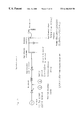
- FIG. 1 is a conceptual block diagram of a disassembling apparatus of an electronic appliance in an embodiment of the invention.
- FIG. 2 is a plan view of FIG. 1 .
- FIG. 3 is a flowchart of FIG. 1 .
- FIG. 4 is a conceptual diagram of a disassembling apparatus of an electronic appliance in an embodiment of the invention.
- FIG. 5 is an essential plan view of a disassembling apparatus of an electronic appliance in an embodiment of the invention.
- FIG. 6 is an essential side view of FIG. 5 .
- FIG. 7 is an essential plan view of FIG. 6 .
- FIG. 8 is an essential side view of a cleaning device in an embodiment of the invention.
- FIG. 9 is a flowchart of disassembling process of television receiver in an embodiment of the invention.
- FIG. 10 is an essential plan view of a housing disassembling apparatus in an embodiment of the invention.
- FIG. 11 is an essential side view of FIG. 10 .
- FIG. 12 is a perspective view of cutting groove processing in a housing in an embodiment of the invention.
- FIG. 13 is a perspective view in an opened state of the bottom after cutting groove processing in an embodiment of the invention.
- FIG. 14 is a perspective view in a opened disassembly state of four principal side of a housing in an embodiment of the invention.
- FIG. 15 is a conceptual block diagram of disassembling process of metal band for prevention implosion of a cathode-ray tube in an embodiment of the invention.
- FIG. 16 is an essential perspective view of disassembling apparatus of metal band for prevention of implosion in an embodiment of the invention.
- FIG. 17 is a circuit diagram of an equivalent circuit of high frequency heating means for composing FIG. 16 .
- FIG. 18 is an essential side view for an example of cathode-ray tube used in explanation of the invention.
- FIG. 19 is a flowchart of disassembling process in an embodiment of the invention.
- FIG. 20 (A) is a plan view of other conveying pallet used in the invention.
- FIG. 20 (B) is a sectional view cutting away FIG. 20 (A) along S 1 —S 1 .
- FIG. 21 (A) is a plan view of another conveying pallet used in the invention.
- FIG. 21 (B) is a sectional view cutting away FIG. 21 (A) along S 2 —S 2 .
- FIG. 22 is an essential side view of disassembling apparatus of metal band for prevention of implosion in an embodiment of the invention.
- FIG. 23 is an essential front view of tab pressing means for composing FIG. 22 .
- FIG. 24 is an essential sectional view of concept of process for measuring the outline of a cathode-ray tube in an embodiment of the invention.
- FIG. 25 is an essential sectional view of concept of measuring process from a distance sensor to a fluorescent screen of a cathode-ray tube in an embodiment of the invention.
- FIG. 26 is a flowchart of measurement to separation process of a cathode-ray tube in an embodiment of the invention.
- FIG. 27 is a conceptual block diagram of deposit removing device of a cathode-ray tube in an embodiment of the invention.
- FIG. 28 is an essential side view of deposit removing device of a cathode-ray tube in an embodiment of the invention.
- FIG. 29 is an essential plan view of FIG. 28 .
- FIG. 30 is an essential side view showing peeling region of each rotary brush for composing FIG. 28 .
- FIG. 31 is a flowchart of adhesive removal process in an embodiment of the invention.
- FIG. 32 is an essential plan view of a dresser device in an embodiment of the invention.
- High frequency heating device high frequency induction heating device
- Chassis (control circuit unit)
- Adhesive tape (including adhesive agent)
- the electronic appliance is represented by an example of a television receiver.
- FIG. 1 is a conceptual block diagram of a disassembling apparatus of an electronic appliance in an embodiment of the invention.
- FIG. 2 is a plan view of FIG. 1 .
- FIG. 3 is a flowchart of FIG. 1 .
- the television receiver is mounted on a conveying pallet, and is conveyed from the lower right corner to the upper left corner in FIG. 1 by the conveyor, for example, chain conveyors stretched parallel.
- the conveyor for example, chain conveyors stretched parallel.
- the steps from removal of back cover to peeling and removal of adhesive tape are half automated.
- Reference numerals 1 to 12 shown in FIG. 2 refer to the step numbers.
- Step 1 Loading device
- a discarded television receiver is discharged by mounting on a conveying pallet by means of a loading device.
- a conveying pallet In this embodiment, it is mounted on the conveying pallet manually.
- a lifting robot of discarded television receiver may be composed freely so as to, for example, suck the CRT surface by vacuum, or hold the both sides of the cabinet (housing) by two arms.
- Steps 2 to 4 Tilting device, cleaning device, tilting device
- a conveying pallet mounting a television receiver is delivered into the work bench of the side in which the conveying pallet has not been delivered yet.
- the worker removes the back cover of the housing positioned at the rear side of the housing (cabinet) for composing the television receiver.
- step 3 dust collected in the discarded television receiver is automatically removed by air blow.
- the television receiver is mounted together with the conveying pallet on the tiltable work bench, and the deflecting yoke (DY), chassis and others are removed manually.
- the members after removing the back cover, DY and others are mounted on the conveyor, and automatically discharged as specified.
- FIG. 4 is a side view of concept of tiltable work bench and cleaning device composed in the embodiment.
- FIG. 5 is an essential plan view of FIG. 4 .
- FIG. 6 is an essential side view of the tiltable work bench.
- FIG. 7 is a plan view of FIG. 6 .
- FIG. 8 is an essential side view of the cleaning device.
- a television receiver 100 is mounted on a conveying pallet 2 , and is conveyed from the left to right direction in FIG. 5 by means of a conveyor 1 .
- the television receiver 100 comprising a cabinet 101 and a back cover 102 delivered up to before a work bench 40 (left side in FIG. 5) is transferred from the conveyor 1 onto the first tiltable work bench 40 together with the pallet 2 , by an automatic transfer device, for example, a belt conveyor (not shown) driven in a direction orthogonal to chain conveyors stretched parallel.
- the worker is positioned before the tiltable work bench 40 .
- a start signal is sent by pressing, for example, a foot switch (not shown), so that the work bench 40 is tilted to a specified angle, for example, in a range of about 45 degrees to 75 degrees.
- the television receiver 100 mounted nearly in the center of the work bench slides on the conveying pallet, and hits against a stopper 32 , and is positioned in a range accessible by the worker. Then the worker removes the back cover 102 .
- the work bench is put back in horizontal state, and the conveying pallet 2 mounting the television receiver is returned onto the conveying 1 by the automatic transfer device.
- the returned television receiver is delivered into a cleaning device 45 of next step by the conveyor 2 .
- the work bench 40 is installed before and after the two cleaning devices 45 each.
- a first reason is to have a margin in the disassembling processing capacity of television receiver. That is, by this constitution, the working personnel can be increased depending on the processing amount.
- a second reason is to receive the conveyed television receiver on other work bench if next television receiver to be disassembled is conveyed while disassembling work is done on one of the two adjacent work benches. That is, the disassembling time varies with the size and type of the television receiver. Therefore, if a longer time than a specific processing time is taken, other working bench of two working benches functions as a spare one. In this case, as a matter of course, the worker moves to the adjacent work bench and handles.
- the structure of the tiltable work bench 40 is described specifically by referring to FIG. 6 and FIG. 7 .
- the work bench 40 is composed of a base frame 31 , parallel belt conveyors 39 , 39 assembled into the frame 31 , a drive cylinder 33 installed in the lower side of the frame 31 , and a base frame 34 .
- the belt conveyor 39 is composed of two parallel belts, and the belt conveyor 39 transfers the conveying pallet 2 nearly to the stopper 32 , and stops automatically.
- the frame 31 is mounted on the hinge so that the one end side may be rotatable, by means of a bearing 35 and a shaft 36 .
- a rod end member of the cylinder 33 is fitted on hinge through a shaft 37 .
- the other end of the cylinder 33 is fitted to the frame 34 through a shaft 38 .
- a link mechanism for rotating at each fulcrum is composed.
- the piston rod of the cylinder moves, and the frame 31 is tilted to a specified angle.
- the television receiver 100 or a large-sized television receiver 100 A is mounted on the pallet 2 .
- the plate may be tilted by fitting an eccentric disk on the motor shaft.
- the plate may be tilted by a cam mechanism or the like (neither shown).
- the television receiver 100 having cabinet 101 and CRT 103 being mounted on the conveying pallet 2 and conveyed to specified position by the conveyor 1 is isolated from the surrounding almost in airtight state by an enclosed box 46 descending from above. Near the ceiling of the enclosed box 46 , a spray nozzle 47 and an exhaust duct 48 are disclosed. In this way, the cleaning device 45 is constituted.
- a high pressure air shower 49 is injected toward the television receiver 100 from a plurality of spray nozzles 47 disposed near the ceiling.
- This high pressure air shower 49 blows off dust deposits from the components including the electron gun neck, DY and funnel of CRT, inside of cabinet, printed wiring board contained in cabinet, wiring, and others.
- the exhaust duct 48 is put in operation, and floating dust is sucked and discharged.
- the air injection time is set at about 5 seconds to scores of seconds.
- the enclosed box After cleaning of the television receiver, the enclosed box is raised, and the television receiver mounted on the conveying pallet 2 is sent to next step by the conveyor 1 .
- the television receiver is sent into a tiltable second work bench (the work bench located at the right side of the cleaning device in FIG. 5) together with the conveying pallet.
- the DY unit the deflecting yoke, neck printed board, etc.
- chassis furnished to the neck of the CRT are removed.
- the DY unit removing step since the inside of the television receiver is cleaned beforehand, floating dust is decreased substantially, and hence there is no adverse effect on the working environments and equipment.
- the CRT attached to the cabinet is sent forward to next step of cabinet cutting process and CRT dismounting process by the conveyor together with the conveying pallet.
- dismounting of back cover and DY unit, and dust removal in the cabinet can be done efficiently, and the subsequent disassembling procedure can be automated.
- the tiltable work bench can pretreat the television receivers in various inch sizes and shapes efficiently.
- FIG. 9 is a flowchart of disassembling process of television receiver in an embodiment of the invention.
- FIG. 10 is an essential plan view of a housing disassembling device in an embodiment of the invention.
- FIG. 11 is an essential side view of FIG. 10 .
- FIG. 12 is a perspective view of a process for forming a U-form cutting groove in the principal plane (bottom plane/bottom plate) of the housing for disassembling the housing of a video appliance.
- FIG. 13 is a perspective view of an opened state of the bottom plane (bottom plate) after finishing the process of the cutting groove.
- FIG. 14 shows a disassembled state of opening four principal planes of the housing.
- the television receiver 100 shown in FIG. 9 through FIG. 13 is composed of a cathode-ray tube 51 (or CRT), a housing (cabinet) 50 connected to the end of the outer circumference of the CRT 51 by screws, a chassis (including control circuit) 52 accommodated in the housing 50 , a speaker unit 55 installed near the CRT 51 , an antenna terminal board 54 , a tuner 56 , and printed wiring boards 53 , 57 mounted on side plate, among others.
- a metal band (reinforcing band for preventing implosion) 58 is wound on the outer circumference (the end of the display screen surface), and mounting tabs 59 are disposed at four positions by spot welding or other means.
- FIG. 9 is a flowchart of “cutting groove processing, disassembling, and constituent member dismounting” of the TV housing.
- FIG. 10 shows the state of mounting a discarded TV on the conveying pallet 2 , and transferring to the specified position, that is, step 2 A.
- step 3 A the conveying pallet 2 put on the plate 10 placed at the leading end of the air cylinder 9 is raised above the conveyor 1 (step 3 A). Then, the housing 50 of the discarded TV is positioned in the X-axis and Y-axis direction (position establishing: step 4 A).
- Positioning of the housing 50 in the Y-axis direction is effected by the Y-axis direction positioning means 6 having two confronting air cylinders 4 , 4 , and plates 5 , 5 mounted at the ends of the cylinders 4 .
- the timing is controlled, of course, so that either one of the two air cylinders may advance first to the specified position, so that the other air cylinder may advance later.
- Positioning in the X-axis direction is similarly effected by X-axis direction positioning means 3 . This positioning is executed at a specified timing by means of an air cylinder 7 moving up and down in the Z-axis direction, an air cylinder in the X-axis direction not shown, and a plate 8 fitted to the end of the cylinder 7 .
- step 5 A position measurement of principal planes
- Measurement of position of principal planes is a step to be ready for cutting groove process at next step 6 A, and a non-contact sensor, such as laser beam sensor, or ultrasonic sensor is used.
- a non-contact sensor such as laser beam sensor, or ultrasonic sensor is used.
- principal planes (bottom, top, both sides) of the housing 50 are measured and identified.
- a cutting tool 13 such as end mill is driven as specified.
- the principal planes of the housing 50 are cut by cutting means (at least one means of, for example, end mill processing of high speed rotation, laser processing, and water jet processing).
- Rotating and driving means 12 for rotating the cutting tool 13 as specified may be executed arbitrarily by using general 3-axis to 5-axis control robot 11 (for example, scalar robot).
- the rotating speed of the end mill tool 13 is about hundreds to 25,000 rpm when the tool diameter is 3 mm to 20 mm.
- the rotating speed is about 8,000 rpm to 10,000 rpm.
- a U-form cutting groove 60 is processed in the bottom (bottom plate) of the housing 50 by two each of rotating and driving means 12 and cutting tools (end mills) 13 . It is also possible to cut by using only one each of rotating and driving means 12 and cutting tool 13 .
- step 7 A a step for lowering the conveying pallet
- step 8 A a step for transferring the conveying pallet to next process
- step 9 A the nuts clamping the mounting tab 59 are detached by robot (not shown) or manually.
- the CRT 51 , tuner 56 , antenna terminal board 54 , chassis 52 , printed wiring board 53 , and speaker unit 55 are dismounted manually or by robot (neither shown). Then it is transferred to the classification and regeneration process of step 9 A.
- folding and opening operation of the principal planes of the housing 50 and dismounting operation of constituent members should be preferably done in other process than cutting groove processing, but may be done in the same process as the cutting process.
- exchange, addition or deletion of steps may be done as desired.
- the shape and forming position of the cutting groove are not particularly limited, and it may be formed in any desired shape and position.
- the groove may be formed while leaving occasional linking portions so that the principal planes may not collapse in the midst of processing, in ridges of four corners in the Z-axis direction (intersection of top and side, and intersection of bottom and side), X-axis direction, and Y-axis direction.
- a U-form cutting groove may be formed also on the top and both sides.
- the housing rotating means not shown, the housing may be rotated by 90 degrees repeatedly (rotation, measurement of position of principal planes, and cutting process).
- FIG. 14 shows the disassembled state by opening four principal planes of the housing.
- the principal planes may be pushed down and opened by force in other process.
- the groove cutting tool when high speed rotating means such as end mill is used as the groove cutting tool, it can be operated in dry process without using water.
- Laser processing realizes three-dimensional processing more easily, and curvature processing can be done at high speed.
- Water jet processing can be applied not only in cutting of housing, but also in glass cutting of CRT.
- step 5 in FIG. 3 disassembling work of discarded TV (housing bottom plate cutting) can be automated.
- Steps 6 to 7 CRT dismounting device to CRT transfer device
- step 6 the worker removes tightening screws, and dismounts the CRT from the cabinet. Peripheral parts (grounding wire, demagnetization coil, etc.) are also detached.
- step 7 the cabinet, removed parts, and CRT are conveyed to next CRT processing step on the conveying pallet.
- Step 8 Electron gun cutting
- a diamond wheel of about 200 mm in outside diameter, and thickness of 2 mm or less is rotated at about 3,000 rpm to 5,000 rpm, and is forwarded straightly in one direction or in a moderate arc, so that the electron gun neck of the CRT is cut off.
- the separated electron gun is conveyed to the recycling process, while the CRT is sent to the next step.
- the metal band for prevention of implosion around the CRT is removed by high frequency heating.
- FIG. 15 is a conceptual block diagram of disassembling process of metal band for prevention implosion of a cathode-ray tube in an embodiment of the invention, showing an essential block diagram of the disassembling apparatus as seen from the side direction.
- FIG. 16 is an essential perspective view of disassembling apparatus of metal band for prevention of implosion in an embodiment of the invention.
- FIG. 17 is a circuit diagram of an equivalent circuit of high frequency heating means for composing FIG. 16 .
- FIG. 18 is an essential side view of an example of cathode-ray tube used in explanation of the invention.
- FIG. 19 is a flowchart of disassembling process in an embodiment of the invention.
- a cathode-ray tube 51 shown in FIG. 18 comprises a panel, a funnel, a neck, an implosion preventive metal band 58 wound around the panel, and mounting tabs 59 fitted at four corners of the implosion preventive metal band by spot welding.
- the internal structure of the cathode-ray tube is not explained herein because it is not the main subject.
- the conveying pallet 2 is put on the conveying means of the conveyor 1 , and is transferred by a specific constant pitch.
- a high frequency heating device (specifically, high frequency induction heating device) 24 is installed at a specified position at the upper side of the conveyor 1 .
- Tab pressing means 21 acts to press the mounting tabs 59 always by a force of 4 kg to 6 kg when heating the implosion preventive metal band 58 .
- An induction heating coil 25 is installed in the high frequency heating device 24 in order to heat the implosion preventive metal band 58 at 350 to 500° C.
- CRT lifting means 23 is installed for lifting the CRT up to specified position in the induction heating coil 25 through the opening (penetration hole) provided in the center of the conveying pallet 2 .
- CRT supporting means 22 having four pin members is planted and installed at the CRT mounting surface side of the conveying pallet 2 .
- Disassembling procedure of implosion preventive metal band of a general cathode-ray tube is explained below.
- a flowchart of an embodiment of disassembling procedure is given in FIG. 19 .
- the cathode-ray tube 51 mounted by supporting the panel surface on the conveying pallet 2 is fed by specified pitch and positioned at the lower part of the high frequency heating device (specifically, high frequency induction heating device) 24 .
- the cathode-ray tube 51 is then lifted to a specified position in the induction heating coil 25 by the CRT lifting means 23 .
- the tab pressing means 21 descends, and the tab pressing means 21 presses the mounting tabs at four positions with a force of 4 kg to 6 kg each.
- the high frequency heating device 24 is operated, and the implosion preventive metal band 58 is heated to 350 to 500° C.
- 180 V, 200 A was applied for 5 to 50 seconds at 1500 to 2000 Hz.
- the application time of the high frequency heating device is about 15 seconds in the case of a 20-inch CRT.
- the implosion preventive heating band 58 is suddenly heated and expanded. As a result, the metal band 58 falls in a reverse state of shrinkage fitting.
- the resin impregnated in the incombustible buffer material or undercoat resin for example, acrylic resin, polyester resin, or urethane resin
- the adhesion of the resin becomes lower than the pressing force, so that the implosion preventive metal band 58 is separated from the panel.
- a falling implosion preventive metal band 58 is indicated by single dot chain line.
- the cathode-ray tube 51 is transferred by a specific pitch.
- the implosion preventive metal band 58 is removed from the conveying pallet 2 . Thereafter, specified regeneration process is done individually for regeneration of cathode-ray tube glass and regeneration of implosion preventive metal band.
- FIG. 19 Two examples of removing the implosion preventive metal band 58 from the conveying pallet 2 are shown in FIG. 19 .
- the procedure shown in FIG. 19 is not particularly limited, and steps may be added, deleted, or changed as required.
- the high frequency output of the high frequency heating device used in the embodiment is a maximum of 60 kW at a frequency in a range of 0.5 kHz to 2000 kHz.
- the output and frequency may be set freely depending in the inch size of the cathode-ray tube.
- the lower limit output may be about 2 kW.
- the conveying means of the conveying pallet is not particularly limited, and, for example, roll conveyor, belt conveyor, roller conveyor, chain conveyor, or pusher method using fluid cylinder may be employed.
- the tab pressing means 21 is not particularly limited, and, for example, air cylinder, compression coil spring or others may be used.
- the pressing load may be 4 kg or more each, allowable up to 100 kg as far as the cathode-ray tube is not broken, and preferably it is in a range of 4 to 40 kg.
- the front end shape of the tab pressing means 21 is not particularly limited, and an arbitrary shape may be employed.
- four independent pressing pins corresponding to the tabs 59 are provided.
- the tab pressing means 21 A composed of a pair of T-form plates grips the side surface of the metal band 58 of the CRT 51 , and positions the CRT 51 at specified position in the horizontal direction. Releasing this gripping force, consequently (the gripping position of the T-form plates remaining unchanged or slightly moved back), the T-form plates 21 A descend in the vertical direction to press down the tabs 59 . One plate (one side) of the T-form plates 21 A presses two tabs 59 each.
- FIG. 20 (A) is a plan view of other conveying pallet used in the disassembling device of the implosion preventive metal band of the cathode-ray tube in the invention, and FIG. 20 (B) is a sectional view cutting away FIG. 20 (A) along S 1 —S 1 .
- FIG. 21 (A) is a plan view of another conveying pallet used in the invention, and FIG. 21 (B) is a sectional view cutting away FIG. 21 (A) along S 2 —S 2 .
- the conveying pallet 2 A in FIG. 20 (A) and the conveying pallet 2 B in FIG. 21 (A) are plate members made of wood, aluminum or other metal, or ABS, duracon or other resin.
- the outline of the conveying pallet is nearly rectangular.
- specified recesses are formed at four positions on the circumference, and penetration holes 27 A, 27 B are formed in the center.
- annular recess 29 of one size larger is formed in stairs.
- a ring-form elastic member 26 is fitted in the annular recess 29 .
- the ring-form elastic member 26 is made of either rubber member or plastic member having a hardness of 35 to 50 degrees, or in a combination thereof.
- the rubber material is not particularly limited, and, for example, silicone rubber, fluororubber, butyl rubber, urethane rubber, natural rubber, or other arbitrary member may be used. Of course, a rubber member foamed like sponge may be also used.
- the plastic material is not particularly limited, and, for example, silicone system, vinyl chloride system, nylon system, styrol system, and other arbitrary plastic member may be used.
- the cathode-ray tube (CRT) to be disassembled is mounted on the center of the conveying pallets 2 A, 2 B with the tube side down (in FIGS. 20 (B), 21 (B), the cathode-ray tube is shown by twin dot chain line).
- the ring-form elastic member 26 is elastically deformed by the own weight of the cathode-ray tube 51 , and contacts tightly along the tube surface of the cathode-ray tube 51 .
- the cathode-ray tube 51 maintains the initial mounted position without deviation of position.
- elastic members pieces 28 are disposed nearly at equal divided angles at three positions on the upper peripheral edge of the penetration hole 27 B.
- the constituent member of the elastic member pieces 28 same materials as in FIG. 20 may be used.
- FIG. 21 since the cathode-ray tube is supported at three points, positioning of the cathode-ray tube is further stabilized as compared with the case in FIG. 20 .
- the cathode-ray tube 51 maintains the initial mounted position without deviation of position.
- the outline of the conveying pallets 2 A, 2 B is not particularly limited, and any shape may be used.
- the shape of the penetration holes 27 A, 27 B is not limited to circle, but rectangular or other shape may be used.
- the implosion preventive band can be removed efficiently in a short time. Large equipment is not needed. Deviation of position of cathode-ray tube mounted on the conveying pallet can be prevented.
- step 10 presence or absence of safety glass adhered to the panel surface of the CRT is judged, and the CRT having safety class is classified, and conveyed to next process.
- CRT double panel measuring device CRT judging device
- FIG. 24 is an essential sectional view of concept of process for measuring the outline of a cathode-ray tube in an embodiment of the invention.
- FIG. 25 is an essential sectional view of concept of measuring process from a distance sensor to a fluorescent screen of a cathode-ray tube in an embodiment of the invention.
- FIG. 26 is a flowchart of measurement to separation process of a cathode-ray tube in an embodiment of the invention.
- the cathode-ray tube 51 is mounted on a specified position of the conveying pallet 2 having a penetration hole 91 and data carrier 92 in the center, with the picture display side (tube side) down.
- the conveying pallet 2 may be either same as the conveying pallet described in FIG. 20 and FIG. 21, or a different type of different line.
- the vertical dimension or lateral dimension c of the panel of the cathode-ray tube 51 is measured by a distance sensor 93 .
- the picture display screen size (tube screen size) of the cathode-ray tube is judged.
- the measured value and judged data are stored in general memory means (not shown).
- the length dimension c of the cathode-ray tube 51 is measured from the length a between the confronting distance sensors 93 , and the lengths b1, b2 from the distance sensors 93 to the panel of the cathode-ray tube 51 .
- a measuring unit 95 comprising the distance sensors 94 is fitted to contact with the picture display screen. Then the distances h1, h2 from the distance sensors 94 to the fluorescent screen of the cathode-ray tube 51 are measured.
- the left side shows a general cathode-ray tube 51 , not having safety glass at the picture display side.
- the right side shows a cathode-ray tube 51 A of special specification having a safety glass 80 disposed through an adhesive agent 81 (for example, unsaturated polyester resin).
- the thickness of the safety glass 80 is about 2 mm to 3 mm, the plate thickness of the panel picture display unit is about 10 mm, the thickness of the adhesive agent 81 is about 2 mm, and the interval of the picture display screen and distance sensors 94 is about 20 mm.
- the measuring distance differs about 5 mm depending on the presence or absence of the safety glass 80 . It means that the measuring precision of the distance sensors 94 may be rough, and an inexpensive measuring apparatus can be used. As the distance sensors 94 , laser beam, ultrasonic wave, or other arbitrary sensors may be used.
- the distance (measurement) between the distance sensor fluorescent screens and the type of tube are judged. That is, the measuring unit 95 contacts with the picture display screens of the cathode-ray tubes 51 , 51 A. Next, by the laser type distance sensors 94 , the distances h1, h2 from the fluorescent screens applied on the inside of the panel of the cathode-ray tubes 51 , 51 A are measured.
- Measured values of h1, h2 are compared with the distance “H value” from the distance sensors to the fluorescent screens put in the computer preliminarily.
- the H value is defined in each inch size. Therefore, the H value is set automatically according to the outline dimension information at step 1 C.
- H is nearly equal to h1
- the cathode-ray tube placed on the conveying pallet 2 is judged to be an ordinary cathode-ray tube (without safety glass) 51 .
- H is smaller than h2
- the difference of H and h2 is about 3 mm to 4 mm or more
- the cathode-ray tube is judged to be a cathode-ray tube 51 A with safety glass.
- the measured data and judged result are transmitted and stored in a mechanical data carrier 92 furnished to the conveying pallet 2 .
- the data carrier 92 is moved to the left.
- optical, microwave, or other arbitrary means may be employed.
- cathode-ray tubes put on the conveying pallet 2 are classified into general cathode-ray tubes 51 and cathode-ray tubes with safety glass 51 A. That is, the data in the data carrier 92 is read, and when the data is judged to be cathode-ray tube with safety glass 51 A, this cathode-ray tube 51 A is automatically transferred to other line. As a result, adhesive agent 81 such as unsaturated polyester resin is prevented from being mixed into the cullet.
- the cathode-ray tubes 51 , 51 A are separated into the panel and funnel.
- each line of cathode-ray tubes 51 without safety glass and cathode-ray tubes 51 A with safety glass the boundary of the panel and funnel of the cathode-ray tube is cut in a groove of specified depth circularly by a disk-shaped diamond cutter.
- the groove is then heated, and the panel and funnel are separated by making use of difference in thermal stress and thermal expansion.
- the disk-shaped diamond cutter is 80 mm to 120 mm in diameter, 0.2 mm to 2 mm in disk thickness, and 2,000 rpm to 10,000 rpm in rotating speed, and water is used as coolant.
- the groove cutting depth is about 0.2 to about 2 mm.
- the picture display size of the cathode-ray tube can be identified and presence or absence of safety glass can be judged automatically, and the cathode-ray tube can be automatically separated into the panel and funnel at high productivity.
- the adhesive tape 72 glued to the side of the cathode-ray tube 51 is peeled off, or the adhesive agent of the adhesive tape 72 is scraped off.
- deposit removing method of cathode-ray tube and its apparatus are described by referring to FIGS. 27 through 32.
- FIG. 27 is a conceptual block diagram of deposit removing device of a cathode-ray tube in an embodiment of the invention.
- FIG. 28 is an essential side view of deposit removing device of a cathode-ray tube in an embodiment of the invention.
- FIG. 29 is an essential plan view of FIG. 28 .
- FIG. 30 is an essential side view showing peeling region of each rotary brush for composing FIG. 28 .
- FIG. 31 is a flowchart of removal process of residual adhesive agent of adhesive tape or adhesive agent.
- FIG. 32 is an essential plan view of a dresser device in an embodiment of the invention.
- a deposit removing device 70 of cathode-ray tube is composed of a rotary brush 73 having steel wires planted radially, a brush rotating motor 74 , a CRT suction pad 75 for sucking the tube surface of CRT 51 by vacuum, a CRT rotating motor 76 , an elevating unit 77 for elevating and lowering the sucked CRT 51 , a brush support arm 78 for supporting the rotary brush 73 and motor 74 , a brush moving cylinder 79 for contacting and separating the rotary brush 73 and CRT 51 , a tape recovery box 82 of adhesive tape 72 peeled off from the side wall of the CRT 51 by the rotary brush 73 , a cylinder 83 for moving the tape recovery box 82 , a CRT pressing cylinder 84 for holding the CRT 51 between an exhaust duct 85 for collecting the adhesive tape or brush dust generated in the peeling process of adhesive tape and suction pad 75 , a conveying pallet 2 for mounting and conveying CRT, and
- the adhesive tape 72 serving as shock absorber by fixing the metal band to the cathode-ray tube 51 generally, a glass cloth tape impregnated with organic resin such as acrylic adhesive is used.
- the rotary brush 73 for peeling and removing the adhesive tape 72 is formed by planting steel wires, stainless steel wires, brass wires, or other metal wires of diameter of 0.2 mm to 0.8 mm, radially and densely on the surface of a hub.
- the outside diameter of the brush is about 200 mm, and the brush width is about 40 mm.
- rotating speed of the brush is variable in a range of about 3,000 to about 12,000 rpm.
- the rotating direction of the rotary brush 73 is reversible in normal and reverse directions.
- the rotary brush 73 comprises rotary brushes 73 A, 73 B, 73 C, 73 D, and these rotary brushes 73 are disposed at four positions corresponding to the side walls of the CRT 51 , so as to press against the side wall at a specified pressing force.
- the arrow in FIG. 29 indicates the rotating direction.
- the rotary brushes 73 A, 73 B, 73 C, 73 D are disposed by sequentially deviated in the vertical direction of the CRT 51 , from the first peeling region to the fourth peeling region.
- the adhesive tape can be securely peeled off along the width of about 100 mm.
- the conveying pallet 2 for mounting and conveying the CRT 51 has a penetration hole for elevating and lowering the CRT suction pad 75 in the center.
- step 1 D the conveying pallet 2 mounting the CRT 51 is delivered into the cleaning chamber of the deposit removing device 70 .
- step 2 D the conveying pallet 2 is positioned at a specified position. Consequently, at step 3 D, the elevating unit 77 operates, the CRT suction pad 75 supports the panel surface of the CRT and goes up, and the suction pad 75 sucks the panel surface in vacuum and fixes. At step 4 D, the CRT pressing cylinder 84 descends, and the cylinder 84 presses near the neck of the electron gun of the CRT 51 , and the CRT 51 is held between the pressing cylinder 84 and CRT suction pad 75 .
- the tape recovery box 82 for collecting the peeled adhesive tape moves forward toward the CRT 51 .
- the brush 73 abuts against the wall of the CRT 51 while rotating at about 10,000 rpm.
- the CRT 51 rotates one turn in the clockwise direction.
- the CRT 51 descends by about 50 mm in the vertical direction.
- step 9 D the CRT 51 rotates one turn in the counterclockwise direction. In this period, the rotating direction of the brush 73 may be changed over properly.
- step 10 D the recovery box 82 and brush 73 are separated from the CRT 51 , and return to the initial position.
- suction of the CRT bulb surface is released.
- step 12 D the CRT suction pad 75 descends.
- the CRT pressing cylinder 84 moves up.
- step 13 D the CRT 51 is mounted on the conveying pallet 2 , and is discharged outside of the deposit removing device.
- the dresser device as shown in FIG. 32 can be used as the means for showing always a fresh abutting surface of the brush.
- a dresser 62 made of cylindrical porous ceramic or grinding wheel piece is fitted to the tip of the brush 61 , so that the tip of the brush 61 coated with the deposit 67 is ground.
- coolant such as water from coolant feed means 64 , the grinding effect is enhanced while cooling action is achieved.
- an adhesive tape (adhesive tape and adhesive agent) 72 is adhered to the surface of the side wall 63 of the CRT. As the brush 61 rotates, the deposit 67 formed on the tip of the brush 61 is removed by the dresser 62 .
- the planting width and outside diameter of the brushes 61 , 73 , wire material, rotating speed and others can be set freely.
- the presence or absence of the dresser device is also arbitrary. Still more, instead of the lowering action of the CRT at step 9 D, the rotary brush side can be moved up and down.
- deposits such as adhesive tape left over on the CRT bulb side can be removed in dry process, efficiently, and in a short time.
- Step 12 CRT transfer device
- the CRT is conveyed to the CRT classification process to be classified into the panel and funnel by CRT transfer device ( 12 ) in FIG. 2 .
- the dissembling object is not limited to the video appliances (television receiver, personal computer, or display monitor), but it can be applied to any electronic appliances such as audio appliances and air-conditioners.
- disassembling of the television receiver, electric household appliances, and electronic appliances can be realized in dry process.
- the process from detaching of back lid of housing, to peeling and removing of adhesive tape glued to the side of the CRT can be automated or half automated in a simple facility.
- classification and regeneration process is facilitated.
- the recycling efficiency is enhanced, the environments can be preserved, and the sources can be utilized effectively.
Landscapes
- Engineering & Computer Science (AREA)
- Environmental & Geological Engineering (AREA)
- Manufacturing & Machinery (AREA)
- Mechanical Engineering (AREA)
- Processing Of Solid Wastes (AREA)
- Manufacture Of Electron Tubes, Discharge Lamp Vessels, Lead-In Wires, And The Like (AREA)
Applications Claiming Priority (16)
| Application Number | Priority Date | Filing Date | Title |
|---|---|---|---|
| JP8-199933 | 1996-07-30 | ||
| JP19993396A JP3275720B2 (ja) | 1996-07-30 | 1996-07-30 | 廃棄映像機器の解体方法とその装置 |
| JP8-199932 | 1996-07-30 | ||
| JP19993296A JP3024559B2 (ja) | 1996-07-30 | 1996-07-30 | 陰極線管の爆縮防止用金属バンドの解体方法 |
| JP8-236337 | 1996-09-06 | ||
| JP23633796A JP2985792B2 (ja) | 1996-09-06 | 1996-09-06 | 陰極線管の判別方法と判別装置と処理方法 |
| JP8254131A JP2904148B2 (ja) | 1996-09-26 | 1996-09-26 | プリント配線基板の処理装置 |
| JP8-254131 | 1996-09-26 | ||
| JP9-047523 | 1997-03-03 | ||
| JP4752397A JP3147806B2 (ja) | 1997-03-03 | 1997-03-03 | 陰極線管の爆縮防止用金属バンド解体装置 |
| JP9-051335 | 1997-03-06 | ||
| JP5133597A JP3045094B2 (ja) | 1997-03-06 | 1997-03-06 | 傾斜可能な作業台と電子機器の処理方法と処理装置 |
| JP9-058920 | 1997-03-13 | ||
| JP5892097A JP3214386B2 (ja) | 1997-03-13 | 1997-03-13 | 陰極線管の付着物除去方法と除去装置 |
| JP6765097A JP3097589B2 (ja) | 1997-03-21 | 1997-03-21 | 電子機器の解体装置と処理方法 |
| JP9-067650 | 1997-03-21 |
Publications (1)
| Publication Number | Publication Date |
|---|---|
| US6186848B1 true US6186848B1 (en) | 2001-02-13 |
Family
ID=27572356
Family Applications (1)
| Application Number | Title | Priority Date | Filing Date |
|---|---|---|---|
| US08/896,015 Expired - Fee Related US6186848B1 (en) | 1996-07-30 | 1997-07-17 | Disassembling method of electronic appliance and disassembling apparatus thereof |
Country Status (7)
| Country | Link |
|---|---|
| US (1) | US6186848B1 (fr) |
| EP (2) | EP1393825B1 (fr) |
| CN (2) | CN1189254C (fr) |
| BR (1) | BR9704099A (fr) |
| CZ (1) | CZ290226B6 (fr) |
| DE (2) | DE69736725T2 (fr) |
| MY (2) | MY123846A (fr) |
Cited By (12)
| Publication number | Priority date | Publication date | Assignee | Title |
|---|---|---|---|---|
| US20020132549A1 (en) * | 2001-03-13 | 2002-09-19 | Harry Braunstein | Monitor opening saw |
| US20030233919A1 (en) * | 2002-06-20 | 2003-12-25 | Greg Yourkievitz | Pneumatic cathode ray tube cutting system |
| US20050020178A1 (en) * | 2002-03-22 | 2005-01-27 | Rauno Holappa | Method for dismantling electronic products containing cathode-ray tubes and for recycling the materials |
| US20080056326A1 (en) * | 2006-08-21 | 2008-03-06 | Laserresearch (S) Pte Ltd | Process And Apparatus For Laser Selective Separation |
| US20110263175A1 (en) * | 2009-01-15 | 2011-10-27 | Sharp Kabushiki Kaisha | Dismantling Apparatus for Flat-Screen TV and Dismantling Method for Flat-Screen TV |
| US20130104712A1 (en) * | 2005-06-03 | 2013-05-02 | Crt Heaven Ltd | Apparatus and Method for Cutting a Cathode Ray Tube |
| US20130234026A1 (en) * | 2010-09-24 | 2013-09-12 | Nec Tokin Corporation | Pyroelectric infrared detecting device, and method for replacing pyroelectric element in pyroelectric infrared detecting device |
| CN103990642A (zh) * | 2014-05-19 | 2014-08-20 | 南京凯燕电子有限公司 | 废旧电视机拆解设备及拆解方法 |
| CN106346428A (zh) * | 2016-09-27 | 2017-01-25 | 无锡市明骥智能机械有限公司 | 具备照明辅助和振荡清洗功能的切割工作台 |
| CN108857311A (zh) * | 2018-07-19 | 2018-11-23 | 林焕城 | 一种喷漆治具板热熔拆解设备 |
| CN113102444A (zh) * | 2021-03-22 | 2021-07-13 | 石家庄绿色再生资源有限公司 | 废旧空调分解系统 |
| CN116116820A (zh) * | 2022-12-03 | 2023-05-16 | 侯佳俊 | 一种高效低成本芯片去胶装置及去胶工艺 |
Families Citing this family (26)
| Publication number | Priority date | Publication date | Assignee | Title |
|---|---|---|---|---|
| AU2002309275A1 (en) * | 2002-05-22 | 2003-12-02 | Refri S.R.L. | Cutting machine for picture tubes to recover and/or dispose of polluting materials |
| DE102004060142B3 (de) * | 2004-12-14 | 2006-05-04 | Engmann, Thomas | Verfahren und Vorrichtung zur Demontage von Bildschirmgeräten |
| CN100586648C (zh) * | 2006-06-19 | 2010-02-03 | 欣竑科技有限公司 | 一种在自动取、卸刀具的设备上传递置具盒的方法 |
| WO2008003323A1 (fr) * | 2006-07-06 | 2008-01-10 | H.J. Hansen Elektromiljø A/S | Procédé et machine de d;montage d'appareils équipés d'un afficheur |
| FR2943263B1 (fr) * | 2009-03-23 | 2011-06-10 | Cladil Sarl | Dispositif de decoupe et procede de decoupe correspondant |
| CN101817013A (zh) * | 2010-05-10 | 2010-09-01 | 大连东泰产业废弃物处理有限公司 | 阴极射线管无害化处理方法 |
| CN102500594B (zh) * | 2011-10-11 | 2013-09-11 | 黄石捷德万达金卡有限公司 | 一种无损回收非接触芯片模块的方法 |
| CN103170490B (zh) * | 2011-12-20 | 2015-08-26 | 华星集团环保产业发展有限公司 | 一种废旧电视机拆解流水工艺及设备 |
| JP5585669B2 (ja) * | 2013-01-16 | 2014-09-10 | 三菱マテリアル株式会社 | 固定部材解体システム、固定部材解体方法、およびプログラム |
| CN104176923B (zh) * | 2013-05-22 | 2016-12-28 | 兰州大学 | 一种crt玻壳锥屏分离自动化设备 |
| CN104029302A (zh) * | 2014-06-26 | 2014-09-10 | 潘磊 | 耐火砖立铣除尘装置 |
| CN106670204A (zh) * | 2015-11-05 | 2017-05-17 | 宁夏琪凯节能设备有限公司 | 一种节能型电视机拆解处理装置 |
| CN106514198B (zh) * | 2016-11-29 | 2018-09-11 | 郑州德凯科技有限公司 | 一种全自动自适应式除胶划痕一体机 |
| CN106514199B (zh) * | 2016-11-29 | 2018-10-09 | 郑州德凯科技有限公司 | 一种全自动自适应式crt电器分离系统 |
| CN106493509B (zh) * | 2016-11-29 | 2018-09-11 | 郑州德凯科技有限公司 | 一种全自动快速去钢带机 |
| CN107009135B (zh) * | 2017-05-27 | 2023-02-07 | 河南核净洁净技术有限公司 | 一种对低放射性折叠式废过滤器进行拆解的设备及其方法 |
| CN107127653A (zh) * | 2017-06-29 | 2017-09-05 | 安徽力丰实业有限公司 | 一种石材板上料机 |
| CN107150063A (zh) * | 2017-07-11 | 2017-09-12 | 山东大学深圳研究院 | 一种键盘内部组件的自动拆卸和回收装置 |
| CN107878985B (zh) * | 2017-10-26 | 2019-08-27 | 杭州电子科技大学 | 一种物流包裹智能分拣系统及其分拣方法 |
| CN109530915A (zh) * | 2018-11-28 | 2019-03-29 | 杭州德意电器股份有限公司 | 一种油烟机内胆的激光焊接装置 |
| CN110606344A (zh) * | 2019-08-23 | 2019-12-24 | 杭州优智物联科技有限公司 | 一种智能化的生产线调度系统 |
| CN111730356A (zh) * | 2020-07-22 | 2020-10-02 | 清远市东江环保技术有限公司 | 一种电视回收设备 |
| CN111950963A (zh) * | 2020-08-21 | 2020-11-17 | 桂林电子科技大学 | 一种基于互联网的电子元器件智能管理平台 |
| CN112312700B (zh) * | 2020-10-23 | 2022-03-01 | 江西远大保险设备实业集团有限公司 | 一种便于移动的信息化综合控制管理柜 |
| CN116401112B (zh) * | 2023-05-31 | 2023-12-12 | 湖南开放大学(湖南网络工程职业学院、湖南省干部教育培训网络学院) | 一种计算机应用节点的安全检测装置及其检测方法 |
| CN117415593A (zh) * | 2023-08-11 | 2024-01-19 | 国营芜湖机械厂 | 一种航空液压柱塞泵分解清洗工作站及其工艺方法 |
Citations (13)
| Publication number | Priority date | Publication date | Assignee | Title |
|---|---|---|---|---|
| US4902258A (en) * | 1984-10-30 | 1990-02-20 | International Business Machines Corp. | Robotic assembly system |
| JPH05185064A (ja) | 1992-01-16 | 1993-07-27 | Hitachi Ltd | 廃棄テレビジョンの処理方法 |
| JPH05253550A (ja) | 1992-03-09 | 1993-10-05 | Sanpo Denki Kk | 物品清浄装置 |
| EP0593143A2 (fr) * | 1992-10-12 | 1994-04-20 | VICOR GmbH, Video Computer Recycling | Procédé pour le recyclage de tubes de téléviseurs |
| DE4316512C1 (de) | 1993-05-17 | 1994-09-08 | Harald Lueck | Verfahren zum Zerlegen von Anzeigegeräten in recyclebare Bestandteile |
| US5352142A (en) * | 1992-09-10 | 1994-10-04 | Hetzel & Co. Elektronik-Recycling Gmbh | Method of reprocessing picture tubes |
| US5439406A (en) * | 1992-10-09 | 1995-08-08 | Sony Corporation | Method for peeling the safety panel of a CRT |
| US5466984A (en) * | 1991-12-26 | 1995-11-14 | Sony Corporation | Implosion-resistant band with stack retainer |
| JPH0864140A (ja) * | 1994-08-22 | 1996-03-08 | Sony Corp | 補強型陰極線管の安全ガラスの再生方法 |
| DE4435365A1 (de) * | 1994-09-22 | 1996-03-28 | Eggers Umwelttechnik Gmbh | Verfahren und Vorrichtung zum Reinigen von Bildröhren |
| JPH08185800A (ja) | 1994-12-27 | 1996-07-16 | Sony Corp | Crt機器分離解体装置 |
| JPH08185801A (ja) | 1994-12-27 | 1996-07-16 | Sony Corp | Crt機器分離解体方法及び装置 |
| EP0729170A1 (fr) | 1995-02-23 | 1996-08-28 | Sony Corporation | Dispositif et procédé pour collecter des tubes à rayons cathodiques usagés |
Family Cites Families (1)
| Publication number | Priority date | Publication date | Assignee | Title |
|---|---|---|---|---|
| CH685191A5 (de) * | 1991-11-13 | 1995-04-28 | Inter Recycling Ag | Verfahren und Anlage zum Entsorgen von Bildröhren (Kathodenstrahlröhren). |
-
1997
- 1997-06-28 CN CNB97114009XA patent/CN1189254C/zh not_active Expired - Fee Related
- 1997-06-28 CN CNB2004100422917A patent/CN1259157C/zh not_active Expired - Fee Related
- 1997-07-17 US US08/896,015 patent/US6186848B1/en not_active Expired - Fee Related
- 1997-07-22 DE DE1997636725 patent/DE69736725T2/de not_active Expired - Lifetime
- 1997-07-22 DE DE1997627734 patent/DE69727734T2/de not_active Expired - Lifetime
- 1997-07-22 EP EP20030027877 patent/EP1393825B1/fr not_active Expired - Lifetime
- 1997-07-22 EP EP19970112508 patent/EP0822014B1/fr not_active Expired - Lifetime
- 1997-07-24 CZ CZ19972371A patent/CZ290226B6/cs not_active IP Right Cessation
- 1997-07-25 BR BR9704099A patent/BR9704099A/pt not_active Application Discontinuation
- 1997-07-25 MY MYPI97003414A patent/MY123846A/en unknown
- 1997-07-25 MY MYPI20042719A patent/MY130174A/en unknown
Patent Citations (13)
| Publication number | Priority date | Publication date | Assignee | Title |
|---|---|---|---|---|
| US4902258A (en) * | 1984-10-30 | 1990-02-20 | International Business Machines Corp. | Robotic assembly system |
| US5466984A (en) * | 1991-12-26 | 1995-11-14 | Sony Corporation | Implosion-resistant band with stack retainer |
| JPH05185064A (ja) | 1992-01-16 | 1993-07-27 | Hitachi Ltd | 廃棄テレビジョンの処理方法 |
| JPH05253550A (ja) | 1992-03-09 | 1993-10-05 | Sanpo Denki Kk | 物品清浄装置 |
| US5352142A (en) * | 1992-09-10 | 1994-10-04 | Hetzel & Co. Elektronik-Recycling Gmbh | Method of reprocessing picture tubes |
| US5439406A (en) * | 1992-10-09 | 1995-08-08 | Sony Corporation | Method for peeling the safety panel of a CRT |
| EP0593143A2 (fr) * | 1992-10-12 | 1994-04-20 | VICOR GmbH, Video Computer Recycling | Procédé pour le recyclage de tubes de téléviseurs |
| DE4316512C1 (de) | 1993-05-17 | 1994-09-08 | Harald Lueck | Verfahren zum Zerlegen von Anzeigegeräten in recyclebare Bestandteile |
| JPH0864140A (ja) * | 1994-08-22 | 1996-03-08 | Sony Corp | 補強型陰極線管の安全ガラスの再生方法 |
| DE4435365A1 (de) * | 1994-09-22 | 1996-03-28 | Eggers Umwelttechnik Gmbh | Verfahren und Vorrichtung zum Reinigen von Bildröhren |
| JPH08185800A (ja) | 1994-12-27 | 1996-07-16 | Sony Corp | Crt機器分離解体装置 |
| JPH08185801A (ja) | 1994-12-27 | 1996-07-16 | Sony Corp | Crt機器分離解体方法及び装置 |
| EP0729170A1 (fr) | 1995-02-23 | 1996-08-28 | Sony Corporation | Dispositif et procédé pour collecter des tubes à rayons cathodiques usagés |
Non-Patent Citations (1)
| Title |
|---|
| P. Koch, et al., "Dismantling and Process Technology for Electronic Scrap and Discarded Electric Appliances", Aufbereitungs Technik, vol. 37, No. 5, May 1996 (1996-05), pp. 211-220. |
Cited By (16)
| Publication number | Priority date | Publication date | Assignee | Title |
|---|---|---|---|---|
| US20020132549A1 (en) * | 2001-03-13 | 2002-09-19 | Harry Braunstein | Monitor opening saw |
| US20050020178A1 (en) * | 2002-03-22 | 2005-01-27 | Rauno Holappa | Method for dismantling electronic products containing cathode-ray tubes and for recycling the materials |
| US20030233919A1 (en) * | 2002-06-20 | 2003-12-25 | Greg Yourkievitz | Pneumatic cathode ray tube cutting system |
| US20130104712A1 (en) * | 2005-06-03 | 2013-05-02 | Crt Heaven Ltd | Apparatus and Method for Cutting a Cathode Ray Tube |
| US20080056326A1 (en) * | 2006-08-21 | 2008-03-06 | Laserresearch (S) Pte Ltd | Process And Apparatus For Laser Selective Separation |
| US20110263175A1 (en) * | 2009-01-15 | 2011-10-27 | Sharp Kabushiki Kaisha | Dismantling Apparatus for Flat-Screen TV and Dismantling Method for Flat-Screen TV |
| US8613638B2 (en) * | 2009-01-15 | 2013-12-24 | Sharp Kabushiki Kaisha | Dismantling apparatus for flat-screen TV and dismantling method for flat-screen TV |
| US9097581B2 (en) * | 2010-09-24 | 2015-08-04 | Nec Tokin Corporation | Pyroelectric infrared detecting device, and method for replacing pyroelectric element in pyroelectric infrared detecting device |
| US20130234026A1 (en) * | 2010-09-24 | 2013-09-12 | Nec Tokin Corporation | Pyroelectric infrared detecting device, and method for replacing pyroelectric element in pyroelectric infrared detecting device |
| CN103990642A (zh) * | 2014-05-19 | 2014-08-20 | 南京凯燕电子有限公司 | 废旧电视机拆解设备及拆解方法 |
| CN103990642B (zh) * | 2014-05-19 | 2016-03-09 | 南京凯燕电子有限公司 | 废旧电视机拆解设备及拆解方法 |
| CN106346428A (zh) * | 2016-09-27 | 2017-01-25 | 无锡市明骥智能机械有限公司 | 具备照明辅助和振荡清洗功能的切割工作台 |
| CN108857311A (zh) * | 2018-07-19 | 2018-11-23 | 林焕城 | 一种喷漆治具板热熔拆解设备 |
| CN108857311B (zh) * | 2018-07-19 | 2024-04-02 | 林焕城 | 一种喷漆治具板热熔拆解设备 |
| CN113102444A (zh) * | 2021-03-22 | 2021-07-13 | 石家庄绿色再生资源有限公司 | 废旧空调分解系统 |
| CN116116820A (zh) * | 2022-12-03 | 2023-05-16 | 侯佳俊 | 一种高效低成本芯片去胶装置及去胶工艺 |
Also Published As
| Publication number | Publication date |
|---|---|
| CN1189254C (zh) | 2005-02-16 |
| DE69736725D1 (de) | 2006-11-02 |
| CZ237197A3 (cs) | 1998-02-18 |
| DE69727734T2 (de) | 2004-08-05 |
| DE69736725T2 (de) | 2007-01-04 |
| BR9704099A (pt) | 1999-02-17 |
| MY130174A (en) | 2007-06-29 |
| CN1535771A (zh) | 2004-10-13 |
| CZ290226B6 (cs) | 2002-06-12 |
| CN1171984A (zh) | 1998-02-04 |
| EP0822014A2 (fr) | 1998-02-04 |
| EP1393825B1 (fr) | 2006-09-20 |
| EP0822014A3 (fr) | 2000-02-09 |
| DE69727734D1 (de) | 2004-04-01 |
| MY123846A (en) | 2006-06-30 |
| EP0822014B1 (fr) | 2004-02-25 |
| EP1393825A1 (fr) | 2004-03-03 |
| CN1259157C (zh) | 2006-06-14 |
Similar Documents
| Publication | Publication Date | Title |
|---|---|---|
| US6186848B1 (en) | Disassembling method of electronic appliance and disassembling apparatus thereof | |
| US6099396A (en) | Carbon dioxide jet spray pallet cleaning system | |
| CN213438207U (zh) | 一种汽车空调压力传感器壳体与插头自动装配装置 | |
| JP3097589B2 (ja) | 電子機器の解体装置と処理方法 | |
| CN113843335B (zh) | 冲压自动化生产线 | |
| EP4338860A2 (fr) | Recyclage d'ecrans plats | |
| CN218055943U (zh) | 一种光通信器件清洗用转动上料工装 | |
| CN113682746B (zh) | 工件壳体用除尘输送设备 | |
| KR980013566A (ko) | 전자기기의 해체방법 및 그 해체장치(disassembling method and Apparatus of electronic equipment) | |
| CN210731608U (zh) | 成品组装机 | |
| JPH079397A (ja) | プリント基板の切断方法及びその装置 | |
| JP2985792B2 (ja) | 陰極線管の判別方法と判別装置と処理方法 | |
| JP2006021849A (ja) | 薄板ガラスの搬送装置及び搬送方法 | |
| CN118874984B (zh) | 一种热敏打印机热敏片ic料盒自动输出清洁装置 | |
| JPH07153816A (ja) | 基板移載方法および装置 | |
| KR102093978B1 (ko) | 전자제품 부품 자동장착시스템 | |
| JP3728741B2 (ja) | 使用済みcrtの回収装置及び方法 | |
| JPH068198A (ja) | 基板プレス装置 | |
| JP3338611B2 (ja) | 移載装置 | |
| JPH09115445A (ja) | 使用済みcrtの解体処理方法 | |
| JPH11188310A (ja) | 選別装置 | |
| JPH1092306A (ja) | プラズマ表示パネルの製造装置およびその方法 | |
| JPH05285688A (ja) | レーザー切断機 | |
| JPH10172439A (ja) | 表示装置の解体装置 | |
| JPH09155324A (ja) | テレビのリサイクル方法および装置 |
Legal Events
| Date | Code | Title | Description |
|---|---|---|---|
| AS | Assignment |
Owner name: MATSUSHITA ELECTRIC INDUSTRIAL CO., LTD., JAPAN Free format text: ASSIGNMENT OF ASSIGNORS INTEREST;ASSIGNORS:YOTSUMOTO, MIKIO;GYOBU, TAKAYUKI;TAKAMORI, KAZUMI;AND OTHERS;REEL/FRAME:008916/0419 Effective date: 19971224 |
|
| FEPP | Fee payment procedure |
Free format text: PAYOR NUMBER ASSIGNED (ORIGINAL EVENT CODE: ASPN); ENTITY STATUS OF PATENT OWNER: LARGE ENTITY |
|
| FPAY | Fee payment |
Year of fee payment: 4 |
|
| FPAY | Fee payment |
Year of fee payment: 8 |
|
| REMI | Maintenance fee reminder mailed | ||
| LAPS | Lapse for failure to pay maintenance fees | ||
| STCH | Information on status: patent discontinuation |
Free format text: PATENT EXPIRED DUE TO NONPAYMENT OF MAINTENANCE FEES UNDER 37 CFR 1.362 |
|
| FP | Lapsed due to failure to pay maintenance fee |
Effective date: 20130213 |