US6272111B1 - Routing system - Google Patents
Routing system Download PDFInfo
- Publication number
- US6272111B1 US6272111B1 US08/792,380 US79238097A US6272111B1 US 6272111 B1 US6272111 B1 US 6272111B1 US 79238097 A US79238097 A US 79238097A US 6272111 B1 US6272111 B1 US 6272111B1
- Authority
- US
- United States
- Prior art keywords
- connections
- connection
- information
- node
- nodes
- Prior art date
- Legal status (The legal status is an assumption and is not a legal conclusion. Google has not performed a legal analysis and makes no representation as to the accuracy of the status listed.)
- Expired - Lifetime
Links
Images




Classifications
-
- H—ELECTRICITY
- H04—ELECTRIC COMMUNICATION TECHNIQUE
- H04L—TRANSMISSION OF DIGITAL INFORMATION, e.g. TELEGRAPHIC COMMUNICATION
- H04L49/00—Packet switching elements
- H04L49/50—Overload detection or protection within a single switching element
-
- H—ELECTRICITY
- H04—ELECTRIC COMMUNICATION TECHNIQUE
- H04L—TRANSMISSION OF DIGITAL INFORMATION, e.g. TELEGRAPHIC COMMUNICATION
- H04L49/00—Packet switching elements
- H04L49/25—Routing or path finding in a switch fabric
- H04L49/253—Routing or path finding in a switch fabric using establishment or release of connections between ports
-
- H—ELECTRICITY
- H04—ELECTRIC COMMUNICATION TECHNIQUE
- H04L—TRANSMISSION OF DIGITAL INFORMATION, e.g. TELEGRAPHIC COMMUNICATION
- H04L49/00—Packet switching elements
- H04L49/30—Peripheral units, e.g. input or output ports
- H04L49/3009—Header conversion, routing tables or routing tags
-
- H—ELECTRICITY
- H04—ELECTRIC COMMUNICATION TECHNIQUE
- H04L—TRANSMISSION OF DIGITAL INFORMATION, e.g. TELEGRAPHIC COMMUNICATION
- H04L49/00—Packet switching elements
- H04L49/30—Peripheral units, e.g. input or output ports
- H04L49/3081—ATM peripheral units, e.g. policing, insertion or extraction
-
- H—ELECTRICITY
- H04—ELECTRIC COMMUNICATION TECHNIQUE
- H04Q—SELECTING
- H04Q11/00—Selecting arrangements for multiplex systems
- H04Q11/04—Selecting arrangements for multiplex systems for time-division multiplexing
- H04Q11/0428—Integrated services digital network, i.e. systems for transmission of different types of digitised signals, e.g. speech, data, telecentral, television signals
- H04Q11/0478—Provisions for broadband connections
-
- H—ELECTRICITY
- H04—ELECTRIC COMMUNICATION TECHNIQUE
- H04L—TRANSMISSION OF DIGITAL INFORMATION, e.g. TELEGRAPHIC COMMUNICATION
- H04L12/00—Data switching networks
- H04L12/54—Store-and-forward switching systems
- H04L12/56—Packet switching systems
- H04L12/5601—Transfer mode dependent, e.g. ATM
- H04L2012/5619—Network Node Interface, e.g. tandem connections, transit switching
Definitions
- the present invention relates to packet switching communication and ATM switching communication, and particularly to a routing control system.
- connection-oriented communication as represented by ATM (Asynchronous Transfer Mode), one connection is established in one manner at the time of setting up a call and no change is allowed during a call.
- the application program communicates to the base (communication partner) using this ATM connection.
- one routing control method has been proposed by which a plurality of connections from source to destination are set up independently and the connections employed are altered for every information unit (message). The selection of connections at this time is executed only at the transmission node which is the information source.
- Devices such as terminals, information transfer servers, and routers that become information sources and transmit information are here-inbelow referred to as “transmission terminals.”
- a transmission terminal transmits an information group made up of a plurality of information units from source to destination by a plurality of routes using a plurality of connections
- one connection is used for each information unit transmitted.
- the plurality of connections that are set up for transmitting from source to destination by a plurality of routes are called the same connection group.
- the ID of the VC (virtual channel) (hereinbelow referred to as “VCI”), or the ID of the VP (virtual path) (hereinbelow referred to as “VPI”), which are the identifiers of each connection, is required at each link (segment) between connection nodes.
- VCI virtual channel
- VPI virtual path
- FIG. 1 shows a routing table for a routing system of the prior art.
- the input-side VCI are mapped to the output-side VCI.
- this table is a correspondence table such that VCI or VPI which are the ID of input packets (hereinbelow referred to simply as “input-side VCI”), are rewritten as the VCI or VPI which are the ID of output packets (hereinbelow referred to simply as “output-side VCI”).
- Input-side VCI VCI or VPI which are the ID of input packets
- output-side VCI VCI or VPI which are the ID of output packets
- the first problem of the above-described prior art is the occurrence of a reduction in network throughput and communication quality degradation including delays and cell loss.
- a second problem of the prior art is that the VCI and VPI required at each link (segment) between connection nodes are consumed in large volumes due to the plurality of connections used.
- VCI and VPI are prepared, and, due to the concern that VCI and VPI will be exhausted because of the plurality of VCI and VPI consumed when using a plurality of connections, VCI and VPI must be conserved to ensure effective use of the network.
- the object of the present invention is to provide a routing system that can bring about an improvement of throughput of a network as well as an improvement of communication quality, and moreover, that enables conservation of connection identifiers.
- the routing system of the present invention is a routing control system that, for each call, sets up a plurality of connections in advance of transmission of information, selects one connection from this plurality of connections for each unit of transmission information, and then transmits the units of transmission information.
- the plurality of connections are not changed for sections in which the routes to be taken are different but are consolidated into one connection for sections in which the routes to be taken are the same; and a connecting device provided at the node, which are set up for a plurality of connections to either or to both the input and output sides, discretionary makes either a first connection, which is either the plurality of connections or one consolidated connection, to the input side, or a second connection, which is either the plurality of connections or one consolidated connection, to the output side.
- the connecting device changes connecting relationship between the first connection and the second connection for every unit of the transmission information in accordance with information held by the node indicating either or both the congestive state and the load conditions of a network.
- the connecting device can cause connecting relationship between the first connection and the second connection to change in accordance with the connecting information,held by each individual packet of the units of transmission information.
- a transmission terminal which is the source of transmitted information, determines the routing and writes routing information into each individual packet for each transmission information unit; and the connecting device is capable of performing routing using the routing information designated by the transmission terminal.
- the method of consolidating routing information at the time of setting up connections is such that, after setting up each connection without consolidating connections, a plurality of connections at each node having a same destination can be consolidated as one connection, and the identifiers of the consequently unused connections can be saved to unused connection identifiers.
- a routing procedure at the time of setting up connections is such that, in setting up a plurality of connections at individual node, when there is the second connection set up for a destination which is the same as that of the first connection already set up at the node, the connection identifier of the first connection is mapped to the second connection and each plurality of connections is set up as one consolidated connection.
- the plurality of connections existing in parallel in the prior art are concentrated to one connection, and information is communicated using the one concentrated connection.
- a single connection identifier is sufficient for a plurality of connections, and the number of connection identifiers used on the entire network can be reduced.
- a multiplicity of routes can be switched by the nodes of a network using only a small number of connection identifiers, and load dispersion can be effectively carried out by routing.
- connection to a plurality of routes from a concentrated connection can be realized while the transmission terminal manages routes.
- the node uses the information it has indicating the load state and congestive state of the network together with the information contained in the packet determined by the repeater nodes, and can by using the most recent information control the routing in accordance with the state of the network.
- links having low use can be selected and congested connections avoided, thereby improving network throughput and communications quality.
- a delay of at least 100 msec is necessary for the sending side to be alerted of congestion occurring in the vicinity of the receiving side.
- the sending side can be alerted after a delay of only 50 msec, so that congestion can be dealt with effectively 50 msec sooner.
- FIG. 1 shows a routing table in a routing system of the prior art.
- FIG. 2 shows the structure of a routing device in which the routing system of the present invention is applied.
- FIG. 3 shows a routing table in the first embodiment of the present invention.
- FIG. 4 is a conceptual view of the procedure in the first embodiment of the present invention.
- FIG. 5 shows a routing table in the second embodiment of the present invention.
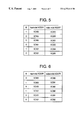
- FIG. 6 shows a routing table in the second embodiment of the present invention.
- FIG. 7 is a conceptual view of the procedures in the second embodiment of the present invention.
- FIG. 2 shows the structure of a routing device in which the routing system of the present invention is applied.
- packets and ATM cells are distributed between routes using a routing device (hereinbelow referred to as simply “node”) including a switch as shown in FIG. 2, a cross-connector, and other components.
- the node shown in FIG. 2 includes switch 101 , routing table 102 , route switch 103 , routing data base 104 , VCI (Virtual Channel Identifier) pool 105 , VCI consolidator 106 , and connecting information extractor 107 .
- VCI Virtual Channel Identifier
- FIG. 2 when packets belonging to a connection already set up are inputted, the inputted packets are copied to connecting information extractor 107 where header information is extracted, and then, the packets are switched at switch 101 .
- the header information extracted at connecting information extractor 107 is inputted to routing table 102 , and the switch destinations of inputted packets are communicated to switch 101 based on the header information.
- routing table 102 uses unused VCI numbers stored in VCI pool 105 at connections having set-up requests, and these VCI numbers are set to an “in use” state.
- VCI numbers used at the connection that is cut are set to an “unused” state in VCI pool 105 .
- connection set-up procedure of the ATM requires no special procedures other than those of the prior art.
- the present invention is distinguished by the mapping methods of the input cell ID and output cell ID in the routing table, and therefore, when setting up connections, any prior-art connection set-up procedure may be employed that stipulates a one-to-one mapping of input cell ID (input side VCI) and output cell ID (output-side VCI) in the routing table.
- UNI Spec. 3.1 stipulated by The ATM Forum is one example of such a connection set-up procedure.
- connections are set up one by one in succession when setting up a plurality of connections from source to destination.
- a set-up procedure that requires that the plurality of connections be set up simultaneously is also possible.
- the setting of routing tables at each node is carried out for each connection set-up request in the order of arrival.
- the first embodiment of the present invention relates to a routing table.
- FIG. 3 shows a routing table in the first embodiment of the present invention, and shows routing table 102 of the node shown in FIG. 2 .
- one input-side VCI inputted to switch 101 shown in FIG. 2 is mapped to one output-side VCI.
- the routing table of the first embodiment shown in FIG. 3, however, is constructed such that a plurality of input-side VCI are mapped to a single output-side VCI.
- FIG. 4 shows a conceptual view of the procedure of the first embodiment of the present invention, and presents a comparison of the results of setting up connections using the routing table shown in FIG. 3 and the results obtained using the routing table shown in FIG. 1 .
- the second embodiment of the present invention relates to a routing table and illustrates a case in which routes are switched based on an activity indicator.
- FIG. 5 and FIG. 6 show a routing table for the second embodiment of the present invention and a routing table 102 of the node shown in FIG. 2 .
- FIG. 5 shows the routing table for a node which used connection A and connection B of the same connection group.
- mapping of input-side and output-side VCI in the routing table shown in FIG. 5 is performed as follows.
- the value that is taken is determined by the ON or OFF state (corresponding to “1” and “0,” respectively, in FIG.
- AI activity indicator
- connection A an ON state of only one AI of the output-side VCI indicates that this output-side VCI is to be used, and OFF states of all of the AI of the remaining output-side VCI indicate that these output-side VCI are not to be used.
- connection B each output-side VCI for use by connection B has an AI, and the operation is equivalent to that of connection A.
- the switching of ON/OFF states of these AI is performed by route switch 103 shown in FIG. 2 .
- FIG. 6 shows a case in which, after consolidating the routes of a plurality of connections using the procedure described in the first embodiment, these routes are again branched using the procedure of the second embodiment.
- input-side VCI is the output-side VCI in the routing table described in the first embodiment, which is the output of the node of the preceding section.
- the value that is taken in input-side VCI is determined by the procedure described in the first embodiment in the routing table of the node of the preceding section.
- the ON state of only one AI of the output-side VCI for each input-side VCI indicates that this output-side VCI is to be used, and OFF states in all AI of the remaining output-side VCI indicate that these output-side VCI are not to be used.
- FIG. 7 is a conceptual view of the procedure in the second embodiment of the present invention.
- FIG. 7 (A) presents a comparison of the results of setting up connections using the routing table shown in FIG. 5 and the results of setting up connections using the routing table shown in FIG. 1 .
- FIG. 7 (B) shows a comparison of the results of setting up connections using the routing table shown in FIG. 6 and the results of setting up connections using the routing table shown in FIG. 1 .
- the third embodiment of the present invention shows a case in which AI of the routing table described in the second embodiment is set up indirectly according to congestive information of a network managed by a routing data base.
- Congestive information of a network described in the second embodiment can conceivably include such items as load, vacant bands, degree of congestion, cell loss rate, and cell delay times.
- an index indicating the load state of the network can also be used. Routes are selected based on these indices according to a procedure that is determined beforehand at route switch 103 . For example, a selection algorithm may be used by which routes having the lowest rate of use are selected.
- Route switch 103 selects the optimum route at each connection using any of the information contained within the information on congestion of the network that is extracted from routing data base 104 , which manages information indicating the congestive state of the network as the optimum routing information.
- Routing data base 104 may be any device that reflects the load state of the network.
- an ABR control procedure described in Draft specification ATM Forum 94-0471R8 of The ATM Forum (March 1995) discloses an ER rate within an RM cell designated for each connection, and this ER rate may be used as data indicating the congestive state of a route by which the RM cell was sent.
- the fourth embodiment of the present invention presents a case in which the AI of the routing table described in the second embodiment are set up using network congestive information held by the packets themselves.
- route switch 103 extracts some of the congestive information not from routing data base 104 described in the second embodiment, but from arriving packets, and based on this information, selects the optimum route for each connection. After determining routes, this determined routing is maintained as long as no information for route determination (route updating) is recorded in newly received packets.
- This congestive information may include such factors as load, vacant bands, degree of congestion, cell loss rate, and cell delay times.
- indices indicating load conditions in the network may also be used. These indices may be received from, for example, a network management system (NMS) by way of routing data base 104 . The route selection based on these indices is carried out according to a predetermined procedure at route switch 103 .
- NMS network management system
- an algorithm may be used that results in selection of routes in which no congestion occurs.
- the transmission terminal may designate which route is to selected based on these indices and record this information in packets to execute selection. Packets would be required to carry information indicating network congestive state or load conditions, and one possible method of conveying this information is, for example, to confer ER information to RM cells as described in Draft Specification ATM Forum 95-0013R8 of The ATM Forum (October 1995).
- the fifth embodiment of the present invention presents a case in which the AI of the routing table described in the second embodiment are set up using network connecting information held by the packets themselves.
- route switch 103 extracts information not from routing data base 104 described in the second embodiment, but from arriving packets.
- the extracted information is not congestive information described in the fourth embodiment, but connecting information.
- route switch 103 routes subsequent packets based on the extracted connecting information. This connecting information is designated at the time of transmitting information by the transmission terminal that is the source of transmitted information and recorded in the packets.
- Connecting information extractor 107 extracts this connecting information from arriving packets and forwards it to routing table 102 .
- the sixth embodiment of the present invention relates to the set-up procedure of the routing table described in the first embodiment.
- VCI consolidator 106 shown in FIG. 2 searches all connecting data of the routing table after obtaining input-side VCI and output-side VCI, and when a connection (connection B) is discovered in the same connection group as that set up for the next target node of the connection (connection A), changes the output-side VCI of connection A to the output-side VCI of connection B. In addition, it returns the output-side VCI number of connection A to VCI pool 105 , which manages unused output-side VCI numbers, and sets it to an unused state.
- VCI consolidator 106 operates immediately after setting up connection A
- the seventh embodiment of the present invention relates to the set-up procedure of the routing table described in the first embodiment.
- VCI consolidator 106 shown in FIG. 2 searches all connecting data of the routing table before obtaining input-side VCI and output-side VCI. Then, when a connection (connection B) is discovered in the same connection group as that set up for the next target node of the connection (connection A), VCI consolidator 106 makes the output-side VCI of connection A the same as the output-side VCI of connection B.
- the result is the same as the routing table shown in FIG. 3 .
Landscapes
- Engineering & Computer Science (AREA)
- Computer Networks & Wireless Communication (AREA)
- Signal Processing (AREA)
- Data Exchanges In Wide-Area Networks (AREA)
Applications Claiming Priority (2)
| Application Number | Priority Date | Filing Date | Title |
|---|---|---|---|
| JP1782196A JP2929993B2 (ja) | 1996-02-02 | 1996-02-02 | ルーティング方式 |
| JP8-017821 | 1996-02-02 |
Publications (1)
| Publication Number | Publication Date |
|---|---|
| US6272111B1 true US6272111B1 (en) | 2001-08-07 |
Family
ID=11954402
Family Applications (1)
| Application Number | Title | Priority Date | Filing Date |
|---|---|---|---|
| US08/792,380 Expired - Lifetime US6272111B1 (en) | 1996-02-02 | 1997-02-03 | Routing system |
Country Status (5)
| Country | Link |
|---|---|
| US (1) | US6272111B1 (fr) |
| EP (1) | EP0788259B1 (fr) |
| JP (1) | JP2929993B2 (fr) |
| CA (1) | CA2196140C (fr) |
| DE (1) | DE69737576D1 (fr) |
Cited By (5)
| Publication number | Priority date | Publication date | Assignee | Title |
|---|---|---|---|---|
| US20020019878A1 (en) * | 2000-08-11 | 2002-02-14 | Hironori Ochiai | Data transfer method and communication apparatus using the method |
| US20030072269A1 (en) * | 2001-10-11 | 2003-04-17 | Nippon Telegraph And Telephone Corporation | Data transmission control method, program therefor and data transmission unit using the same |
| EP1309219A1 (fr) * | 2001-10-31 | 2003-05-07 | Alcatel | Système, réseau, noeuds et méthode pour établir une liaison via messages d'établissement parallèles |
| US20040259595A1 (en) * | 2001-05-30 | 2004-12-23 | Ganghua Yang | Method for implementing speech channel exchange in the call succession of the mobile communication system |
| US6891795B1 (en) * | 2000-01-31 | 2005-05-10 | Fujitsu Limited | Node device |
Families Citing this family (3)
| Publication number | Priority date | Publication date | Assignee | Title |
|---|---|---|---|---|
| JP2002044138A (ja) | 2000-07-25 | 2002-02-08 | Nec Corp | ネットワークシステム,キャッシュサーバ,中継サーバ,ルータ,キャッシュサーバ制御方法及び記録媒体 |
| JP3931910B2 (ja) * | 2005-04-28 | 2007-06-20 | 日本電気株式会社 | ネットワークシステム、キャッシュサーバ、キャッシュサーバ制御方法及び記録媒体 |
| JP3925542B2 (ja) * | 2005-04-28 | 2007-06-06 | 日本電気株式会社 | ネットワークシステム、キャッシュサーバ、キャッシュサーバの制御方法、プログラムを記録した記録媒体 |
Citations (10)
| Publication number | Priority date | Publication date | Assignee | Title |
|---|---|---|---|---|
| JPH01101756A (ja) | 1987-10-15 | 1989-04-19 | Oki Electric Ind Co Ltd | 交換方式 |
| EP0538853A2 (fr) | 1991-10-22 | 1993-04-28 | Fujitsu Limited | Commande distribuée d'un réseau de communication pour établir une voie de communication alternative |
| JPH0638257A (ja) | 1992-07-20 | 1994-02-10 | Nec Corp | 交換機の回線選択方式 |
| JPH06205077A (ja) | 1992-12-28 | 1994-07-22 | Toshiba Corp | 通信制御装置 |
| EP0645918A2 (fr) | 1993-09-16 | 1995-03-29 | Siemens Aktiengesellschaft | Procédé et dispositif de circuit pour la transmission de cellules de messages par les paires de voies redondantes virtuelles d'un réseau de communication ATM |
| JPH07131456A (ja) | 1993-11-04 | 1995-05-19 | Fujitsu Ltd | 通信網の分散型経路選択制御装置 |
| EP0683619A2 (fr) | 1994-05-11 | 1995-11-22 | Siemens Aktiengesellschaft | Méthode et appareil pour la déviation d'un courant de cellules de communication sur une voie alternative |
| US5513178A (en) * | 1993-05-19 | 1996-04-30 | Fujitsu Limited | Cell multiplexing apparatus in ATM network |
| US5715237A (en) * | 1994-12-28 | 1998-02-03 | Fujitsu Limited | Inter digital switching equipment relay system and digital switching equipment |
| US5963863A (en) * | 1995-12-01 | 1999-10-05 | Telefonaktiebolaget L M Ericsson | Routing system for automatically routing a call to a multi-mode transceiver in a wireless network |
-
1996
- 1996-02-02 JP JP1782196A patent/JP2929993B2/ja not_active Expired - Fee Related
-
1997
- 1997-01-28 CA CA 2196140 patent/CA2196140C/fr not_active Expired - Fee Related
- 1997-01-31 DE DE69737576T patent/DE69737576D1/de not_active Expired - Lifetime
- 1997-01-31 EP EP19970101628 patent/EP0788259B1/fr not_active Expired - Lifetime
- 1997-02-03 US US08/792,380 patent/US6272111B1/en not_active Expired - Lifetime
Patent Citations (10)
| Publication number | Priority date | Publication date | Assignee | Title |
|---|---|---|---|---|
| JPH01101756A (ja) | 1987-10-15 | 1989-04-19 | Oki Electric Ind Co Ltd | 交換方式 |
| EP0538853A2 (fr) | 1991-10-22 | 1993-04-28 | Fujitsu Limited | Commande distribuée d'un réseau de communication pour établir une voie de communication alternative |
| JPH0638257A (ja) | 1992-07-20 | 1994-02-10 | Nec Corp | 交換機の回線選択方式 |
| JPH06205077A (ja) | 1992-12-28 | 1994-07-22 | Toshiba Corp | 通信制御装置 |
| US5513178A (en) * | 1993-05-19 | 1996-04-30 | Fujitsu Limited | Cell multiplexing apparatus in ATM network |
| EP0645918A2 (fr) | 1993-09-16 | 1995-03-29 | Siemens Aktiengesellschaft | Procédé et dispositif de circuit pour la transmission de cellules de messages par les paires de voies redondantes virtuelles d'un réseau de communication ATM |
| JPH07131456A (ja) | 1993-11-04 | 1995-05-19 | Fujitsu Ltd | 通信網の分散型経路選択制御装置 |
| EP0683619A2 (fr) | 1994-05-11 | 1995-11-22 | Siemens Aktiengesellschaft | Méthode et appareil pour la déviation d'un courant de cellules de communication sur une voie alternative |
| US5715237A (en) * | 1994-12-28 | 1998-02-03 | Fujitsu Limited | Inter digital switching equipment relay system and digital switching equipment |
| US5963863A (en) * | 1995-12-01 | 1999-10-05 | Telefonaktiebolaget L M Ericsson | Routing system for automatically routing a call to a multi-mode transceiver in a wireless network |
Non-Patent Citations (2)
| Title |
|---|
| H. Suzuki et al., "Fast Bandwidth Reservation Scheme with Multi-Link & Multi-Path Routing in ATM Networks", IEEE Communications Society, Reprint, Dec. 2-5, 1991, pp. 2233-2240. |
| Sallbeerg K. et al. "ATM Traffic Management at the Initial Depolyment of B-ISDN" Ericsson Review, SE, Ericsson. Stockholm, vol. 71, No. 4, 1994, pp. 150-159. |
Cited By (7)
| Publication number | Priority date | Publication date | Assignee | Title |
|---|---|---|---|---|
| US6891795B1 (en) * | 2000-01-31 | 2005-05-10 | Fujitsu Limited | Node device |
| US20020019878A1 (en) * | 2000-08-11 | 2002-02-14 | Hironori Ochiai | Data transfer method and communication apparatus using the method |
| US6865182B2 (en) * | 2000-08-11 | 2005-03-08 | Fujitsu Limited | Data transfer method including recognizing identical messages and communication apparatus using the method |
| US20040259595A1 (en) * | 2001-05-30 | 2004-12-23 | Ganghua Yang | Method for implementing speech channel exchange in the call succession of the mobile communication system |
| US20030072269A1 (en) * | 2001-10-11 | 2003-04-17 | Nippon Telegraph And Telephone Corporation | Data transmission control method, program therefor and data transmission unit using the same |
| US7327676B2 (en) * | 2001-10-11 | 2008-02-05 | Nippon Telegraph And Telephone Corporation | Data transmission control method, program therefor and data transmission unit using the same |
| EP1309219A1 (fr) * | 2001-10-31 | 2003-05-07 | Alcatel | Système, réseau, noeuds et méthode pour établir une liaison via messages d'établissement parallèles |
Also Published As
| Publication number | Publication date |
|---|---|
| JPH09214509A (ja) | 1997-08-15 |
| JP2929993B2 (ja) | 1999-08-03 |
| EP0788259A2 (fr) | 1997-08-06 |
| EP0788259A3 (fr) | 2001-02-14 |
| EP0788259B1 (fr) | 2007-04-11 |
| CA2196140C (fr) | 2002-09-17 |
| DE69737576D1 (de) | 2007-05-24 |
| CA2196140A1 (fr) | 1997-08-03 |
Similar Documents
| Publication | Publication Date | Title |
|---|---|---|
| US7463633B2 (en) | Packet switching system, packet switching network and packet switching method | |
| US6147999A (en) | ATM switch capable of routing IP packet | |
| US6717920B1 (en) | Dynamically created service class-based routing tables | |
| EP0512495B1 (fr) | Noeud de commutation dans un réseau d'information multiplexé contenant une étiquette | |
| US5453981A (en) | Method of controlling communication network incorporating virtual channels exchange nodes and virtual paths exchange nodes | |
| US6081506A (en) | Integrating switching and facility networks using ATM | |
| JP4368981B2 (ja) | Atmネットワーク中のロード平衡したubrルーティング | |
| EP1235461A2 (fr) | Procedé de contrôle d'admission et d' acheminement des circuits virtuels | |
| US6587436B1 (en) | Method and apparatus for allocation of available bandwidth | |
| US20010056553A1 (en) | Method and system for routing packets without losing packets by monitoring outgoing lines | |
| US6272111B1 (en) | Routing system | |
| US5748632A (en) | ATM switching apparatus | |
| US5444699A (en) | Call and connection set up system in transmission network | |
| US6515998B1 (en) | Table data retrieving apparatus retrieving table in which reference data is stored by using retrieval key | |
| US6563811B2 (en) | Routing decision in connection-oriented packet network | |
| JPH11127173A (ja) | 接続群を有するatmセル切換装置およびatmセル切換方法と、対応する入出力端末手段 | |
| EP0481447A2 (fr) | Méthode de commande d'un réseau de communication incluant des noeuds de commutations de canaux virtuels et des noeuds de commutation de chemin virtuel | |
| KR19990087607A (ko) | Atm 네트워크를 통한 atm 셀의 전송 방법 | |
| JP3349988B2 (ja) | Atm網における迂回ルートからの自動切り戻し方法およびシステム | |
| JP2000349770A (ja) | Atmにおけるipパケットルーティングプロセッサの分散処理方法及びその装置 | |
| Onvural et al. | Routing in ATM networks | |
| JP3327446B2 (ja) | Atm通信網 | |
| KR0175485B1 (ko) | 완전 분산형 비동기전달모드 교환 시스템에서 재시도를 이용한 경로 제어 방법 | |
| KR100281411B1 (ko) | 점대 다중점 가용 비트율 서비스를 위한 역방향 자원관리 셀의통합방법 | |
| Takahashi et al. | B-ISDN networking using group virtual paths |
Legal Events
| Date | Code | Title | Description |
|---|---|---|---|
| AS | Assignment |
Owner name: NEC CORPORATION, JAPAN Free format text: ASSIGNMENT OF ASSIGNORS INTEREST;ASSIGNOR:MURASE, TUTOMU;REEL/FRAME:008452/0142 Effective date: 19970120 |
|
| STCF | Information on status: patent grant |
Free format text: PATENTED CASE |
|
| FEPP | Fee payment procedure |
Free format text: PAYOR NUMBER ASSIGNED (ORIGINAL EVENT CODE: ASPN); ENTITY STATUS OF PATENT OWNER: LARGE ENTITY |
|
| FPAY | Fee payment |
Year of fee payment: 4 |
|
| FPAY | Fee payment |
Year of fee payment: 8 |
|
| FPAY | Fee payment |
Year of fee payment: 12 |