US6330810B1 - Condensing apparatus for use in a refrigeration cycle receiver-dryer used for said condensing apparatus - Google Patents
Condensing apparatus for use in a refrigeration cycle receiver-dryer used for said condensing apparatus Download PDFInfo
- Publication number
- US6330810B1 US6330810B1 US09/716,397 US71639700A US6330810B1 US 6330810 B1 US6330810 B1 US 6330810B1 US 71639700 A US71639700 A US 71639700A US 6330810 B1 US6330810 B1 US 6330810B1
- Authority
- US
- United States
- Prior art keywords
- refrigerant
- passage
- main body
- tank main
- discharging
- Prior art date
- Legal status (The legal status is an assumption and is not a legal conclusion. Google has not performed a legal analysis and makes no representation as to the accuracy of the status listed.)
- Expired - Lifetime
Links
Images


Classifications
-
- B—PERFORMING OPERATIONS; TRANSPORTING
- B60—VEHICLES IN GENERAL
- B60H—ARRANGEMENTS OF HEATING, COOLING, VENTILATING OR OTHER AIR-TREATING DEVICES SPECIALLY ADAPTED FOR PASSENGER OR GOODS SPACES OF VEHICLES
- B60H1/00—Heating, cooling or ventilating devices
- B60H1/32—Cooling devices
- B60H1/3204—Cooling devices using compression
- B60H1/3229—Cooling devices using compression characterised by constructional features, e.g. housings, mountings, conversion systems
-
- F—MECHANICAL ENGINEERING; LIGHTING; HEATING; WEAPONS; BLASTING
- F25—REFRIGERATION OR COOLING; COMBINED HEATING AND REFRIGERATION SYSTEMS; HEAT PUMP SYSTEMS; MANUFACTURE OR STORAGE OF ICE; LIQUEFACTION SOLIDIFICATION OF GASES
- F25B—REFRIGERATION MACHINES, PLANTS OR SYSTEMS; COMBINED HEATING AND REFRIGERATION SYSTEMS; HEAT PUMP SYSTEMS
- F25B43/00—Arrangements for separating or purifying gases or liquids; Arrangements for vaporising the residuum of liquid refrigerant, e.g. by heat
-
- B—PERFORMING OPERATIONS; TRANSPORTING
- B60—VEHICLES IN GENERAL
- B60H—ARRANGEMENTS OF HEATING, COOLING, VENTILATING OR OTHER AIR-TREATING DEVICES SPECIALLY ADAPTED FOR PASSENGER OR GOODS SPACES OF VEHICLES
- B60H1/00—Heating, cooling or ventilating devices
- B60H1/32—Cooling devices
- B60H1/3204—Cooling devices using compression
- B60H1/3227—Cooling devices using compression characterised by the arrangement or the type of heat exchanger, e.g. condenser, evaporator
-
- F—MECHANICAL ENGINEERING; LIGHTING; HEATING; WEAPONS; BLASTING
- F25—REFRIGERATION OR COOLING; COMBINED HEATING AND REFRIGERATION SYSTEMS; HEAT PUMP SYSTEMS; MANUFACTURE OR STORAGE OF ICE; LIQUEFACTION SOLIDIFICATION OF GASES
- F25B—REFRIGERATION MACHINES, PLANTS OR SYSTEMS; COMBINED HEATING AND REFRIGERATION SYSTEMS; HEAT PUMP SYSTEMS
- F25B39/00—Evaporators; Condensers
- F25B39/04—Condensers
-
- F—MECHANICAL ENGINEERING; LIGHTING; HEATING; WEAPONS; BLASTING
- F25—REFRIGERATION OR COOLING; COMBINED HEATING AND REFRIGERATION SYSTEMS; HEAT PUMP SYSTEMS; MANUFACTURE OR STORAGE OF ICE; LIQUEFACTION SOLIDIFICATION OF GASES
- F25B—REFRIGERATION MACHINES, PLANTS OR SYSTEMS; COMBINED HEATING AND REFRIGERATION SYSTEMS; HEAT PUMP SYSTEMS
- F25B43/00—Arrangements for separating or purifying gases or liquids; Arrangements for vaporising the residuum of liquid refrigerant, e.g. by heat
- F25B43/003—Filters
-
- F—MECHANICAL ENGINEERING; LIGHTING; HEATING; WEAPONS; BLASTING
- F25—REFRIGERATION OR COOLING; COMBINED HEATING AND REFRIGERATION SYSTEMS; HEAT PUMP SYSTEMS; MANUFACTURE OR STORAGE OF ICE; LIQUEFACTION SOLIDIFICATION OF GASES
- F25B—REFRIGERATION MACHINES, PLANTS OR SYSTEMS; COMBINED HEATING AND REFRIGERATION SYSTEMS; HEAT PUMP SYSTEMS
- F25B2339/00—Details of evaporators; Details of condensers
- F25B2339/04—Details of condensers
- F25B2339/044—Condensers with an integrated receiver
- F25B2339/0441—Condensers with an integrated receiver containing a drier or a filter
-
- F—MECHANICAL ENGINEERING; LIGHTING; HEATING; WEAPONS; BLASTING
- F25—REFRIGERATION OR COOLING; COMBINED HEATING AND REFRIGERATION SYSTEMS; HEAT PUMP SYSTEMS; MANUFACTURE OR STORAGE OF ICE; LIQUEFACTION SOLIDIFICATION OF GASES
- F25B—REFRIGERATION MACHINES, PLANTS OR SYSTEMS; COMBINED HEATING AND REFRIGERATION SYSTEMS; HEAT PUMP SYSTEMS
- F25B2339/00—Details of evaporators; Details of condensers
- F25B2339/04—Details of condensers
- F25B2339/044—Condensers with an integrated receiver
- F25B2339/0446—Condensers with an integrated receiver characterised by the refrigerant tubes connecting the header of the condenser to the receiver; Inlet or outlet connections to receiver
-
- F—MECHANICAL ENGINEERING; LIGHTING; HEATING; WEAPONS; BLASTING
- F25—REFRIGERATION OR COOLING; COMBINED HEATING AND REFRIGERATION SYSTEMS; HEAT PUMP SYSTEMS; MANUFACTURE OR STORAGE OF ICE; LIQUEFACTION SOLIDIFICATION OF GASES
- F25B—REFRIGERATION MACHINES, PLANTS OR SYSTEMS; COMBINED HEATING AND REFRIGERATION SYSTEMS; HEAT PUMP SYSTEMS
- F25B2500/00—Problems to be solved
- F25B2500/01—Geometry problems, e.g. for reducing size
-
- F—MECHANICAL ENGINEERING; LIGHTING; HEATING; WEAPONS; BLASTING
- F25—REFRIGERATION OR COOLING; COMBINED HEATING AND REFRIGERATION SYSTEMS; HEAT PUMP SYSTEMS; MANUFACTURE OR STORAGE OF ICE; LIQUEFACTION SOLIDIFICATION OF GASES
- F25B—REFRIGERATION MACHINES, PLANTS OR SYSTEMS; COMBINED HEATING AND REFRIGERATION SYSTEMS; HEAT PUMP SYSTEMS
- F25B40/00—Subcoolers, desuperheaters or superheaters
- F25B40/02—Subcoolers
Definitions
- This invention relates to a condensing apparatus for use in a refrigeration cycle applied to an air-conditioning system for automobiles, buildings, etc., and also relates to a receiver-dryer used for such a condensing apparatus.
- FIG. 6 shows an expansion-valve system refrigeration cycle as one of typical refrigeration cycles.
- the gaseous refrigerant of high temperature and high pressure sent out from a compressor CP is introduced into a condenser CD and exchanges heat with the ambient air to be cooled and condensed therein.
- the condensed refrigerant mostly in a liquefied state flows into a receiver-tank RT to be separated into a gaseous refrigerant and a liquefied refrigerant. Then, only the liquefied refrigerant flows out of the receiver-tank RT.
- the liquefied refrigerant is decompressed and expanded by an expansion-valve EV, and is introduced into an evaporator EP as a mist-like refrigerant of low pressure and low temperature.
- This mist-like refrigerant evaporates in the evaporator EP by absorbing latent heat from the ambient air to be turned into a gaseous refrigerant. Then, the gaseous refrigerant flows out of the evaporator EP, and is inhaled by the compressor CP.
- the spotted area indicates that a refrigerant is in a liquid state.
- the refrigeration flow rate is controlled by adjusting the opening degree of the expansion-valve EV in response to the signal sent from the heat-sensitive-coupler SC provided at the outlet side of the evaporator EP.
- a subcooling portion which subcools the refrigerant condensed by the condenser CD to a temperature lower than the condensation temperature of the refrigerant by about 2-5° C., is provided so as to send the condensed refrigerant to the evaporator side as a stabilized liquid refrigerant.
- this subcooling portion is arranged at the downstream side of the receiver-tank RT. In many cases, such a subcooling portion is integrally provided to the condenser CD in view of the space efficiency.
- a receiver-dryer is used as the aforementioned receiver-tank RT.
- the receiver-dryer is provided with a desiccant-filled-portion therein to absorb the moisture components of the refrigerant.
- Such a receiver-dryer includes the so-called sandwich-type receiver-dryer having an upper space 33 above a desiccant-filled portion 32 and a lower space 34 below the desiccant-filled portion 32 as shown in FIGS. 8A-8C and the so-called bag-type receiver-dryer provided with a desiccant-filled portion 32 in one side therein as shown in FIG. 8 D.
- the refrigerant flowed into the upper space 33 via the refrigerant inlet 35 passes through the desiccant-filled-portion 32 to reach the lower space 34 . Then, the liquefied refrigerant separated from the gaseous refrigerant is sucked up by the sucking-pipe 36 and flows out from the refrigerant outlet 37 provided at the top of the tank.
- the refrigerant introduced from the refrigerant inlet 35 provided at the bottom portion flows up the supplying-pipe 38 to reach the upper space 33 , and then passes through the desiccant-filled-portion 32 to reach the lower space 34 . Then, the liquefied refrigerant separated from the gaseous refrigerant flows out from the refrigerant outlet 37 provided at the bottom of the tank.
- the refrigerant introduced into the upper space 33 via the top refrigerant inlet 35 passes through the desiccant-filled-portion 32 to reach the lower space 34 . Then, the liquefied refrigerant separated from the gaseous refrigerant flows out from the refrigerant outlet 37 provided at the bottom of the tank.
- this bag-type receiver-dryer there are a receiver-dryer having an outlet and an inlet both provided at an upper portion or a lower portion of a tank and a receiver-dryer having an outlet and an inlet provided at an upper portion and a lower portion of a tank, respectively.
- FIG. 7 is a correlation characteristic figure showing the correlation between a subcooling degree of the condensed refrigerant and an amount of sealed refrigerant obtained by a charge examination (cycle bench) of an automobile air-conditioner.
- this correlation characteristic figure it is ideal that the rising curve is steep until it reaches a steady region as shown by the phantom-line curve B and that the steady region has a wider range.
- the rising curve is gentle until it reaches the steady region as shown by the solid-line curve A. Therefore, the steady region starting point delays toward the larger amount of a sealed refrigerant side, which results in a delayed refrigerant sealing timing and a narrow steady region width. This means that in the conventional automobile air-conditioner the miniaturization by decreasing the sealed refrigerant amount is difficult, the performance stability to load fluctuation is bad, and the performance tends to deteriorate with time due to continuous running.
- the inventors further conducted the researches based on the above-mentioned knowledge, and found out the followings and completed the present invention. That is, an adoption of a specific structure of a receiver-dryer stabilizes a surface of a liquefied refrigerant separated from a gaseous refrigerant near a refrigerant outlet, which enables a stable supply of the liquefied refrigerant to the following cycle part.
- bubbles of a gaseous refrigerant smoothly change to a gaseous refrigerant at the interface of the gaseous refrigerant and the liquefied refrigerant, and the mixing of the gaseous refrigerant into the liquefied refrigerant to be flowed out is decreased effectively.
- This enables a decreased amount of sealed refrigerant of a refrigeration cycle, and an enlarged steady region of the refrigerant to the amount of sealed refrigerant making the best use of the capacity of the receiver-dryer. Consequently, it is possible to provide a condensing apparatus suitably used for an automobile air-conditioner using a subcooling system condenser.
- An object of the present invention is to provide a condensing apparatus for use in a refrigeration cycle in which a surface of a liquefied refrigerant separated from a gaseous refrigerant can be stabilized and only the liquefied refrigerant can be supplied from the receiver-dryer to the subsequent cycle part.
- Another object of the present invention is to provide a receiver-dryer used for the above-mentioned condensing apparatus in which the surface of the liquefied refrigerant separated from the gaseous refrigerant can be stabilized and only the liquefied refrigerant can be supplied to the subsequent cycle part.
- a condensing apparatus includes a condenser having a condensing portion for condensing a gaseous refrigerant and a receiver-dryer which receives the condensed refrigerant condensed by the condensing portion of the condenser, separates the condensed refrigerant into a gaseous refrigerant and a liquefied refrigerant, and removes moisture contained in the condensed refrigerant
- the receiver-dryer includes a tank main body, a desiccant-filled-portion arranged so that an upper space is formed in the tank main portion at an upper part of the tank main body, a refrigerant-introducing-passage for introducing the condensed refrigerant into the tank main body from the condenser, and a refrigerant-discharging-passage for discharging the liquefied refrigerant in the tank main body, wherein the refrigerant-introducing-passage
- a receiver-dryer is arranged at a downstream side of a condensing portion of a condenser in a refrigeration cycle to receive a condensed refrigerant condensed by the condensing portion of the condenser, separate the condensed refrigerant into a gaseous refrigerant and a liquefied refrigerant and remove moisture contained in the condensed refrigerant.
- the receiver-dryer includes a tank main body, a desiccant-filled-portion arranged so that an upper space is formed at an upper part in the tank main body, a refrigerant-introducing-passage for introducing the condensed refrigerant into the tank main body from the condenser, and a refrigerant-discharging-passage for discharging the liquefied refrigerant in the tank main body.
- the refrigerant-introducing-passage has an outlet which opens toward an inner bottom side of the tank main body.
- the refrigerant-discharging-passage penetrates the desiccant-filled-portion and has an inlet formed so as to open toward the upper space at an upper end of the desiccant-filled-portion and an outlet formed at a bottom portion of the tank main body.
- the condensed refrigerant is introduced into an inner bottom of the tank main body through the outlet of the refrigerant-introducing-passage from the condensing portion of the condenser, and passes through the desiccant-filled-portion upward to be accumulated in the upper space, and the accumulated liquefied refrigerant is introduced into the inlet of the refrigerant-discharging-passage and flows out of the tank main body via the outlet.
- the refrigerant which is a mixture of a gaseous refrigerant and a liquefied refrigerant sent to the receiver-dryer from the condenser, is abruptly diffused at the outlet of the refrigerant-introducing-passage into a wide area of the inner bottom portion of the tank main body to thereby reduce the flow velocity. Subsequently, the refrigerant goes up through the desiccant-filled-portion. At this time, the desiccant-filled-portion functions as a resistance layer which reduces the refrigerant flow velocity.
- the liquefied refrigerant which is slow in flow velocity as compared with a gaseous refrigerant, passes through the desiccant-filled-portion to reach the upper space, which causes a reduced flow velocity. Accordingly, the liquefied refrigerant accumulates in the upper space without causing turbulence.
- the flow velocity of the gaseous refrigerant also abruptly reduces when the gaseous refrigerant passes through the desiccant-filled-portion. For this reason, when the gaseous refrigerant reaches the accumulated liquefied refrigerant accumulated in the upper space, it slowly goes up in the liquefied refrigerant as bubbles.
- the condensing apparatus may further includes a subcooling portion which subcools the refrigerant condensed by the condensing portion of the condenser, wherein the outlet of the condensing portion of the condenser is connected to the inlet of the refrigerant-introducing-passage of the receiver-dryer, and wherein the outlet of the refrigerant-discharging-passage of the receiver-dryer is connected to the inlet of the subcooling portion.
- the subcooling portion since only the liquefied refrigerant is stably supplied to the subcooling portion from the receiver-dryer, the subcool function by the subcooling portion can be demonstrated to the maximum extent, and thus a sufficient subcool region can be secured.
- the subcooling portion may be integrally provided at a downstream side of the condensing portion of the condenser.
- the inlet of the refrigerant-discharging-passage has an enlarged-diameter-portion having a diameter enlarging toward the upper space.
- the inlet of the refrigerant-discharging-passage serves as a dented portion at the upper end of the desiccant-filled-portion, the liquefied refrigerant easily flows into the refrigerant-discharging-passage.
- the flow velocity at the enlarged-diameter-portion is lower than that at the inner side of the non-enlarged-diameter-portion, even if bubbles of the gaseous refrigerant appear near the inlet, the bubbles easily go upward in the enlarged-diameter-portion.
- the inner diameter of the non-enlarged-diameter-portion of the inlet of the refrigerant-discharging-passage, the maximum opening diameter of the enlarged-diameter-portion and the depth of the enlarged-diameter-portion are defined by d 1 , d 2 and h 1 , respectively.
- the inlet of the refrigerant-discharging-passage may have a cylindrical bubble-swallow-prevention wall extending upward from the upper end of the enlarged-diameter-portion.
- the bubbles of the gaseous refrigerant going up through the accumulated liquefied refrigerant in the upper space becomes hard to be involved into the liquefied refrigerant flowing toward the outlet, resulting in a decrease amount of gaseous refrigerant flowed into the refrigerant-discharging-passage.
- the distance between the center of the refrigerant-introducing-passage and the center of the refrigerant-discharging-passage, the inner diameter of the tank main body and the opening diameter of the outlet of the refrigerant-introducing-passage are defined by L 1 , D and ⁇ , respectively.
- the opening center of the refrigerant-introducing-passage and the outlet center of the refrigerant-discharging-passage are moderately apart from each other, the upstream flow of the refrigerant introduced from the refrigerant-introducing-passage will not concentrate on the inlet side of the refrigerant-discharging-passage and the refrigerant flow velocity sufficiently decreases.
- the refrigerant surface can be further stabilized.
- a vertical length of the desiccant-filled-portion and an effective vertical length of the tank main body are defined by Ld and Le, respectively.
- Ld and Le a sufficient space for accumulating the liquefied refrigerant and the gaseous refrigerant in the upper part of the tank main body can be secured. Therefore, the stable region of the refrigerant to the amount of sealed refrigerant can be enlarged by fully using the capacity of the receiver-dryer.
- a space is formed between the lower end of the desiccant-filled-portion and the inner bottom of the tank main body and the space has a vertical height of 25% or less of the vertical length of the desiccant-filled-portion.
- the refrigerant flowed from the refrigerant-introducing-port can be smoothly diffused, resulting in an enhanced flow velocity drop functions by the diffusion, which forms further stabilized interface between the gaseous refrigerant and the liquefied refrigerant.
- the lower space is small, a turbulent flow region is hard to be produced and there is no room to generate a large amount of accumulated liquefied refrigerant, which enables a sufficient supply of the liquefied refrigerant to the upper space.
- the desiccant-filled-portion includes a pair of porous dividing walls arranged at a predetermined interval, a dryer including spherical particles filled up between the porous dividing walls and a filter arranged between the dryer and at least one of the porous dividing walls.
- the refrigerant going up through the desiccant-filled-portion passes through among the spherical particles while changing its direction frequently, it follows a long course. Therefore, the flow velocity of the refrigerant decreases remarkably and a local high-speed refrigerant flow disappears by the rectification function, which causes an equalized upstream flow as a whole.
- the liquefied refrigerant and the gaseous refrigerant are finely dispersed by the rectification functions of the filter, the accumulated liquefied refrigerant can be further stabilized in the upper space.
- FIG. 1 is a front view showing an embodiment of a condensing apparatus in a refrigeration cycle according to the present invention
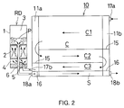
- FIG. 2 is a vertical front view showing the flow of the refrigerant in the condensing apparatus
- FIG. 3 is an enlarged vertical cross-sectional front view of the receiver-dryer of the condensing apparatus
- FIG. 4 is a schematic vertical cross-sectional front view showing the size relation of each part of the receiver-dryer
- FIG. 5A is a schematic vertical cross-sectional front view of the principal portion of a modification of the receiver-dryer
- FIG. 5B is a schematic vertical cross-sectional front view of the principal portion of another modification of the receiver-dryer
- FIG. 6 is a refrigerant circuit diagram of a refrigeration cycle
- FIG. 7 is a correlation characteristic figure showing the correlation between a subcooling degree of a condensed refrigerant and an amount of sealed refrigerant;
- FIG. 8A is a schematic vertical cross-sectional view of a conventional sucking-pipe-type receiver-dryer
- FIG. 8B is a schematic vertical cross-sectional view of a conventional supplying-pipe-type receiver-dryer
- FIG. 8C is a schematic vertical cross-sectional view of a conventional inlet-outlet-confrontation-type receiver-dryer.
- FIG. 8D is a schematic vertical cross-sectional view of a conventional bag-type receiver-dryer.
- FIG. 1 is a front view of a condensing apparatus.
- FIG. 2 is a vertical cross-sectional front view showing the refrigerant flow in the condensing apparatus.
- FIG. 3 is an enlarged vertical cross-sectional front view of the receiver-dryer of the condensing apparatus.
- FIG. 4 is a schematic vertical cross-sectional front view showing the size relation of each part of the receiver-dryer.
- FIG. 1 shows a subcooling system condenser 10 .
- the condenser 10 includes a condensing portion C and a subcooling portion S integrally provided to the condensing portion C.
- This condenser 10 is provided with a pair of right and left vertical headers 11 a and 11 b spaced apart from each other and a plurality of flat heat exchanging tubes 12 disposed horizontally between the headers 11 a and 11 b at certain intervals with both ends of thereof being communicated with the corresponding headers 11 a and 11 b.
- a corrugated fin 13 is arranged on the outside of each outermost heat exchanging tube 12 . Between the adjacent heat exchanging tubes 12 and 12 , corrugated fins 13 are arranged.
- a side plate 14 for protecting the corrugated fin 13 is arranged on the outside of each outermost heat exchanging tube 12 .
- each header 11 a and 11 b partition members 16 each for dividing the inside of the header are provided at the same height.
- the upper side of the condenser 10 above the partition members 16 and 16 and the lower side thereof below the partition members 16 and 16 constitute a condensing portion C and a subcooling portion S, respectively.
- the condensing portion C the aforementioned plurality of tubular elements 12 are divided into the first pass C 1 to the third pass C 3 by partition members 15 and 15 provided in the headers 11 a and 11 b at predetermined positions.
- a condensing portion inlet 17 a and a subcooling portion outlet 18 b are provided, respectively.
- a condensing portion outlet 17 b and a subcooling portion inlet 18 a are provided, respectively.
- a receiver-dryer RD is attached to the left-hand header 11 a along the header 11 a.
- this receiver-dryer RD is equipped with a tank main body 1 of a vertical cylindrical type.
- a desiccant-filled-portion 2 is provided at the longitudinal central portion of the tank main body 1 to form an upper space 3 above the desiccant-filled-portion 2 and a lower space 4 below the desiccant-filled-portion 2 .
- a refrigerant-introducing-passage 5 is provided at the position apart from the center of the bottom wall 1 a of the tank main body 1 such that the outlet 5 a of the refrigerant-introducing-passage 5 opens toward the lower space 4 .
- the pipe 60 disposed along the central axis of the tank main body 1 constitutes a refrigerant-discharging-passage 6 .
- the refrigerant-discharging-passage 6 has an inlet 6 a which opens toward the upper space 3 at the upper end central portion of the desiccant-filled-portion 2 .
- the refrigerant-discharging-passage 6 extends along the central axis of the tank main body 1 and penetrates the central portion of the bottom wall 1 a to be communicated with the exterior of the tank main body 1 .
- the inlet 6 a has an enlarged-diameter-portion 61 in the shape of a bell which opens toward the upper space 3 .
- the desiccant-filled-portion 2 includes upper and lower porous plates 21 a and 21 b and spherical desiccant particles 2 a filled between the plates 21 a and 21 b . Between the upper porous plate 21 a and the top of the filled spherical desiccant particles 2 a , a filter 7 made of fine porous materials is disposed.
- the inlet 5 b of the refrigerant-introducing-passage 5 of the receiver-dryer RD is connected to the condensing portion outlet 17 b of the subcooling system condenser 10 .
- the outlet 6 b of the refrigerant-discharging passage 6 is communicated with the subcooling portion inlet 18 a via an L-shaped pipe 19 .
- the gaseous refrigerant of high temperature and high pressure from the compressor CP of the refrigeration cycle is introduced into the condensing portion C via the condensing portion inlet 17 a of the subcooling system condenser 10 .
- the gaseous refrigerant passes through the first pass C 1 to the third pass C 3 in turn.
- the gaseous refrigerant exchanges heat with the ambient air to be condensed, and flows into the receiver dryer RD via the condensing portion outlet 17 b as a mixture of a gaseous refrigerant and a liquefied refrigerant.
- the refrigerant which is a mixture of a gaseous refrigerant and a liquefied refrigerant, is separated into the gaseous refrigerant and the liquefied refrigerant in the receiver-dryer RD. Then, the liquefied refrigerant passes through the refrigerant-discharging-passage 6 and flows into the subcooling portion S via the subcooling portion inlet 18 a . In the subcooling portion S, the liquefied refrigerant further exchanges heat with the ambient air to be subcooled. The subcooled refrigerant is then sent to the following cycle part (an evaporator side) via the subcooling portion outlet 18 b.
- the refrigerant which is a mixture of a gaseous refrigerant and a liquefied refrigerant sent from the condensing portion C of the subcooling system condenser 10 , is sent into the receiver-dryer RD at a high flow velocity.
- the refrigerant flows into the lower space 4 through the refrigerant-introducing-passage 5 , it diffuses widely, resulting in a decreased flow velocity.
- the desiccant-filled-portion 2 functions as a resistance layer to the refrigeration flow going up through the desiccant-filled-portion 2 , the upstream flow velocity is reduced remarkably and the refrigerant slowly flows into the upper space 3 .
- the refrigerant passing through the spherical particles 2 a of the desiccant-filled-portion 2 changes its direction frequently to take a long course. Therefore, the flow velocity reduces remarkably and a local high velocity flow also disappears due to the rectification function, resulting in an uniform upstream flow. Moreover, when passing through the filter 7 , the liquefied refrigerant and the gaseous refrigerant will be dispersed finely.
- the liquefied refrigerant which is slow in flow velocity as compared with a gaseous refrigerant, passes through the desiccant-filled-portion 2 to reach an upper space 3 , which results in a further reduced flow velocity. Accordingly, the liquefied refrigerant P accumulates in the upper space 3 without causing turbulence.
- the flow velocity of the gaseous refrigerant is also abruptly reduced when the gaseous refrigerant passes through the desiccant-filled-portion 2 . Accordingly, when the gaseous refrigerant reaches the accumulated liquefied refrigerant P accumulated in the upper space 3 , it calmly goes up in the liquefied refrigerant as bubbles B.
- the gaseous refrigerant goes up through the surface of the accumulated liquefied refrigerant and accumulates above the surface without disturbing the surface.
- the surface F of the accumulated liquefied refrigerant P stabilizes with few fluctuations.
- the inlet 6 a of the refrigerant-discharging-passage 6 is located at the bottom of the accumulated liquefied refrigerant P stably accumulated in the upper space 3 , only the liquefied refrigerant of the accumulated liquefied refrigerant P flows into the refrigerant-discharging-passage 6 via the inlet 6 a thereof, and is thus stably supplied to the subcooling portion S.
- the enlarged-diameter-portion 61 formed at the inlet 6 a of the refrigerant-discharging-passage 6 serves as a dented portion at the upper end of the desiccant-filled-portion 2 , the liquefied refrigerant easily flows into the refrigerant-discharging-passage 6 . Furthermore, since the flow velocity at the enlarged-diameter-portion 61 is slower than that at the inner side of the non-enlarged-diameter-portion of the refrigerant-discharging-passage 6 , even if bubbles B of the gaseous refrigerant appears near the inlet 6 a , the bubbles B easily goes upward in the enlarged-diameter-portion 61 . Therefore, very few bubbles B are involved in the liquefied refrigerant flowing into the refrigerant-discharging-passage 6 .
- the subcooling function can be demonstrated to the maximum extent, which can secure a sufficient subcooling area.
- the refrigeration cycle including such a condensing apparatus employing the aforementioned receiver-dryer RD it is possible to fill an appropriate amount of the refrigerant at an earlier stage.
- the steady region between the optimum point and the excessive point of a refrigerant amount can be expanded by using the surplus space in the tank main body 1 as a buffer space, the stable operation of the whole refrigeration cycle can be performed.
- the operation pressure can be kept low, a required power can be reduced, resulting in an improved system coefficient.
- the above-mentioned action can be explained by using the correlation characteristic between the subcooling degree of the condensed refrigerant and the amount of sealed refrigerant obtained by the charge examination shown in FIG. 7 such that the subcooling degree goes up sharply and reaches the steady region start point at the fewer sealed refrigerant side, and the width of steady region becomes wider.
- the curve A approaches the ideal curve B shown by the phantom line in FIG. 7 .
- the miniaturization by decreasing the sealed refrigerant amount can be easily performed, the performance stability to load fluctuation ca n be improved and the performance deterioration with time due to continuous running can also be prevented effectively.
- the structure of the refrigerant-discharging-passage 6 and the refrigerant-introducing-passage 5 of the receiver-dryer RD differ slightly as compared to that of a condensing apparatus in a conventional refrigeration cycle, an existing condenser including a subcooling portion can be used as it is.
- the receiver-dryer RD it is not required to drastically change the fundamental structure of a conventional receiver-dryer.
- the desiccant-filled-portion 2 itself demonstrates a rectification function, special rectification means such as a rectification board can be omitted, which is advantageous in manufacturing cost.
- the refrigerant-discharging-passage 6 of the receiver-dryer RD in the aforementioned embodiment has an enlarged-diameter-portion 61 which upwardly opens in the shape of a bell.
- the enlarged-diameter-portion 62 may be discontinuously enlarged to the inner side (non-enlarged-diameter-portion) of the refrigerant-discharging-passage 6 .
- the depth h 1 of the enlarged-diameter-portion 61 or 62 is not larger than the longitudinal length Ld of the desiccant-filled-portion 2 , i.e., it is preferable to satisfy the following condition: h 1 ⁇ Ld.
- FIG. 5B shows a further modification of a receiver-dryer RD.
- a bubble-swallow-prevention wall 8 of a cylindrical shape is formed at the opening peripheral edge of the enlarged inlet 6 a of the refrigerant-discharging-passage 6 . Therefore, the bubbles B of the gaseous refrigerant going up through the accumulated liquefied refrigerant P in the upper space 3 is hardly involved into the liquefied refrigerant P flowing toward the inlet 6 a , resulting in a decrease amount of gaseous refrigerant flowed into the refrigerant-discharging-passage 6 .
- h 2 ⁇ 2d 1 wherein the inner diameter of the refrigerant-discharging-passage 6 and the height of the bubble-swallow-prevention wall 8 are defined by d 1 and h 2 , respectively.
- the size and arrangement of each part can be set arbitrarily. However, it is preferable that the following conditions are satisfied: 1.5 ⁇ L 1 ⁇ 0.8D, wherein the distance between the center of the refrigerant-introducing-passage 5 and the center of the refrigerant-discharging-passage 6 , the inner diameter of the tank main body 1 and the opening diameter of the outlet 5 a of the refrigerant-introducing-passage 5 are defined by L 1 , D and ⁇ , respectively (see FIG. 4 ).
- the opening center of the refrigerant-introducing-passage 5 and the outlet center of the refrigerant-discharging-passage 6 are moderately apart from each other, the upstream flow of the refrigerant introduced from the refrigerant-introducing-passage 5 will not be concentrated on the inlet 6 a side of the refrigerant-discharging-passage 6 , which further reduces the refrigerant flow velocity and further stabilizes the refrigerant surface.
- the refrigerant-introducing-passage 5 has a cylindrical shape surrounding the refrigerant-discharging-passage 6 because the upstream flow through the refrigerant-introducing-passage 5 will concentrate on the inlet 6 a side of the refrigerant-discharging-passage 6 and thereby a decrease of the refrigerant flow velocity near the refrigerant-discharging-passage 6 may become inadequate.
- the lower space 4 is formed underneath the desiccant-filled-portion 2 in the tank main body 1 .
- the desiccant-filled-portion 2 may be disposed on the inner bottom of the tank main body 1 without forming the aforementioned lower space 4 so that the refrigerant from the refrigerant-introducing-passage 5 flows directly into the desiccant-filled-portion 2 .
- the lower space 4 exists, there is an advantage such that the diffusion of refrigerant flowed from the refrigerant-introducing-passage 5 can be made smoothly and the refrigerant flow velocity decrease functions due to the aforementioned diffusion becomes effective.
- the height of the lower space 4 is set to 25% or less of the vertical length of the desiccant-filled-portion 2 , a turbulent flow region will not be produced. Furthermore, since there is no room to generate a large amount of accumulated liquefied refrigerant, a supply of the liquefied refrigerant to the upper space 3 can be fully secured. Moreover, the lower space 4 may be filled up with a resistance object which permits a flow of a liquefied refrigerant and a gaseous refrigerant.
- the inlet 6 a of the refrigerant-discharging-passage 6 is set to be located below the center of the inclined tank main body 1 .
- the condensing apparatus according to the present invention can be suitably applied especially for a refrigeration cycle having a subcooling portion in addition to a condensing portion as in the aforementioned embodiment, it is also applicable to various refrigeration cycles with no subcooling portion.
- the subcooling portion may be included in a refrigeration cycle as an independent heat exchanger instead of being integrally provided to the condenser like the subcooling system condenser of the aforementioned embodiment.
- the condenser may be the so-called parallel flow type heat exchanger as illustrated in FIG. 1, or the so-called serpentine type heat exchanger having a meandering heat exchanging tube.
Landscapes
- Engineering & Computer Science (AREA)
- Physics & Mathematics (AREA)
- Thermal Sciences (AREA)
- Mechanical Engineering (AREA)
- General Engineering & Computer Science (AREA)
- Power Engineering (AREA)
- Analytical Chemistry (AREA)
- Chemical & Material Sciences (AREA)
- Air-Conditioning For Vehicles (AREA)
- Heat-Exchange Devices With Radiators And Conduit Assemblies (AREA)
- Vaporization, Distillation, Condensation, Sublimation, And Cold Traps (AREA)
- Central Air Conditioning (AREA)
- Sorption Type Refrigeration Machines (AREA)
Priority Applications (2)
| Application Number | Priority Date | Filing Date | Title |
|---|---|---|---|
| US10/082,509 US6494059B2 (en) | 2000-08-11 | 2001-10-18 | Receiver tank for use in refrigeration cycle, heat exchanger with said receiver tank, and condensing apparatus for use in refrigeration cycle |
| US10/318,889 US6708522B2 (en) | 2000-08-11 | 2002-12-13 | Receiver tank for use in refrigeration cycle, heat exchanger with said receiver tank, and condensing apparatus for use in refrigeration cycle |
Applications Claiming Priority (2)
| Application Number | Priority Date | Filing Date | Title |
|---|---|---|---|
| JP12-244199 | 2000-08-11 | ||
| JP2000244199 | 2000-08-11 |
Related Child Applications (1)
| Application Number | Title | Priority Date | Filing Date |
|---|---|---|---|
| US10/082,509 Continuation-In-Part US6494059B2 (en) | 2000-08-11 | 2001-10-18 | Receiver tank for use in refrigeration cycle, heat exchanger with said receiver tank, and condensing apparatus for use in refrigeration cycle |
Publications (1)
| Publication Number | Publication Date |
|---|---|
| US6330810B1 true US6330810B1 (en) | 2001-12-18 |
Family
ID=18734917
Family Applications (1)
| Application Number | Title | Priority Date | Filing Date |
|---|---|---|---|
| US09/716,397 Expired - Lifetime US6330810B1 (en) | 2000-08-11 | 2000-11-20 | Condensing apparatus for use in a refrigeration cycle receiver-dryer used for said condensing apparatus |
Country Status (10)
| Country | Link |
|---|---|
| US (1) | US6330810B1 (cs) |
| EP (1) | EP1310749A4 (cs) |
| JP (1) | JP4519403B2 (cs) |
| KR (1) | KR100791715B1 (cs) |
| CN (1) | CN1293351C (cs) |
| AU (2) | AU2001277760B2 (cs) |
| BR (1) | BR0113181B1 (cs) |
| CZ (1) | CZ2003401A3 (cs) |
| MX (1) | MXPA03001246A (cs) |
| WO (1) | WO2002014756A1 (cs) |
Cited By (20)
| Publication number | Priority date | Publication date | Assignee | Title |
|---|---|---|---|---|
| US6494059B2 (en) * | 2000-08-11 | 2002-12-17 | Showa Denko K.K. | Receiver tank for use in refrigeration cycle, heat exchanger with said receiver tank, and condensing apparatus for use in refrigeration cycle |
| US6612122B1 (en) * | 2002-12-31 | 2003-09-02 | Kuo-Chuan Wu | Expansion valve |
| WO2003081146A1 (de) * | 2002-03-25 | 2003-10-02 | Behr Gmbh & Co. | Gelöteter kältemittelkondensator |
| US6640585B2 (en) * | 2001-12-19 | 2003-11-04 | Halla Climate Control Corporation | Refrigeration cycle and method for determining capacity of receiver thereof |
| US6684661B1 (en) | 2002-09-26 | 2004-02-03 | Calsonic Kansei North America, Inc. | Receiver dryer mounting bracket for a condenser system |
| US6708522B2 (en) * | 2000-08-11 | 2004-03-23 | Showa Denko K.K. | Receiver tank for use in refrigeration cycle, heat exchanger with said receiver tank, and condensing apparatus for use in refrigeration cycle |
| US6742355B2 (en) * | 2001-12-28 | 2004-06-01 | Calsonic Kansei Corporation | Receiver-drier for use in an air conditioning system |
| US20040177637A1 (en) * | 2003-03-11 | 2004-09-16 | General Electric Company | Refrigerator methods and apparatus |
| US20040182553A1 (en) * | 2001-03-02 | 2004-09-23 | Yoshihiko Seno | Heat exchanger with receiver tank, and refrigeration system |
| US20040200234A1 (en) * | 2002-02-20 | 2004-10-14 | Yoshihiko Seno | Refrigeration system and its condensing apparatus |
| US20080282727A1 (en) * | 2005-03-01 | 2008-11-20 | Eaton Fluid Power Gmbh | Coolant Collection Comprising a Filterdryer Unit |
| DE102005023103B4 (de) * | 2005-05-13 | 2009-02-26 | Jahn Gmbh Umform- Und Zerspanungstechnik | Trockner für ein Kühlmedium in einem Kühlmedienkreislauf, insbesondere für eine Klimaanlage eines Fahrzeugs |
| DE102005033168B4 (de) * | 2005-07-13 | 2009-04-16 | Jahn Gmbh Umform- Und Zerspanungstechnik | Trockner für ein Kühlmedium in einem Kühlmediumkreislauf, insbesondere für eine Klimaanlage eines Fahrzeugs |
| US20090107172A1 (en) * | 2007-10-26 | 2009-04-30 | Gm Global Technology Operations, Inc. | Receiver/Dryer-Accumulator-Internal Heat Exchanger for Vehicle Air Conditioning System |
| USD655728S1 (en) * | 2010-04-05 | 2012-03-13 | Showa Denko K.K. | Condenser |
| CN104006586A (zh) * | 2014-05-19 | 2014-08-27 | 苏州金牛精密机械有限公司 | 一种贮液干燥器 |
| US9599414B2 (en) | 2010-11-17 | 2017-03-21 | Zhejiang Sanhua Automotive Components Co., Ltd | Liquid reservoir |
| CN115235148A (zh) * | 2022-08-03 | 2022-10-25 | 西安交通大学 | 一种微通道冷凝器及其工作方法 |
| US11555660B2 (en) * | 2017-08-03 | 2023-01-17 | Mitsubishi Electric Corporation | Refrigerant distributor, heat exchanger, and refrigeration cycle apparatus |
| US11566826B2 (en) | 2019-11-20 | 2023-01-31 | Denso International America, Inc. | Modular refrigerant cap |
Families Citing this family (9)
| Publication number | Priority date | Publication date | Assignee | Title |
|---|---|---|---|---|
| DE102010040025A1 (de) * | 2010-08-31 | 2012-03-01 | Behr Gmbh & Co. Kg | Kältemittelkondensatorbaugruppe |
| JP6049722B2 (ja) * | 2011-08-16 | 2016-12-21 | マーレ インターナショナル ゲゼルシャフト ミット ベシュレンクテル ハフツングMAHLE International GmbH | レシーバ/脱水機上入口を持ち、注入量のプラトーを安定できるコンデンサ |
| JP5849909B2 (ja) * | 2012-09-07 | 2016-02-03 | 株式会社デンソー | アキュムレータ |
| CN103673657B (zh) * | 2012-12-29 | 2015-09-16 | 摩尔动力(北京)技术股份有限公司 | 回冷避霜冷却单元 |
| DE102013217072A1 (de) * | 2013-08-27 | 2015-03-05 | Behr Gmbh & Co. Kg | Kondensator |
| CN108266925B (zh) * | 2016-12-30 | 2021-05-18 | 杭州三花微通道换热器有限公司 | 换热器 |
| CN107255381B (zh) * | 2017-07-31 | 2022-07-08 | 清华大学 | 干燥过滤器和具有其的制冷与热泵系统 |
| CN113063241B (zh) * | 2019-12-30 | 2022-06-21 | 浙江三花智能控制股份有限公司 | 换热组件 |
| CN113339905B (zh) * | 2021-05-27 | 2022-09-27 | 五邑大学 | 基于分子筛的空气调节器 |
Citations (7)
| Publication number | Priority date | Publication date | Assignee | Title |
|---|---|---|---|---|
| US4707999A (en) * | 1985-02-25 | 1987-11-24 | Nippondenso Co., Ltd. | Receiver for refrigerant apparatus |
| US5666791A (en) * | 1994-06-22 | 1997-09-16 | Behr Gmbh & Co. | Vehicle air conditioner condenser insert |
| US5755113A (en) * | 1997-07-03 | 1998-05-26 | Ford Motor Company | Heat exchanger with receiver dryer |
| US5910165A (en) * | 1996-07-31 | 1999-06-08 | Parker-Hannifin Corporation | Receiver/dryer and method of assembly |
| US5992174A (en) * | 1997-03-26 | 1999-11-30 | Behr Gmbh & Co. | Insert for a collector profile of a condenser |
| US6122929A (en) * | 1996-12-18 | 2000-09-26 | Showa Aluminum Corporation | Accumulator |
| US6196019B1 (en) * | 1997-12-16 | 2001-03-06 | Showa Aluminum Corporation | Accumulator |
Family Cites Families (7)
| Publication number | Priority date | Publication date | Assignee | Title |
|---|---|---|---|---|
| JP3314237B2 (ja) * | 1990-09-12 | 2002-08-12 | 株式会社ゼクセル | レシーバタンク |
| AU7590094A (en) * | 1993-10-18 | 1995-05-04 | Shiro Takechi | Air conditioning receiver/drier |
| JPH08324229A (ja) * | 1995-05-30 | 1996-12-10 | Suzuki Motor Corp | 冷房装置 |
| JPH102637A (ja) * | 1996-06-14 | 1998-01-06 | Calsonic Corp | リキッドタンク付きコンデンサ |
| JPH1096570A (ja) * | 1996-07-29 | 1998-04-14 | Showa Alum Corp | 受液器一体型凝縮器 |
| FR2770629B1 (fr) * | 1997-11-05 | 2000-02-11 | Valeo Thermique Moteur Sa | Condenseur de climatisation muni d'un reservoir de fluide interchangeable |
| JPH11304301A (ja) * | 1998-04-17 | 1999-11-05 | Sanden Corp | 受液器およびその受液器組込凝縮器 |
-
2000
- 2000-11-20 US US09/716,397 patent/US6330810B1/en not_active Expired - Lifetime
-
2001
- 2001-08-10 KR KR1020037001999A patent/KR100791715B1/ko not_active Expired - Fee Related
- 2001-08-10 CZ CZ2003401A patent/CZ2003401A3/cs unknown
- 2001-08-10 JP JP2002519847A patent/JP4519403B2/ja not_active Expired - Fee Related
- 2001-08-10 MX MXPA03001246A patent/MXPA03001246A/es active IP Right Grant
- 2001-08-10 WO PCT/JP2001/006924 patent/WO2002014756A1/ja not_active Ceased
- 2001-08-10 CN CNB018140467A patent/CN1293351C/zh not_active Expired - Fee Related
- 2001-08-10 AU AU2001277760A patent/AU2001277760B2/en not_active Ceased
- 2001-08-10 AU AU7776001A patent/AU7776001A/xx active Pending
- 2001-08-10 BR BRPI0113181-8A patent/BR0113181B1/pt not_active IP Right Cessation
- 2001-08-10 EP EP01955671A patent/EP1310749A4/en not_active Ceased
Patent Citations (8)
| Publication number | Priority date | Publication date | Assignee | Title |
|---|---|---|---|---|
| US4707999A (en) * | 1985-02-25 | 1987-11-24 | Nippondenso Co., Ltd. | Receiver for refrigerant apparatus |
| US5666791A (en) * | 1994-06-22 | 1997-09-16 | Behr Gmbh & Co. | Vehicle air conditioner condenser insert |
| US5910165A (en) * | 1996-07-31 | 1999-06-08 | Parker-Hannifin Corporation | Receiver/dryer and method of assembly |
| US6106596A (en) * | 1996-07-31 | 2000-08-22 | Parker-Hannifin Corporation | Receiver/dryer and method of assembly |
| US6122929A (en) * | 1996-12-18 | 2000-09-26 | Showa Aluminum Corporation | Accumulator |
| US5992174A (en) * | 1997-03-26 | 1999-11-30 | Behr Gmbh & Co. | Insert for a collector profile of a condenser |
| US5755113A (en) * | 1997-07-03 | 1998-05-26 | Ford Motor Company | Heat exchanger with receiver dryer |
| US6196019B1 (en) * | 1997-12-16 | 2001-03-06 | Showa Aluminum Corporation | Accumulator |
Cited By (31)
| Publication number | Priority date | Publication date | Assignee | Title |
|---|---|---|---|---|
| US6494059B2 (en) * | 2000-08-11 | 2002-12-17 | Showa Denko K.K. | Receiver tank for use in refrigeration cycle, heat exchanger with said receiver tank, and condensing apparatus for use in refrigeration cycle |
| US6708522B2 (en) * | 2000-08-11 | 2004-03-23 | Showa Denko K.K. | Receiver tank for use in refrigeration cycle, heat exchanger with said receiver tank, and condensing apparatus for use in refrigeration cycle |
| US20040182553A1 (en) * | 2001-03-02 | 2004-09-23 | Yoshihiko Seno | Heat exchanger with receiver tank, and refrigeration system |
| US6889521B2 (en) * | 2001-03-02 | 2005-05-10 | Showa Denko K.K. | Heat exchanger with receiver tank, and refrigeration system |
| US6640585B2 (en) * | 2001-12-19 | 2003-11-04 | Halla Climate Control Corporation | Refrigeration cycle and method for determining capacity of receiver thereof |
| US6742355B2 (en) * | 2001-12-28 | 2004-06-01 | Calsonic Kansei Corporation | Receiver-drier for use in an air conditioning system |
| US6915659B2 (en) * | 2002-02-20 | 2005-07-12 | Showa Denko K.K. | Refrigeration system and its condensing apparatus |
| US20040200234A1 (en) * | 2002-02-20 | 2004-10-14 | Yoshihiko Seno | Refrigeration system and its condensing apparatus |
| US7784302B2 (en) | 2002-03-25 | 2010-08-31 | Behr France Hambach S.A.R.L. | Soldered refrigerant condenser |
| WO2003081146A1 (de) * | 2002-03-25 | 2003-10-02 | Behr Gmbh & Co. | Gelöteter kältemittelkondensator |
| CN1303382C (zh) * | 2002-03-25 | 2007-03-07 | 贝洱两合公司 | 焊接的制冷剂冷凝器 |
| US20080047297A1 (en) * | 2002-03-25 | 2008-02-28 | Behr Gmbh& Co. Kg | Soldered Refrigerant Condenser |
| US6684661B1 (en) | 2002-09-26 | 2004-02-03 | Calsonic Kansei North America, Inc. | Receiver dryer mounting bracket for a condenser system |
| US6612122B1 (en) * | 2002-12-31 | 2003-09-02 | Kuo-Chuan Wu | Expansion valve |
| US6865905B2 (en) * | 2003-03-11 | 2005-03-15 | General Electric Company | Refrigerator methods and apparatus |
| US20050097916A1 (en) * | 2003-03-11 | 2005-05-12 | General Electric Company | Refrigerator methods and apparatus |
| US7216493B2 (en) | 2003-03-11 | 2007-05-15 | General Electric Company | Refrigerator methods and apparatus |
| US20040177637A1 (en) * | 2003-03-11 | 2004-09-16 | General Electric Company | Refrigerator methods and apparatus |
| US20080282727A1 (en) * | 2005-03-01 | 2008-11-20 | Eaton Fluid Power Gmbh | Coolant Collection Comprising a Filterdryer Unit |
| DE102005023103B4 (de) * | 2005-05-13 | 2009-02-26 | Jahn Gmbh Umform- Und Zerspanungstechnik | Trockner für ein Kühlmedium in einem Kühlmedienkreislauf, insbesondere für eine Klimaanlage eines Fahrzeugs |
| DE102005033168B4 (de) * | 2005-07-13 | 2009-04-16 | Jahn Gmbh Umform- Und Zerspanungstechnik | Trockner für ein Kühlmedium in einem Kühlmediumkreislauf, insbesondere für eine Klimaanlage eines Fahrzeugs |
| US20090107172A1 (en) * | 2007-10-26 | 2009-04-30 | Gm Global Technology Operations, Inc. | Receiver/Dryer-Accumulator-Internal Heat Exchanger for Vehicle Air Conditioning System |
| US7971441B2 (en) * | 2007-10-26 | 2011-07-05 | GM Global Technology Operations LLC | Receiver/dryer-accumulator-internal heat exchanger for vehicle air conditioning system |
| USD655728S1 (en) * | 2010-04-05 | 2012-03-13 | Showa Denko K.K. | Condenser |
| US9599414B2 (en) | 2010-11-17 | 2017-03-21 | Zhejiang Sanhua Automotive Components Co., Ltd | Liquid reservoir |
| CN104006586A (zh) * | 2014-05-19 | 2014-08-27 | 苏州金牛精密机械有限公司 | 一种贮液干燥器 |
| CN104006586B (zh) * | 2014-05-19 | 2016-03-23 | 苏州金牛精密机械有限公司 | 一种贮液干燥器 |
| US11555660B2 (en) * | 2017-08-03 | 2023-01-17 | Mitsubishi Electric Corporation | Refrigerant distributor, heat exchanger, and refrigeration cycle apparatus |
| US11566826B2 (en) | 2019-11-20 | 2023-01-31 | Denso International America, Inc. | Modular refrigerant cap |
| CN115235148A (zh) * | 2022-08-03 | 2022-10-25 | 西安交通大学 | 一种微通道冷凝器及其工作方法 |
| CN115235148B (zh) * | 2022-08-03 | 2023-06-23 | 西安交通大学 | 一种微通道冷凝器及其工作方法 |
Also Published As
| Publication number | Publication date |
|---|---|
| CN1293351C (zh) | 2007-01-03 |
| BR0113181A (pt) | 2003-07-08 |
| CN1446306A (zh) | 2003-10-01 |
| MXPA03001246A (es) | 2004-03-10 |
| JPWO2002014756A1 (ja) | 2004-01-15 |
| EP1310749A1 (en) | 2003-05-14 |
| BR0113181B1 (pt) | 2011-04-05 |
| WO2002014756A1 (fr) | 2002-02-21 |
| AU2001277760B2 (en) | 2005-05-26 |
| AU7776001A (en) | 2002-02-25 |
| KR100791715B1 (ko) | 2008-01-03 |
| EP1310749A4 (en) | 2005-07-27 |
| CZ2003401A3 (cs) | 2004-02-18 |
| KR20030028565A (ko) | 2003-04-08 |
| JP4519403B2 (ja) | 2010-08-04 |
Similar Documents
| Publication | Publication Date | Title |
|---|---|---|
| US6330810B1 (en) | Condensing apparatus for use in a refrigeration cycle receiver-dryer used for said condensing apparatus | |
| US6494059B2 (en) | Receiver tank for use in refrigeration cycle, heat exchanger with said receiver tank, and condensing apparatus for use in refrigeration cycle | |
| US6470703B2 (en) | Subcooling-type condenser | |
| JP4078812B2 (ja) | 冷凍サイクル装置 | |
| JP3561957B2 (ja) | 受液器一体型冷媒凝縮器 | |
| US7654108B2 (en) | Unit for refrigerant cycle device | |
| US8099978B2 (en) | Evaporator unit | |
| US5875650A (en) | Refrigerant condenser including super-cooling portion | |
| US7832229B2 (en) | Integrated unit for refrigerant cycle device | |
| US7770412B2 (en) | Integrated unit for refrigerant cycle device and manufacturing method of the same | |
| EP1365200A1 (en) | Multistage gas and liquid phase separation condenser | |
| US6708522B2 (en) | Receiver tank for use in refrigeration cycle, heat exchanger with said receiver tank, and condensing apparatus for use in refrigeration cycle | |
| JPH109713A (ja) | 冷媒凝縮装置、および冷媒凝縮器 | |
| US6341647B1 (en) | Separator-integrated condenser for vehicle air conditioner | |
| EP1426714A1 (en) | Refrigerating system and condenser for decompression tube system | |
| JP3557628B2 (ja) | 受液器一体型冷媒凝縮器 | |
| JP3204404B2 (ja) | 受液器一体型凝縮器 | |
| JP2001174103A (ja) | 冷媒凝縮器 | |
| JP2004232924A (ja) | 冷凍サイクル装置 | |
| US5368097A (en) | Heat exchanger | |
| US6684662B2 (en) | Refrigeration system, and condenser for use in decompressing-tube system | |
| JP3158509B2 (ja) | 冷媒凝縮器 | |
| JP3855385B2 (ja) | 冷凍サイクル用レシーバ | |
| JPH0650615A (ja) | 冷凍サイクル | |
| JP2002090007A (ja) | 冷凍サイクル用レシーバードライヤー |
Legal Events
| Date | Code | Title | Description |
|---|---|---|---|
| AS | Assignment |
Owner name: SHOWA ALUMINUM CORPORATION, JAPAN Free format text: ASSIGNMENT OF ASSIGNORS INTEREST;ASSIGNORS:YAMAZAKI, KEIJI;SENO, YOSHIHIKO;KAMOSHIDA, OSAMU;AND OTHERS;REEL/FRAME:011322/0925 Effective date: 20001114 |
|
| AS | Assignment |
Owner name: SHOWA DENKO K.K., JAPAN Free format text: MERGER;ASSIGNOR:SHOWA ALUMINUM CORPORATION;REEL/FRAME:011823/0176 Effective date: 20010507 |
|
| STCF | Information on status: patent grant |
Free format text: PATENTED CASE |
|
| CC | Certificate of correction | ||
| FPAY | Fee payment |
Year of fee payment: 4 |
|
| FPAY | Fee payment |
Year of fee payment: 8 |
|
| AS | Assignment |
Owner name: KEIHIN THERMAL TECHNOLOGY CORPORATION, JAPAN Free format text: ASSIGNMENT OF ASSIGNORS INTEREST;ASSIGNOR:SHOWA DENKO K.K.;REEL/FRAME:028982/0429 Effective date: 20120903 |
|
| FPAY | Fee payment |
Year of fee payment: 12 |
|
| AS | Assignment |
Owner name: KEIHIN THERMAL TECHNOLOGY CORPORATION, JAPAN Free format text: CORRECTIVE ASSIGNMENT TO CORRECT THE RECEIVING PARTY'S ADDRESS PREVIOUSLY RECORDED AT REEL: 028982 FRAME: 0429. ASSIGNOR(S) HEREBY CONFIRMS THE ASSIGNMENT;ASSIGNOR:SHOWA DENKO K.K.;REEL/FRAME:040850/0162 Effective date: 20120903 |
|
| AS | Assignment |
Owner name: KEIHIN THERMAL TECHNOLOGY CORPORATION, JAPAN Free format text: CORRECTIVE ASSIGNMENT TO CORRECT THE INCORRECT APPL. NO. 13/064,689 PREVIOUSLY RECORDED AT REEL: 028982 FRAME: 0429. ASSIGNOR(S) HEREBY CONFIRMS THE ASSIGNMENT;ASSIGNOR:SHOWA DENKO K.K.;REEL/FRAME:044244/0524 Effective date: 20120903 |