US6491380B2 - Liquid discharging head with common ink chamber positioned over a movable member - Google Patents
Liquid discharging head with common ink chamber positioned over a movable member Download PDFInfo
- Publication number
- US6491380B2 US6491380B2 US09/204,264 US20426498A US6491380B2 US 6491380 B2 US6491380 B2 US 6491380B2 US 20426498 A US20426498 A US 20426498A US 6491380 B2 US6491380 B2 US 6491380B2
- Authority
- US
- United States
- Prior art keywords
- liquid
- discharging
- flow path
- movable member
- liquid flow
- Prior art date
- Legal status (The legal status is an assumption and is not a legal conclusion. Google has not performed a legal analysis and makes no representation as to the accuracy of the status listed.)
- Expired - Fee Related
Links
- 239000007788 liquid Substances 0.000 title claims abstract description 489
- 238000007599 discharging Methods 0.000 title claims abstract description 333
- 238000000034 method Methods 0.000 claims description 78
- 239000000758 substrate Substances 0.000 claims description 67
- 238000011144 upstream manufacturing Methods 0.000 claims description 50
- 239000000463 material Substances 0.000 claims description 40
- 238000006073 displacement reaction Methods 0.000 claims description 30
- XUIMIQQOPSSXEZ-UHFFFAOYSA-N Silicon Chemical group [Si] XUIMIQQOPSSXEZ-UHFFFAOYSA-N 0.000 claims description 25
- 238000007639 printing Methods 0.000 claims description 18
- 238000009835 boiling Methods 0.000 claims description 5
- 239000003086 colorant Substances 0.000 claims 2
- 239000010408 film Substances 0.000 description 83
- 229910052581 Si3N4 Inorganic materials 0.000 description 34
- 230000008569 process Effects 0.000 description 34
- HQVNEWCFYHHQES-UHFFFAOYSA-N silicon nitride Chemical compound N12[Si]34N5[Si]62N3[Si]51N64 HQVNEWCFYHHQES-UHFFFAOYSA-N 0.000 description 33
- 238000004519 manufacturing process Methods 0.000 description 29
- 239000010410 layer Substances 0.000 description 26
- VYPSYNLAJGMNEJ-UHFFFAOYSA-N Silicium dioxide Chemical compound O=[Si]=O VYPSYNLAJGMNEJ-UHFFFAOYSA-N 0.000 description 20
- 230000005587 bubbling Effects 0.000 description 19
- 229920005989 resin Polymers 0.000 description 19
- 239000011347 resin Substances 0.000 description 19
- 239000010703 silicon Substances 0.000 description 19
- 229910052710 silicon Inorganic materials 0.000 description 19
- 238000005530 etching Methods 0.000 description 18
- 238000000059 patterning Methods 0.000 description 18
- 238000010586 diagram Methods 0.000 description 16
- 230000002829 reductive effect Effects 0.000 description 15
- -1 yarn Substances 0.000 description 15
- 230000008901 benefit Effects 0.000 description 14
- 238000010438 heat treatment Methods 0.000 description 14
- 230000005499 meniscus Effects 0.000 description 14
- 229910052751 metal Inorganic materials 0.000 description 12
- 239000002184 metal Substances 0.000 description 12
- 239000000203 mixture Substances 0.000 description 12
- 239000005360 phosphosilicate glass Substances 0.000 description 12
- 238000000926 separation method Methods 0.000 description 12
- PXHVJJICTQNCMI-UHFFFAOYSA-N Nickel Chemical compound [Ni] PXHVJJICTQNCMI-UHFFFAOYSA-N 0.000 description 11
- 230000001681 protective effect Effects 0.000 description 11
- 230000006872 improvement Effects 0.000 description 10
- 239000000377 silicon dioxide Substances 0.000 description 10
- 238000005229 chemical vapour deposition Methods 0.000 description 9
- 230000008034 disappearance Effects 0.000 description 9
- 238000000206 photolithography Methods 0.000 description 9
- 238000012545 processing Methods 0.000 description 9
- 230000008859 change Effects 0.000 description 8
- 235000012239 silicon dioxide Nutrition 0.000 description 8
- WGTYBPLFGIVFAS-UHFFFAOYSA-M tetramethylammonium hydroxide Chemical compound [OH-].C[N+](C)(C)C WGTYBPLFGIVFAS-UHFFFAOYSA-M 0.000 description 8
- 238000004826 seaming Methods 0.000 description 7
- 150000001875 compounds Chemical class 0.000 description 6
- 150000002739 metals Chemical class 0.000 description 6
- 229910052759 nickel Inorganic materials 0.000 description 6
- 239000010409 thin film Substances 0.000 description 6
- 230000001070 adhesive effect Effects 0.000 description 5
- 238000004458 analytical method Methods 0.000 description 5
- 239000007789 gas Substances 0.000 description 5
- 238000002156 mixing Methods 0.000 description 5
- 238000001039 wet etching Methods 0.000 description 5
- KRHYYFGTRYWZRS-UHFFFAOYSA-N Fluorane Chemical compound F KRHYYFGTRYWZRS-UHFFFAOYSA-N 0.000 description 4
- 229910052782 aluminium Inorganic materials 0.000 description 4
- XAGFODPZIPBFFR-UHFFFAOYSA-N aluminium Chemical compound [Al] XAGFODPZIPBFFR-UHFFFAOYSA-N 0.000 description 4
- 239000012298 atmosphere Substances 0.000 description 4
- 239000000919 ceramic Substances 0.000 description 4
- 230000008878 coupling Effects 0.000 description 4
- 238000010168 coupling process Methods 0.000 description 4
- 238000005859 coupling reaction Methods 0.000 description 4
- PCHJSUWPFVWCPO-UHFFFAOYSA-N gold Chemical compound [Au] PCHJSUWPFVWCPO-UHFFFAOYSA-N 0.000 description 4
- 229910052737 gold Inorganic materials 0.000 description 4
- 239000010931 gold Substances 0.000 description 4
- 230000001939 inductive effect Effects 0.000 description 4
- 239000010985 leather Substances 0.000 description 4
- 239000004033 plastic Substances 0.000 description 4
- 229920003023 plastic Polymers 0.000 description 4
- 239000011241 protective layer Substances 0.000 description 4
- 238000011084 recovery Methods 0.000 description 4
- 238000004544 sputter deposition Methods 0.000 description 4
- 229910052715 tantalum Inorganic materials 0.000 description 4
- GUVRBAGPIYLISA-UHFFFAOYSA-N tantalum atom Chemical compound [Ta] GUVRBAGPIYLISA-UHFFFAOYSA-N 0.000 description 4
- 239000002023 wood Substances 0.000 description 4
- 229920000106 Liquid crystal polymer Polymers 0.000 description 3
- 239000004977 Liquid-crystal polymers (LCPs) Substances 0.000 description 3
- 239000004952 Polyamide Substances 0.000 description 3
- RTAQQCXQSZGOHL-UHFFFAOYSA-N Titanium Chemical compound [Ti] RTAQQCXQSZGOHL-UHFFFAOYSA-N 0.000 description 3
- 239000000853 adhesive Substances 0.000 description 3
- 238000006243 chemical reaction Methods 0.000 description 3
- 230000006866 deterioration Effects 0.000 description 3
- MTHSVFCYNBDYFN-UHFFFAOYSA-N diethylene glycol Chemical compound OCCOCCO MTHSVFCYNBDYFN-UHFFFAOYSA-N 0.000 description 3
- 238000001312 dry etching Methods 0.000 description 3
- 238000005338 heat storage Methods 0.000 description 3
- 239000012535 impurity Substances 0.000 description 3
- 238000010884 ion-beam technique Methods 0.000 description 3
- XEEYBQQBJWHFJM-UHFFFAOYSA-N iron Substances [Fe] XEEYBQQBJWHFJM-UHFFFAOYSA-N 0.000 description 3
- 230000007246 mechanism Effects 0.000 description 3
- 229920002647 polyamide Polymers 0.000 description 3
- 230000002441 reversible effect Effects 0.000 description 3
- 239000004065 semiconductor Substances 0.000 description 3
- 229910001220 stainless steel Inorganic materials 0.000 description 3
- 239000010935 stainless steel Substances 0.000 description 3
- 229910052719 titanium Inorganic materials 0.000 description 3
- 239000010936 titanium Substances 0.000 description 3
- 239000002759 woven fabric Substances 0.000 description 3
- KAKZBPTYRLMSJV-UHFFFAOYSA-N Butadiene Chemical compound C=CC=C KAKZBPTYRLMSJV-UHFFFAOYSA-N 0.000 description 2
- 208000032544 Cicatrix Diseases 0.000 description 2
- LFQSCWFLJHTTHZ-UHFFFAOYSA-N Ethanol Chemical compound CCO LFQSCWFLJHTTHZ-UHFFFAOYSA-N 0.000 description 2
- 229920000877 Melamine resin Polymers 0.000 description 2
- 239000004696 Poly ether ether ketone Substances 0.000 description 2
- 239000004698 Polyethylene Substances 0.000 description 2
- 239000004642 Polyimide Substances 0.000 description 2
- 239000004743 Polypropylene Substances 0.000 description 2
- PPBRXRYQALVLMV-UHFFFAOYSA-N Styrene Chemical compound C=CC1=CC=CC=C1 PPBRXRYQALVLMV-UHFFFAOYSA-N 0.000 description 2
- 230000009471 action Effects 0.000 description 2
- 125000003172 aldehyde group Chemical group 0.000 description 2
- 229910045601 alloy Inorganic materials 0.000 description 2
- 239000000956 alloy Substances 0.000 description 2
- 125000003368 amide group Chemical group 0.000 description 2
- 238000004380 ashing Methods 0.000 description 2
- QVGXLLKOCUKJST-UHFFFAOYSA-N atomic oxygen Chemical compound [O] QVGXLLKOCUKJST-UHFFFAOYSA-N 0.000 description 2
- 229910052681 coesite Inorganic materials 0.000 description 2
- 238000004891 communication Methods 0.000 description 2
- 238000010276 construction Methods 0.000 description 2
- 229910052802 copper Inorganic materials 0.000 description 2
- 239000010949 copper Substances 0.000 description 2
- 229910052906 cristobalite Inorganic materials 0.000 description 2
- 229910003460 diamond Inorganic materials 0.000 description 2
- 239000010432 diamond Substances 0.000 description 2
- 239000006185 dispersion Substances 0.000 description 2
- 239000003822 epoxy resin Substances 0.000 description 2
- 230000005764 inhibitory process Effects 0.000 description 2
- 238000009413 insulation Methods 0.000 description 2
- 229910052742 iron Inorganic materials 0.000 description 2
- 238000005304 joining Methods 0.000 description 2
- NJPPVKZQTLUDBO-UHFFFAOYSA-N novaluron Chemical compound C1=C(Cl)C(OC(F)(F)C(OC(F)(F)F)F)=CC=C1NC(=O)NC(=O)C1=C(F)C=CC=C1F NJPPVKZQTLUDBO-UHFFFAOYSA-N 0.000 description 2
- 229910052760 oxygen Inorganic materials 0.000 description 2
- 239000001301 oxygen Substances 0.000 description 2
- 230000036961 partial effect Effects 0.000 description 2
- 239000005011 phenolic resin Substances 0.000 description 2
- 238000001020 plasma etching Methods 0.000 description 2
- BASFCYQUMIYNBI-UHFFFAOYSA-N platinum Chemical compound [Pt] BASFCYQUMIYNBI-UHFFFAOYSA-N 0.000 description 2
- 229920002492 poly(sulfone) Polymers 0.000 description 2
- 229920000647 polyepoxide Polymers 0.000 description 2
- 229920002530 polyetherether ketone Polymers 0.000 description 2
- 229920000573 polyethylene Polymers 0.000 description 2
- 229920001721 polyimide Polymers 0.000 description 2
- 229920006324 polyoxymethylene Polymers 0.000 description 2
- 229920001155 polypropylene Polymers 0.000 description 2
- 239000000047 product Substances 0.000 description 2
- 238000001454 recorded image Methods 0.000 description 2
- 230000009467 reduction Effects 0.000 description 2
- 238000007665 sagging Methods 0.000 description 2
- 231100000241 scar Toxicity 0.000 description 2
- 230000037387 scars Effects 0.000 description 2
- 238000002791 soaking Methods 0.000 description 2
- 229910052682 stishovite Inorganic materials 0.000 description 2
- 239000000126 substance Substances 0.000 description 2
- 239000004753 textile Substances 0.000 description 2
- 229910052905 tridymite Inorganic materials 0.000 description 2
- 229910052721 tungsten Inorganic materials 0.000 description 2
- NLHHRLWOUZZQLW-UHFFFAOYSA-N Acrylonitrile Chemical compound C=CC#N NLHHRLWOUZZQLW-UHFFFAOYSA-N 0.000 description 1
- 229910000838 Al alloy Inorganic materials 0.000 description 1
- 235000017166 Bambusa arundinacea Nutrition 0.000 description 1
- 235000017491 Bambusa tulda Nutrition 0.000 description 1
- 241001330002 Bambuseae Species 0.000 description 1
- 241000283690 Bos taurus Species 0.000 description 1
- 229910000906 Bronze Inorganic materials 0.000 description 1
- OKTJSMMVPCPJKN-UHFFFAOYSA-N Carbon Chemical compound [C] OKTJSMMVPCPJKN-UHFFFAOYSA-N 0.000 description 1
- RYGMFSIKBFXOCR-UHFFFAOYSA-N Copper Chemical compound [Cu] RYGMFSIKBFXOCR-UHFFFAOYSA-N 0.000 description 1
- 239000004640 Melamine resin Substances 0.000 description 1
- CTQNGGLPUBDAKN-UHFFFAOYSA-N O-Xylene Chemical compound CC1=CC=CC=C1C CTQNGGLPUBDAKN-UHFFFAOYSA-N 0.000 description 1
- OAICVXFJPJFONN-UHFFFAOYSA-N Phosphorus Chemical compound [P] OAICVXFJPJFONN-UHFFFAOYSA-N 0.000 description 1
- 235000015334 Phyllostachys viridis Nutrition 0.000 description 1
- 239000005062 Polybutadiene Substances 0.000 description 1
- BQCADISMDOOEFD-UHFFFAOYSA-N Silver Chemical compound [Ag] BQCADISMDOOEFD-UHFFFAOYSA-N 0.000 description 1
- MCMNRKCIXSYSNV-UHFFFAOYSA-N Zirconium dioxide Chemical group O=[Zr]=O MCMNRKCIXSYSNV-UHFFFAOYSA-N 0.000 description 1
- 238000010521 absorption reaction Methods 0.000 description 1
- 238000009825 accumulation Methods 0.000 description 1
- 125000000217 alkyl group Chemical group 0.000 description 1
- RVSGESPTHDDNTH-UHFFFAOYSA-N alumane;tantalum Chemical compound [AlH3].[Ta] RVSGESPTHDDNTH-UHFFFAOYSA-N 0.000 description 1
- PNEYBMLMFCGWSK-UHFFFAOYSA-N aluminium oxide Inorganic materials [O-2].[O-2].[O-2].[Al+3].[Al+3] PNEYBMLMFCGWSK-UHFFFAOYSA-N 0.000 description 1
- 125000003277 amino group Chemical group 0.000 description 1
- 229910003481 amorphous carbon Inorganic materials 0.000 description 1
- 238000013459 approach Methods 0.000 description 1
- 239000011425 bamboo Substances 0.000 description 1
- 230000000903 blocking effect Effects 0.000 description 1
- 239000010974 bronze Substances 0.000 description 1
- 229910052799 carbon Inorganic materials 0.000 description 1
- 235000019241 carbon black Nutrition 0.000 description 1
- 238000003763 carbonization Methods 0.000 description 1
- 125000003178 carboxy group Chemical group [H]OC(*)=O 0.000 description 1
- 239000003795 chemical substances by application Substances 0.000 description 1
- 229910052804 chromium Inorganic materials 0.000 description 1
- 239000011248 coating agent Substances 0.000 description 1
- 238000000576 coating method Methods 0.000 description 1
- 238000004040 coloring Methods 0.000 description 1
- 238000009833 condensation Methods 0.000 description 1
- 230000005494 condensation Effects 0.000 description 1
- 239000000356 contaminant Substances 0.000 description 1
- 230000001276 controlling effect Effects 0.000 description 1
- 238000007796 conventional method Methods 0.000 description 1
- KUNSUQLRTQLHQQ-UHFFFAOYSA-N copper tin Chemical compound [Cu].[Sn] KUNSUQLRTQLHQQ-UHFFFAOYSA-N 0.000 description 1
- 238000005520 cutting process Methods 0.000 description 1
- 238000005034 decoration Methods 0.000 description 1
- 230000001419 dependent effect Effects 0.000 description 1
- 238000010494 dissociation reaction Methods 0.000 description 1
- 230000005593 dissociations Effects 0.000 description 1
- 238000004043 dyeing Methods 0.000 description 1
- 230000000694 effects Effects 0.000 description 1
- 229920006351 engineering plastic Polymers 0.000 description 1
- 125000003700 epoxy group Chemical group 0.000 description 1
- 125000001495 ethyl group Chemical group [H]C([H])([H])C([H])([H])* 0.000 description 1
- 238000001704 evaporation Methods 0.000 description 1
- 230000035553 feeding performance Effects 0.000 description 1
- 239000000835 fiber Substances 0.000 description 1
- 230000014509 gene expression Effects 0.000 description 1
- 239000011521 glass Substances 0.000 description 1
- OQFFQZCPMGTCNY-UHFFFAOYSA-N hafnium(4+) tetraborate Chemical compound [Hf+4].[Hf+4].[Hf+4].[O-]B([O-])[O-].[O-]B([O-])[O-].[O-]B([O-])[O-].[O-]B([O-])[O-] OQFFQZCPMGTCNY-UHFFFAOYSA-N 0.000 description 1
- LNEPOXFFQSENCJ-UHFFFAOYSA-N haloperidol Chemical compound C1CC(O)(C=2C=CC(Cl)=CC=2)CCN1CCCC(=O)C1=CC=C(F)C=C1 LNEPOXFFQSENCJ-UHFFFAOYSA-N 0.000 description 1
- 125000002887 hydroxy group Chemical group [H]O* 0.000 description 1
- 125000005462 imide group Chemical group 0.000 description 1
- 230000002401 inhibitory effect Effects 0.000 description 1
- 150000002484 inorganic compounds Chemical class 0.000 description 1
- 229910010272 inorganic material Inorganic materials 0.000 description 1
- 125000000468 ketone group Chemical group 0.000 description 1
- 239000002649 leather substitute Substances 0.000 description 1
- 238000004518 low pressure chemical vapour deposition Methods 0.000 description 1
- 229910052748 manganese Inorganic materials 0.000 description 1
- 239000007769 metal material Substances 0.000 description 1
- VNWKTOKETHGBQD-UHFFFAOYSA-N methane Chemical compound C VNWKTOKETHGBQD-UHFFFAOYSA-N 0.000 description 1
- 229910052750 molybdenum Inorganic materials 0.000 description 1
- 238000000465 moulding Methods 0.000 description 1
- 125000002560 nitrile group Chemical group 0.000 description 1
- 238000005457 optimization Methods 0.000 description 1
- 230000003647 oxidation Effects 0.000 description 1
- 238000007254 oxidation reaction Methods 0.000 description 1
- 239000002304 perfume Substances 0.000 description 1
- 230000002093 peripheral effect Effects 0.000 description 1
- 238000005268 plasma chemical vapour deposition Methods 0.000 description 1
- 229910052697 platinum Inorganic materials 0.000 description 1
- 239000011120 plywood Substances 0.000 description 1
- 229920002857 polybutadiene Polymers 0.000 description 1
- 239000004417 polycarbonate Substances 0.000 description 1
- 229920000515 polycarbonate Polymers 0.000 description 1
- 229920006393 polyether sulfone Polymers 0.000 description 1
- 239000005020 polyethylene terephthalate Substances 0.000 description 1
- 229920000139 polyethylene terephthalate Polymers 0.000 description 1
- 229920002635 polyurethane Polymers 0.000 description 1
- 239000004814 polyurethane Substances 0.000 description 1
- 235000015277 pork Nutrition 0.000 description 1
- 239000011148 porous material Substances 0.000 description 1
- 230000001902 propagating effect Effects 0.000 description 1
- 230000001105 regulatory effect Effects 0.000 description 1
- 230000003252 repetitive effect Effects 0.000 description 1
- 230000035939 shock Effects 0.000 description 1
- 239000002210 silicon-based material Substances 0.000 description 1
- 229910052709 silver Inorganic materials 0.000 description 1
- 239000004332 silver Substances 0.000 description 1
- 239000002356 single layer Substances 0.000 description 1
- 239000002904 solvent Substances 0.000 description 1
- 238000000638 solvent extraction Methods 0.000 description 1
- 238000010186 staining Methods 0.000 description 1
- 125000000020 sulfo group Chemical group O=S(=O)([*])O[H] 0.000 description 1
- 239000013589 supplement Substances 0.000 description 1
- 230000002195 synergetic effect Effects 0.000 description 1
- MZLGASXMSKOWSE-UHFFFAOYSA-N tantalum nitride Chemical compound [Ta]#N MZLGASXMSKOWSE-UHFFFAOYSA-N 0.000 description 1
- YODZTKMDCQEPHD-UHFFFAOYSA-N thiodiglycol Chemical compound OCCSCCO YODZTKMDCQEPHD-UHFFFAOYSA-N 0.000 description 1
- 229950006389 thiodiglycol Drugs 0.000 description 1
- 238000012546 transfer Methods 0.000 description 1
- WFKWXMTUELFFGS-UHFFFAOYSA-N tungsten Chemical compound [W] WFKWXMTUELFFGS-UHFFFAOYSA-N 0.000 description 1
- 239000010937 tungsten Substances 0.000 description 1
- 238000009834 vaporization Methods 0.000 description 1
- 230000008016 vaporization Effects 0.000 description 1
- XLYOFNOQVPJJNP-UHFFFAOYSA-N water Substances O XLYOFNOQVPJJNP-UHFFFAOYSA-N 0.000 description 1
- 239000008096 xylene Substances 0.000 description 1
Images




Classifications
-
- B—PERFORMING OPERATIONS; TRANSPORTING
- B41—PRINTING; LINING MACHINES; TYPEWRITERS; STAMPS
- B41J—TYPEWRITERS; SELECTIVE PRINTING MECHANISMS, i.e. MECHANISMS PRINTING OTHERWISE THAN FROM A FORME; CORRECTION OF TYPOGRAPHICAL ERRORS
- B41J2/00—Typewriters or selective printing mechanisms characterised by the printing or marking process for which they are designed
- B41J2/005—Typewriters or selective printing mechanisms characterised by the printing or marking process for which they are designed characterised by bringing liquid or particles selectively into contact with a printing material
- B41J2/01—Ink jet
- B41J2/135—Nozzles
- B41J2/14—Structure thereof only for on-demand ink jet heads
- B41J2/14016—Structure of bubble jet print heads
- B41J2/14032—Structure of the pressure chamber
- B41J2/14048—Movable member in the chamber
-
- B—PERFORMING OPERATIONS; TRANSPORTING
- B41—PRINTING; LINING MACHINES; TYPEWRITERS; STAMPS
- B41J—TYPEWRITERS; SELECTIVE PRINTING MECHANISMS, i.e. MECHANISMS PRINTING OTHERWISE THAN FROM A FORME; CORRECTION OF TYPOGRAPHICAL ERRORS
- B41J2/00—Typewriters or selective printing mechanisms characterised by the printing or marking process for which they are designed
- B41J2/005—Typewriters or selective printing mechanisms characterised by the printing or marking process for which they are designed characterised by bringing liquid or particles selectively into contact with a printing material
- B41J2/01—Ink jet
- B41J2/135—Nozzles
- B41J2/14—Structure thereof only for on-demand ink jet heads
- B41J2/14016—Structure of bubble jet print heads
- B41J2/14032—Structure of the pressure chamber
- B41J2/14056—Plural heating elements per ink chamber
-
- B—PERFORMING OPERATIONS; TRANSPORTING
- B41—PRINTING; LINING MACHINES; TYPEWRITERS; STAMPS
- B41J—TYPEWRITERS; SELECTIVE PRINTING MECHANISMS, i.e. MECHANISMS PRINTING OTHERWISE THAN FROM A FORME; CORRECTION OF TYPOGRAPHICAL ERRORS
- B41J2/00—Typewriters or selective printing mechanisms characterised by the printing or marking process for which they are designed
- B41J2/005—Typewriters or selective printing mechanisms characterised by the printing or marking process for which they are designed characterised by bringing liquid or particles selectively into contact with a printing material
- B41J2/01—Ink jet
- B41J2/135—Nozzles
- B41J2/14—Structure thereof only for on-demand ink jet heads
- B41J2/14016—Structure of bubble jet print heads
- B41J2/14072—Electrical connections, e.g. details on electrodes, connecting the chip to the outside...
-
- B—PERFORMING OPERATIONS; TRANSPORTING
- B41—PRINTING; LINING MACHINES; TYPEWRITERS; STAMPS
- B41J—TYPEWRITERS; SELECTIVE PRINTING MECHANISMS, i.e. MECHANISMS PRINTING OTHERWISE THAN FROM A FORME; CORRECTION OF TYPOGRAPHICAL ERRORS
- B41J2/00—Typewriters or selective printing mechanisms characterised by the printing or marking process for which they are designed
- B41J2/005—Typewriters or selective printing mechanisms characterised by the printing or marking process for which they are designed characterised by bringing liquid or particles selectively into contact with a printing material
- B41J2/01—Ink jet
- B41J2/135—Nozzles
- B41J2/14—Structure thereof only for on-demand ink jet heads
- B41J2/14016—Structure of bubble jet print heads
- B41J2/14088—Structure of heating means
- B41J2/14112—Resistive element
- B41J2/14129—Layer structure
-
- B—PERFORMING OPERATIONS; TRANSPORTING
- B41—PRINTING; LINING MACHINES; TYPEWRITERS; STAMPS
- B41J—TYPEWRITERS; SELECTIVE PRINTING MECHANISMS, i.e. MECHANISMS PRINTING OTHERWISE THAN FROM A FORME; CORRECTION OF TYPOGRAPHICAL ERRORS
- B41J2/00—Typewriters or selective printing mechanisms characterised by the printing or marking process for which they are designed
- B41J2/005—Typewriters or selective printing mechanisms characterised by the printing or marking process for which they are designed characterised by bringing liquid or particles selectively into contact with a printing material
- B41J2/01—Ink jet
- B41J2/135—Nozzles
- B41J2/16—Production of nozzles
- B41J2/1601—Production of bubble jet print heads
- B41J2/1604—Production of bubble jet print heads of the edge shooter type
-
- B—PERFORMING OPERATIONS; TRANSPORTING
- B41—PRINTING; LINING MACHINES; TYPEWRITERS; STAMPS
- B41J—TYPEWRITERS; SELECTIVE PRINTING MECHANISMS, i.e. MECHANISMS PRINTING OTHERWISE THAN FROM A FORME; CORRECTION OF TYPOGRAPHICAL ERRORS
- B41J2/00—Typewriters or selective printing mechanisms characterised by the printing or marking process for which they are designed
- B41J2/005—Typewriters or selective printing mechanisms characterised by the printing or marking process for which they are designed characterised by bringing liquid or particles selectively into contact with a printing material
- B41J2/01—Ink jet
- B41J2/135—Nozzles
- B41J2/16—Production of nozzles
- B41J2/1621—Manufacturing processes
- B41J2/1623—Manufacturing processes bonding and adhesion
-
- B—PERFORMING OPERATIONS; TRANSPORTING
- B41—PRINTING; LINING MACHINES; TYPEWRITERS; STAMPS
- B41J—TYPEWRITERS; SELECTIVE PRINTING MECHANISMS, i.e. MECHANISMS PRINTING OTHERWISE THAN FROM A FORME; CORRECTION OF TYPOGRAPHICAL ERRORS
- B41J2/00—Typewriters or selective printing mechanisms characterised by the printing or marking process for which they are designed
- B41J2/005—Typewriters or selective printing mechanisms characterised by the printing or marking process for which they are designed characterised by bringing liquid or particles selectively into contact with a printing material
- B41J2/01—Ink jet
- B41J2/135—Nozzles
- B41J2/16—Production of nozzles
- B41J2/1621—Manufacturing processes
- B41J2/1626—Manufacturing processes etching
- B41J2/1628—Manufacturing processes etching dry etching
-
- B—PERFORMING OPERATIONS; TRANSPORTING
- B41—PRINTING; LINING MACHINES; TYPEWRITERS; STAMPS
- B41J—TYPEWRITERS; SELECTIVE PRINTING MECHANISMS, i.e. MECHANISMS PRINTING OTHERWISE THAN FROM A FORME; CORRECTION OF TYPOGRAPHICAL ERRORS
- B41J2/00—Typewriters or selective printing mechanisms characterised by the printing or marking process for which they are designed
- B41J2/005—Typewriters or selective printing mechanisms characterised by the printing or marking process for which they are designed characterised by bringing liquid or particles selectively into contact with a printing material
- B41J2/01—Ink jet
- B41J2/135—Nozzles
- B41J2/16—Production of nozzles
- B41J2/1621—Manufacturing processes
- B41J2/1626—Manufacturing processes etching
- B41J2/1629—Manufacturing processes etching wet etching
-
- B—PERFORMING OPERATIONS; TRANSPORTING
- B41—PRINTING; LINING MACHINES; TYPEWRITERS; STAMPS
- B41J—TYPEWRITERS; SELECTIVE PRINTING MECHANISMS, i.e. MECHANISMS PRINTING OTHERWISE THAN FROM A FORME; CORRECTION OF TYPOGRAPHICAL ERRORS
- B41J2/00—Typewriters or selective printing mechanisms characterised by the printing or marking process for which they are designed
- B41J2/005—Typewriters or selective printing mechanisms characterised by the printing or marking process for which they are designed characterised by bringing liquid or particles selectively into contact with a printing material
- B41J2/01—Ink jet
- B41J2/135—Nozzles
- B41J2/16—Production of nozzles
- B41J2/1621—Manufacturing processes
- B41J2/1631—Manufacturing processes photolithography
-
- B—PERFORMING OPERATIONS; TRANSPORTING
- B41—PRINTING; LINING MACHINES; TYPEWRITERS; STAMPS
- B41J—TYPEWRITERS; SELECTIVE PRINTING MECHANISMS, i.e. MECHANISMS PRINTING OTHERWISE THAN FROM A FORME; CORRECTION OF TYPOGRAPHICAL ERRORS
- B41J2/00—Typewriters or selective printing mechanisms characterised by the printing or marking process for which they are designed
- B41J2/005—Typewriters or selective printing mechanisms characterised by the printing or marking process for which they are designed characterised by bringing liquid or particles selectively into contact with a printing material
- B41J2/01—Ink jet
- B41J2/135—Nozzles
- B41J2/16—Production of nozzles
- B41J2/1621—Manufacturing processes
- B41J2/1632—Manufacturing processes machining
- B41J2/1634—Manufacturing processes machining laser machining
-
- B—PERFORMING OPERATIONS; TRANSPORTING
- B41—PRINTING; LINING MACHINES; TYPEWRITERS; STAMPS
- B41J—TYPEWRITERS; SELECTIVE PRINTING MECHANISMS, i.e. MECHANISMS PRINTING OTHERWISE THAN FROM A FORME; CORRECTION OF TYPOGRAPHICAL ERRORS
- B41J2/00—Typewriters or selective printing mechanisms characterised by the printing or marking process for which they are designed
- B41J2/005—Typewriters or selective printing mechanisms characterised by the printing or marking process for which they are designed characterised by bringing liquid or particles selectively into contact with a printing material
- B41J2/01—Ink jet
- B41J2/135—Nozzles
- B41J2/16—Production of nozzles
- B41J2/1621—Manufacturing processes
- B41J2/164—Manufacturing processes thin film formation
- B41J2/1642—Manufacturing processes thin film formation thin film formation by CVD [chemical vapor deposition]
-
- B—PERFORMING OPERATIONS; TRANSPORTING
- B41—PRINTING; LINING MACHINES; TYPEWRITERS; STAMPS
- B41J—TYPEWRITERS; SELECTIVE PRINTING MECHANISMS, i.e. MECHANISMS PRINTING OTHERWISE THAN FROM A FORME; CORRECTION OF TYPOGRAPHICAL ERRORS
- B41J2/00—Typewriters or selective printing mechanisms characterised by the printing or marking process for which they are designed
- B41J2/005—Typewriters or selective printing mechanisms characterised by the printing or marking process for which they are designed characterised by bringing liquid or particles selectively into contact with a printing material
- B41J2/01—Ink jet
- B41J2/135—Nozzles
- B41J2/16—Production of nozzles
- B41J2/1621—Manufacturing processes
- B41J2/164—Manufacturing processes thin film formation
- B41J2/1645—Manufacturing processes thin film formation thin film formation by spincoating
-
- B—PERFORMING OPERATIONS; TRANSPORTING
- B41—PRINTING; LINING MACHINES; TYPEWRITERS; STAMPS
- B41J—TYPEWRITERS; SELECTIVE PRINTING MECHANISMS, i.e. MECHANISMS PRINTING OTHERWISE THAN FROM A FORME; CORRECTION OF TYPOGRAPHICAL ERRORS
- B41J2/00—Typewriters or selective printing mechanisms characterised by the printing or marking process for which they are designed
- B41J2/005—Typewriters or selective printing mechanisms characterised by the printing or marking process for which they are designed characterised by bringing liquid or particles selectively into contact with a printing material
- B41J2/01—Ink jet
- B41J2/135—Nozzles
- B41J2/16—Production of nozzles
- B41J2/1621—Manufacturing processes
- B41J2/164—Manufacturing processes thin film formation
- B41J2/1646—Manufacturing processes thin film formation thin film formation by sputtering
-
- B—PERFORMING OPERATIONS; TRANSPORTING
- B41—PRINTING; LINING MACHINES; TYPEWRITERS; STAMPS
- B41J—TYPEWRITERS; SELECTIVE PRINTING MECHANISMS, i.e. MECHANISMS PRINTING OTHERWISE THAN FROM A FORME; CORRECTION OF TYPOGRAPHICAL ERRORS
- B41J2202/00—Embodiments of or processes related to ink-jet or thermal heads
- B41J2202/01—Embodiments of or processes related to ink-jet heads
- B41J2202/13—Heads having an integrated circuit
Definitions
- the present invention relates to a liquid discharging head for discharging liquid by generating bubbles by virtue of thermal energy being acted on the liquid and a liquid discharging apparatus using the liquid head.
- the present invention also relates to a novel liquid discharging method associated with displacement of a removable member and bubble growth, and a liquid discharging head and a liquid discharging apparatus for performing thereof.
- the present invention is applicable to such apparatus as a printer, a copier, a facsimile having a communication system, a word processor having a printer, or the like for recording on a recording medium such as paper, yarn, fiber, woven fabric, leather, metal, plastic, glass, wood, ceramic, or the like, and further to an industrial recording apparatus compositely combined with various kinds of processing apparatuses.
- recording means not only providing a meaningful image of a character or a picture onto a recording medium but also providing a meaningless image such as a pattern or the like.
- an ink jet recording method for producing an image first by providing energy such as heat or the like to ink to cause a state change associated with abrupt volume change and generation of bubbles, and then discharging the ink from a discharging port by means of active force originated from the state change to adhere the ink onto the recording medium, or so-called a bubble jet recording method.
- a discharging port for discharging ink an ink flow path communicating with the discharging port, and an electrothermal converting element as a means for generating energy for discharging ink disposed in the ink flow path are provided, as disclosed in official gazettes such as the specification of U.S. Pat. No. 4,723,129 and the like.
- the method As a high quality image can be recorded in high speed and with reduced noise, and a discharging port for discharging ink can be arranged in high density on a recording head by the method, the method has a plenty of advantages such that a high resolution recorded image can be produced by a compact apparatus, and even a color image can be obtained with ease. Therefore, in recent years, the bubble jet recording method has been used in a multiplicity of office apparatuses such as printers, copiers, facsimiles and the like, and further even in industrial systems such as textile printing apparatuses and the like.
- the flow path construction and the head manufacturing method described in Japanese Patent Application Laid-Open No. 63-199972 and the like are inventions taking notice of a back wave (pressure toward the direction reverse to the direction toward the discharging port, or pressure toward a liquid chamber) which is generated in association with the generation of bubbles.
- the back wave is known as energy loss, as the energy is not directed to the discharging direction.
- a head disclosed in Japanese Patent Application Laid-Open No. 63-199972 has a valve located apart from a bubbling region of bubbles produced by a heating element and opposite to a discharging port relative to the heating element.
- the valve has an initial position as if stuck to a ceiling of the flow path because of the manufacturing method by use of plate material or the like, and hangs down into the flow path in association with generation of the bubbles.
- the invention discloses that energy loss can be controlled when a part of the above described back wave is controlled by the valve.
- a head of a structure in which heater neighborhood of a nozzle is communicated with a subordinate flow path has conventionally been proposed.
- the head of the structure has a fear that reduction in discharging efficiency may be caused, as a part of the discharging force generated at the time of bubbling escapes to the subordinate flow path.
- a major object of the present invention is to improve fundamental discharging characteristic in a method for producing bubbles (more particularly, bubbles associated with film boiling) in a liquid flow path to discharge liquid, to such a level unthinkable and unpredictable from the conventional standpoint.
- Another feature of the present invention is, based on knowledge that use of downstream growth component of a bubble is the greatest contributing factor in significantly improving the discharging characteristic, if energy given to the discharging volume by the bubbles per se is considered, to efficiently convert the downstream growth component of the bubbles toward the discharging direction. By the conversion, improvement in the discharging efficiency and the discharging speed can be realized.
- the present invention is to provide a novel discharging method and a novel discharging principle which further improve the above described epoch-making discharging principle.
- the present invention seeks after a discharging principle which enables further improvement in the discharging efficiency and refilling properties, by considering relation between the displacement of a free end of the movable member and the growth of bubbles obtained from the bubble generating region, and further, arrangement of the movable member and a structural element of the liquid flow path.
- One of the objects of the present invention is to provide a liquid discharging head, a liquid discharging apparatus, and a liquid discharging method with improved discharging efficiency and liquid refilling properties, by considering arrangement of the movable members and a structural element of the liquid flow path.
- Another object of the present invention is to provide a liquid discharging head, a liquid discharging apparatus, and a liquid discharging method with improved refilling frequency and printing speed, by inhibiting the inertia to work in a direction reverse to the liquid feeding direction due to the back wave by the valve mechanism of the movable member, and by reducing retreat volume of meniscus.
- a further object of the present invention is to provide a liquid discharging head, a liquid discharging apparatus, and a liquid discharging method with improved discharging efficiency by making the removable member quickly arrive at a proper displacement position, by reducing resistance from the liquid flow path to the predetermined displacement position of the movable member, when the valve mechanism of the movable member is activated by generation of the bubbles.
- a further object of the present invention is to provide a liquid discharging head, a liquid discharging apparatus, and a liquid discharging method which are capable of liquid discharging in good condition by greatly reducing heat accumulation in the liquid on the heating member and by reducing residual bubbles on the heating member.
- a further object of the present invention is to provide a liquid discharging head, a liquid discharging apparatus, and a liquid discharging method which are capable of solving mechanical characteristic problems associated with difference of the materials of each composing part of the liquid discharging head.
- a further object of the present invention is to provide a liquid discharging head, a liquid discharging apparatus, and a liquid discharging method which are capable of making the liquid discharging head compact by solving problems associated with assembling of each composing parts of the liquid discharging head, and by achieving a high density arrangement of the heating member on an element substrate.
- a further object of the present invention is to provide a liquid discharging head comprising a discharging port for discharging liquid, a liquid flow path communicated with the discharging port, a bubble generating region for causing the liquid to generate a bubble, and a movable member having provided thereon a free end disposed facing to the bubble generating region, and on the downstream of the liquid flow path directed toward the discharging port, wherein at least when the moving member is in stationary state, a side of the liquid flow path corresponding to the bubble generating region is substantially composed of all with a wall face said wall face existing at a side of said free end of said movable member when said movable member is at a maximum displacement state, and common communicating space commonly communicating the liquid flow path with a neighboring liquid flow path is provided in the upward of a movable section of the movable member.
- a still further object of the present invention is to provide a liquid discharging method using a liquid discharging head, having a discharging port for discharging liquid, a liquid flow path communicated with the discharging port, a bubble generating region for causing liquid to generate a bubble, and a movable member disposed facing to the bubble generating region and having provided thereon a free end on the downstream of the liquid flow path directed toward the discharging port; comprising a liquid discharging process for discharging liquid by a side of the liquid flow path, corresponding to the bubble generating region which is at least substantially composed of all with a wall face, a side portion of said free end of said movable member when said movable member is at a maximum displacement state and the movable member, such that growth of a bubble in the bubble generating region is inhibited to be directed toward the discharging port, and a liquid feeding process for feeding liquid, after bubble shrinkage being started, from common communicating space which commonly communicates the liquid flow path with a liquid flow path neighbor
- discharging efficiency can be improved. Further, expansion of the upstream portion of a bubble and travel of the liquid associated therewith toward the upstream can be prevented or inhibited by the movable member, a side wall along displacement of the movable member, and an upper wall in the direction of displacement. Further, when the bubble shrinks and the liquid is refilled in the direction of discharging, high speed refilling is made possible from a low flow resistance region, which is lacking an upper wall, adjacent to a side wall, associated with return of the movable member. Further, by the side wall, side escape of the bubble and discharging pressure to the neighboring liquid flow path can be prevented, enabling efficient discharging of the liquid in the vicinity of the discharging port, thus the discharging efficiency can be improved.
- the liquid discharging apparatus even when a liquid discharging apparatus is left standing at the low temperature or in the low humidity, the liquid discharging apparatus is prevented from becoming discharging-unable, and even if the liquid discharging apparatus becomes discharging-unable, the liquid discharging apparatus has an advantage of being recovered to the normal state on the spot by a simple recovery process such as preliminary discharging or absorption recovery. By the recovery process, time required for recovery can be reduced, and liquid loss can be reduced, thus running cost can significantly be reduced.
- upstream and downstream used in the description of the present invention represent expressions regarding flow direction of liquid from feeding source of the liquid toward the discharging port via the bubble generating region (or a movable member).
- downstream side regarding the bubble itself mainly represents a portion of the bubbles on the side of the discharging port which is said to directly act on discharging of liquid droplet. More particularly, the bubble generated in the downstream relative to the above stated flow direction with respect to the center of the bubble, or in the downstream region from the center of the area of the heating members is meant.
- substantially closed used in the description of the present invention means, when a bubble grows, the bubble is in a state such that the bubble is unable to pass through a slit around the movable member prior to the displacement of the movable member.
- separation wall used in the description of the present invention means, in a broad sense, a wall (a movable member may be included) which intervenes such that the bubble generating region is separated from a region directly communicated with the discharging port, and in a narrow sense, a matter which separates a flow path including the bubble generating region from a liquid flow path directly communicated with the discharging port to prevent mixing of liquids being in respective regions.
- bubble generating region used in the description of the present invention represents a region where a bubble, generated between a substrate having means for causing the liquid to generate a bubble and a movable member can exist, and when a bubble generating means is a heating member, the region occupies a range slightly larger than the area of the heating member under the normal driving condition applicable to the products. Besides, displacement of the movable member associated with expansion of the bubble enlarges the bubble generating region, and the region where the bubble has existed can finally be defined as the bubble generating region.
- FIGS. 1A, 1 B, 1 C, 1 D and 1 E show schematic side sectional views of an example (first embodiment) of a liquid discharging head of the present invention and similar views showing driving aspects of the discharging head;
- FIG. 2 is a schematic partial cut perspective view showing a liquid discharging head of the present invention
- FIG. 3 is a schematic diagram showing pressure propagation from a bubble in a conventional liquid discharging head
- FIG. 4 is a schematic side sectional view showing pressure propagation from a bubble in a liquid discharging head of the present invention
- FIG. 5 is a schematic side sectional view for describing a liquid flow in a liquid discharging head of the present invention
- FIGS. 6A, 6 B, 6 C, 6 D and 6 E show schematic side sectional views of a liquid discharging head in a second embodiment of the present invention and similar views of driving aspects of the discharging head;
- FIGS. 7A, 7 B, 7 C, 7 D and 7 E show schematic side sectional views of a liquid discharging head in a third embodiment of the present invention and similar views of driving aspects of the discharging head;
- FIGS. 8A, 8 B, 8 C, 8 D and 8 E show schematic side sectional views of a liquid discharging head in a fourth embodiment of the present embodiment and similar views of driving aspects of the discharging head;
- FIG. 9 is a schematic side sectional view showing a liquid discharging head in a fifth embodiment of the present invention.
- FIGS. 10 A 1 , 10 A 2 , 10 B 1 , 10 B 2 , 10 C 1 , 10 C 2 , 10 D 1 , 10 D 2 , 10 E 1 , 10 E 2 , 10 F 1 and 10 F 2 show schematic process flow diagrams of an example of a manufacturing method for a liquid discharging head of the present invention
- FIGS. 11 G 1 , 11 G 2 , 11 H 1 , 11 H 2 , 11 I 1 and 11 I 2 show schematic process flow diagrams of an example of a manufacturing method for a liquid discharging head of the present invention
- FIGS. 12 G 1 , 12 G 2 , 12 H 1 , 12 H 2 , 12 I 1 , 12 I 2 , 12 J 1 and 12 J 2 show schematic process flow diagrams of another example of a manufacturing method for a liquid discharging head of the present invention
- FIGS. 13A and 13B show process flow diagrams of an example of a manufacturing method for an element substrate of a liquid discharging head of the present invention
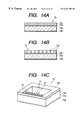
- FIGS. 14A, 14 B and 14 C show process flow diagrams of an example of a manufacturing method for a roof of a liquid discharging head of the present invention
- FIGS. 15A, 15 B, 15 C and 15 D show examples of a manufacturing method for a liquid discharging head of the present invention and particularly process flow diagrams showing processes after joining an element substrate with a roof;
- FIGS. 16A, 16 B, 16 C, 16 D and 16 E show process flow diagrams of another example of a manufacturing method for a liquid discharging head of the present invention
- FIGS. 17A, 17 B and 17 C show process flow diagrams of still another example of a manufacturing method for a liquid discharging head of the present invention
- FIGS. 18A and 18B show process flow diagrams of still another example of a manufacturing method for an element substrate of a liquid discharging head of the present invention
- FIGS. 19A, 19 B and 19 C show process flow diagrams of still another example of a manufacturing method for a roof of a liquid discharging head of the present invention
- FIGS. 20A, 20 B, 20 C, 20 D and 20 E show still other examples of a manufacturing method for a liquid discharging head of the present invention, and more particularly process flow diagrams for processes after joining an element substrate with a roof;
- FIGS. 21A, 21 B and 21 C show schematic top views of other shapes of a movable member
- FIG. 22 is a graph showing relationship between area of heat generating member and ink discharge amount
- FIGS. 23A and 23B show schematic side sectional views of a liquid discharging head of the present invention
- FIG. 24 is a graph showing an example of a driving pulse
- FIG. 25 is a schematic exploded perspective view of a liquid discharging head
- FIG. 26 is a schematic perspective view showing the major part of a liquid discharging apparatus.
- FIG. 27 is a block diagram of a liquid discharging apparatus.
- FIGS. 1A to 1 E are sectional schematic views of a liquid discharging head cut in the direction of the liquid flow
- FIG. 2 is a sectional cut perspective view of the liquid discharging head.
- the liquid discharging head illustrated in FIGS. 1A to 1 E are provided with a heat generating member 2 (in this example, a rectangular heat generating resistor of 40 ⁇ m ⁇ 105 ⁇ m) on an element substrate 1 for generating thermal energy which is an energy generating element to generate energy to be used for discharging liquid, and on the element substrate a liquid flow path 10 is disposed corresponding to the heat generating member 2 .
- the liquid flow path 10 is communicated with a discharging port 18 as well as a common liquid chamber 13 which is for feeding liquid to a plurality of liquid flow path 10 , and receives liquid from the common liquid chamber 13 in quantity equivalent to the quantity of liquid discharged from the discharging port.
- a plate-shaped movable member 31 On the element substrate of the liquid flow path 10 , opposingly faced with the heat generating member 2 , a plate-shaped movable member 31 , having a plane section, and composed of material having elasticity such as metal, is provided like a cantilever.
- One end of the movable member is secured to a base (support member) 34 or the like formed with photosensitive resin or the like subjected to patterning on a wall of the liquid flow path 10 or the element substrate.
- the base holds the movable member and constitutes a fulcrum (fulcrum section) 33 .
- the movable member 31 has the fulcrum (fulcrum section; fixed end) 33 on the upstream of a large flow, flowing to the side of a discharging port 18 from the common liquid chamber 13 via the movable member 31 , and is arranged apart from the heat generating member with distance of 15 ⁇ m in a state likely to cover the heat generating member 2 at a position facing to the heat generating member 2 for having a free end (free end section) 32 on the downstream relative to the fulcrum 33 .
- the region between the heat generating member and the movable member becomes a bubble generating region.
- the kind and shape of a heat generating member and a movable member are not restricted thereto, and a heat generating member and a movable member in such a shape and in an arrangement that may control bubble growth and pressure propagation may satisfactorily work to be described later.
- the liquid flow path 10 described above will further be described, divided by the movable member 31 into two regions comprising a first liquid path 10 a covering a section directly communicated with the discharging port 18 and a second liquid flow path 10 b having a bubble generating region 11 .
- One of the basic discharging principles to be applied to the present invention will be described here.
- One of the most important principles in this invention is that a movable member disposed opposingly to the bubble displaces from a first position or stationary state to a second position or a displaced position based on the pressure of the bubble or the bubble per se, and the displacing movable member 31 leads the pressure originated by the generation of the bubble or the bubble per se toward the downstream where the discharging port 18 is disposed.
- FIG. 3 schematically showing conventional liquid flow path without a movable member
- FIG. 4 illustrating the present invention.
- V A the direction of the pressure propagation toward the discharging port
- V B the direction of the pressure propagation toward the upstream
- the conventional heads as illustrated in FIG. 3 has no mechanism to regulate the propagation direction of the pressure by generated bubble 40 .
- the pressure propagation directions of the bubble 40 are perpendicular to the surface of the bubble as indicated by V 1 to V 8 , and is directed to various directions.
- directions having components of the pressure propagation direction in V A direction which particularly gives the greatest influence on the liquid discharging, are the directions having direction components of V 1 to V 4 or a portion nearer to the discharging port than the half way position of the bubble, and the portion is important in directly contributing to liquid discharging efficiency, liquid discharging force, discharging speed, and the like.
- V 1 being located nearest to the V A direction works efficiently, while V 4 to the contrary has comparatively small direction component toward V A .
- the movable member 31 leads the pressure propagation directions V 1 to V 4 of the bubble, which have been variously directed as in FIG. 3, toward the downstream (toward the discharging port), and convert the component of the pressure propagation direction into the pressure propagation direction of V A , thus the pressure from the bubble 40 directly contributes to efficient discharging.
- growth direction per se of the bubble is led toward the downstream similarly with the pressure propagation directions V 1 to V 4 , and the bubble grows larger in the downstream than in the upstream.
- a heat generating member 2 is in a state prior to application of energy such as electric energy or the like, namely the heat generating member is in a state prior to generating heat.
- the movable member 31 is, relative to a bubble generated by heat which is generated by the heat generating member, provided at a position at least facing to the downstream of the bubble.
- the movable member 31 is provided in the liquid flow path structure at least to a position downstream of the area center 3 of the heat generating member (downstream of a line which passes through the area center 3 of the heat generating member and orthogonally crosses lengthwise direction of the flow path).
- FIG. 1B shows a state where electric energy or the like is applied to the heat generating member 2 , heat is generated by the heat generating member 2 , and the heat thus generated heats a part of liquid filled the bubble generating region 11 , and a bubble is generated in association with film boiling.
- the removable member 31 displaces from a first position to a second position in such a way to lead the pressure propagation direction of the bubble 40 toward the discharging port by means of pressure based on the generation of the bubble 40 .
- a free end 32 of the movable member 31 is arranged on the downstream (the side of the discharging port), a fulcrum 33 is arranged so as to be positioned on the upstream (on the side of the common liquid chamber), and at least a part of the movable member is faced to the downstream section of the heat generating member or the downstream section of the bubble.
- FIG. 1C shows a state where the bubble 40 has further grown, but the movable member 31 is further displaced corresponding to the pressure associated with the generation of the bubble 40 .
- the movable member causes little hindrance to the transfer, and the pressure propagation direction and the bubble growth direction can be efficiently controlled depending on the magnitude of the propagating pressure.
- the upstream side of the movable member is displaced to a predetermined position with limited displacement resistance an upper wall lacking region 61 to promptly achieve the above described advantage, and thereafter, travel of the liquid to the upstream is prevented by collaboration between an upper wall 60 and a side wall 62 of the liquid flow path 10 to improve efficiency at the time of refilling.
- FIG. 1D shows a state where the bubble 40 , after the above described film boiling, shrinks to disappear with reducing pressure in the bubble.
- liquid flows in to the upstream namely like flows V D1 , VD D2 , VD D3 from the side of the common liquid chamber 13 , or a flow V C from the side of the discharging port.
- FIG. 1E shows a state where the movable member 31 comes down from the initial position (first position) after disappearance of the bubble 40 .
- the movable member 31 which has been displaced to a second position returns to the initial position (first position) in FIG. 1A by negative pressure due to shrinkage of the bubble and stability due to elasticity of the movable member per se.
- the movable member 31 is provided in the present structure, and as the result, when the volume W of a bubble is divided into an upper side W 1 of the first position and a side of W 2 of the bubble generating region, retreat of the meniscus substantially ceases at time point when the removable member returns to the initial position at the time of bubble disappearance, and the liquid feeding in the volume of W 2 left thereafter is performed by the liquid feeding mainly from the flow V D3 of a second liquid flow path 10 b .
- the meniscus retreat volume which has conventionally been a quantity equivalent to more or less half of the volume of the bubble W, can be reduced to approximately one half of W 1 , much reduced from the conventional quantity.
- liquid feeding in the volume of W 2 can be forcibly performed mainly from the upstream V D3 of the bubble generating region 11 , along a face of the side of the heat generating member of the movable member 31 taking advantage of the pressure at the time of bubble disappearance, faster refilling can be realized.
- liquid feeding V D1 from the upper wall lacking region 61 achieves extremely significant advantage, as described above.
- the region as the upper wall 60 and the side wall 62 are lacking, flow resistance is very small and high feeding performance can be obtained. More specifically, the structure yields better efficiency with high density nozzle arrangement which has narrow side wall width.
- the region has no side wall partitioning a plurality of liquid flow paths and defines a common communication space with which the liquid flow paths are commonly communicated.
- the movable member inhibits circulation of liquid at the side of the discharging port of the region of the liquid flow path 10 on the side of the discharging port side and the bubble generating region 11 , and meniscus vibration can be dramatically reduced.
- the above described structure to be applied to the present invention has feature of forcible refilling to a liquid flow path and a bubble generating region from region lacking upper wall, and high speed refilling by meniscus retreat or vibration inhibition, and the feature can be used in realizing stabilized discharging and high speed repetitive discharging, and when used in a field of recording, improvement in image quality and high speed recording.
- a nozzle in the present invention indicates a liquid flow path 10 from the orifice to the upstream of the side wall 62 , and the upper wall lacking region 61 having the side wall 62 is not included therein.
- the above described structure which is applied to the present invention is further provided with effective function as follows.
- the function is to inhibit propagation (back wave) toward the upstream of the pressure due to generation of the bubbles.
- the bubbles generated on the heat generating member 2 generate pressure, but the pressure due to the bubbles on the side of the common liquid chamber 13 (the upstream side) has mostly caused a force (back wave) to push back liquid toward the upstream.
- the back wave causes pressure on the upstream, liquid traveling volume due to the pressure, and inertia associated with the liquid traveling, all of which causes deterioration of refilling of liquid into a liquid flow path, which also hinders high speed driving of the apparatus.
- the movable member 31 inhibits such actions toward the upstream, which further improves feeding characteristic in refilling.
- a second liquid flow path 10 b comprises a flow path having an inner wall substantially connected evenly with the heat generating member 2 in the upstream of the heat generating member 2 (surface of the heat generating member is not largely sunken).
- liquid feeding to the bubble generating region 11 and the surface of the heat generating member 2 is performed along a face on side near to the bubble generating region 11 of the movable member 31 like V D3 .
- liquid is inhibited from being stayed on the surface of the heat generating member 2 , gas dissolved in the liquid is easily precipitated, bubbles left being not disappeared or so-called residual bubbles are easily removed, and heat storage in liquid can be restricted within a limit.
- a liquid discharging head comprising a liquid flow path having substantially flat inner wall, but this does not constitute any limitation to the present invention and other types of liquid flow path which is smoothly connected with the surface of the heat generating member and has smooth inner wall can work in the same way, and a liquid flow path in any shape that inhibits staying of the liquid over the heat generating member and large disturbance in the liquid feeding may suit to the object of the present invention.
- the free end is positioned, for example, as indicated in FIG. 5, relatively downstream to the fulcrum.
- function and advantage in leading the pressure propagation direction and the growth direction of the bubble at the time of above described generation of bubble toward the discharging port and the like can be efficiently realized.
- the positional relationship not only achieves function and advantage relative to the discharging, but also is capable of reducing flow resistance relative to the liquid flowing in the liquid flow path 10 , when liquid is being fed, to achieve advantage that refilling can be performed in high speed. This is because, as illustrated in FIG.
- the free end 32 and the fulcrum 33 are arranged in such a way that the free end and the fulcrum are not resisting to flows S 1 , S 2 , and S 3 which flow in the liquid flow path 10 (including a first liquid path 10 a , and a second liquid flow path lob), when meniscus M retreated by discharging is returned to the discharging port 18 by virtue of capillarity, and when liquid is fed to the disappeared bubbles.
- the free end 32 of the movable member 31 extends relative to the heat generating member 2 in such a way that the free end opposes to the position of the downstream relative to the area center 3 (a line passing through the area center (middle) of the heat generating member and orthogonally crossing the lengthwise direction of the liquid flow path) which divides the heat generating member 2 into an upstream region and a downstream region.
- FIGS. 1A to 1 E A first embodiment is described with reference to FIGS. 1A to 1 E.
- major principle on discharging liquid is also the same as the previous description.
- a side wall 62 is formed to the further upstream of the trailing end of the heat generating member 2 . Further, the upstream of the side wall 62 extends to a common liquid chamber 13 , and a wall lacking region 61 is formed thereabove.
- the movable member 31 and the wall 62 block or inhibit the flow of liquid to a nozzle disposed in the upstream and in the neighborhood, and inhibits traveling of the liquid toward the upstream.
- retreat volume of meniscus in a bubble disappearance process of the bubble 40 is reduced.
- the movable member 31 ceases to displace on the way when the movable member hits an upper wall 60 of the nozzle or a structure (protrusion or the like) in the nozzle, or because of rigidity of the movable member per se, and traveling of the liquid toward the upstream in the bubble growth process and toward the neighboring nozzle can be effectively inhibited.
- a nozzle in the present invention indicates a liquid flow path 10 from the orifice to the upstream of the side wall 62 , and the upper wall lacking region 61 having the side wall 62 is not included therein.
- FIGS. 6A to 6 E A second embodiment will be described referring to FIGS. 6A to 6 E.
- a movable member 31 is retracted to the vicinity of the center of a heat generating member 2 .
- the upstream of the side wall 62 is extended to the inside of a common liquid chamber 13 , and the upper wall lacking region 61 is formed thereabove.
- the movable member 31 ceases to displace on the way, when the movable member hits the upper wall 60 of the nozzle or the structure (protrusion or the like) in the nozzle, or by rigidity of the movable member per se, and the liquid travel in the bubble growth process to the upstream or toward the neighboring nozzle can be effectively inhibited.
- a third embodiment will be described with reference to FIGS. 7A to 7 E.
- the present embodiment is, in the same way as the first embodiment, as illustrated in FIG. 7A, a side wall 62 is raised the height thereof on the side of the upstream to the height to which the movable member 31 displaces, the end thereof is extended to the common liquid chamber 13 , and the wall lacking region 61 is formed thereabove. Similarly with the second embodiment, the free end 32 of the movable member 31 is receded to the vicinity of the center of the heat generating member 2 .
- FIGS. 8A to 8 E A fourth embodiment will be described referring to FIGS. 8A to 8 E.
- the side wall 62 is raised the height thereof on the side of the upstream to the height to which the movable member 31 displaces, but the upper part of the trailing end of the side wall 62 is obliquely cut to improve the more both the blocking properties against the upstream and the neighborhood and the refilling properties. Further, the upper wall 60 is raised in the downstream the higher as approaches to the discharging port 18 .
- the discharging efficiency can be improved more than the third embodiment.
- liquid (V D1 ) being fed from the bubble generating region 11 without excessive influence from the side wall 62 and the movable member 31 , the refilling frequency is improved more than the third embodiment.
- the fulcrum 33 of the movable member 31 exists nearby the heat generating member in the downstream of the side wall 62 , and liquid traveling volume toward the upstream at the time when the movable member 31 displaces is small, resultantly the meniscus retreat can be further inhibited. Further, such reduction of liquid traveling toward the upstream represents lesser reaction of liquid travelling toward the discharging port at the time of refilling, and the advantage further improves the refilling characteristics. Still more, influence to the neighboring nozzle is limited and the discharge instability element by the inter-nozzle crosstalk can be reduced.
- Materials of the composing members of the liquid discharging head in the above described embodiments 1 to 4 are selected depending on use situation of the materials, but improvement in reliability of the characteristic feature of the movable member, and the structure of flow path and liquid chamber, in the high density arrangement where thermal expansion conditions are made to be consistent is important. Then, a liquid discharging head having composing members corresponding to the object will be described.
- FIG. 9 is a sectional view along the liquid flow path direction of a liquid discharging head for describing basic structure of the liquid discharging head in a fifth embodiment of the present invention.
- the liquid discharging head comprises an element substrate 1 having a plurality (only one is shown in FIG. 9) of heat generating member 2 arranged in parallel for giving thermal energy to liquid for generating bubbles, a roof 50 seamed onto the element substrate 1 , and an orifice plate 63 seamed onto the front end faces of the element substrate 1 and the roof 50 .
- the element substrate 1 is a substrate of silicon or the like on which silicon dioxide film or silicon nitride film is applied for insulation and heat storage, and electric resistor layer and wiring are provided thereon by being subjected to patterning for composing the heat generating member 2 . Voltage is applied to the electric resistor layer from the wiring, and the heat generating member 2 is heated when current is applied to the electric resistor layer.
- the roof 50 is for composing a plurality of liquid flow path 10 corresponding to each heat generating member 2 , a common liquid chamber 13 for feeding liquid to each liquid flow path 10 , and a side wall 62 extending between the roof and each heat generating member 2 is provided as an integrated body.
- the roof 50 is composed of a material of silicon group, and can be formed by etching the portion of the liquid flow path 10 , after forming the pattern of the liquid flow path 10 and the common liquid chamber 13 by etching, and piling up materials such as silicon nitride, silicon dioxide and the like to be used for forming the side wall 62 on the silicon substrate by means of known film making method such as CVD or the like.
- the orifice plate 63 has a plurality of discharging ports 18 , formed thereon, communicated with the common liquid chamber 13 via respective liquid flow path 10 corresponding to each liquid flow path 10 .
- the orifice plate 63 is also made of a material of silicon group, and formed by, for example, cutting the silicon substrate by which the discharging port 18 has been formed to the thickness of 10 to 150 ⁇ m.
- the orifice plate 63 is not an essential structure for the present invention, and instead of providing the orifice plate 63 , and a roof with a discharging port can be formed in such a way that, when forming the liquid flow path 10 on the roof 50 , a wall of the thickness equivalent to the thickness of the orifice plate 63 is left on the front edge surface of the roof 50 , and the discharging port 18 is formed thereon.
- the liquid discharging head has a cantilever-shaped movable member 31 provided thereon, and the movable member is arranged to face to the heat generating member 2 in such a way that a first liquid flow path 10 a communicating the liquid flow path 10 with the discharging port 18 is separated from a second liquid flow path 10 b having the heat generating member 2 .
- the movable member 31 is a thin film formed with a material of silicon group such as silicon nitride, silicon dioxide, or the like.
- the movable member 31 has a fulcrum 10 a on the upstream of a large liquid flow flown from the common liquid chamber 13 toward the discharging port 18 via the movable member 31 by the discharging operation of the liquid, and is dispose of at a position facing to the heat generating member 2 , apart from the heat generating member 2 with a predetermined distance, and in a state to cover the heat generating member 2 so that a face end 32 may be held in the downstream relative to the fulcrum 10 .
- the region between the heat generating member 2 and the movable member 31 is the bubble generating region 11 .
- the liquid discharging head of the present embodiment uses silicon nitride (SiN) as a material for each composing parts thereof, ink resisting characteristic can be improved, and a problem of mechanical characteristic associated with the difference in line expansion ratio can be solved.
- SiN silicon nitride
- liquid discharging head When a liquid discharging head is manufactured by making a movable member, a nozzle wall, and an orifice plate as separate bodies, and assembling the parts on an element substrate, high density arrangement has been extremely difficult in view of the difficulty in assembling and high precision involved therein.
- problems of mechanical characteristic difference in linear expansion coefficient between an element substrate and a nozzle roof, and the like
- problems in assembling problems in assembling (adhesion of the movable member, fixing of the nozzle roof, specifically difficulty in fixing when the roof has the movable member thereon) are solved in a breath by incorporating the above mentioned each composing element into a film making process, and high density arrangement of the heating members on the element substrate is achieved to enable realization of high density discharging nozzle.
- FIGS. 10 A 1 , 10 A 2 to 10 F 1 , 10 F 2 and 11 G 1 , 11 G 2 to 11 I 1 , 11 I 2 are process flow diagrams of an example of manufacturing method for the liquid discharging head according to the present embodiment.
- FIGS. 10 A 1 , 10 B 1 , 10 C 1 , 10 D 1 , 10 E 1 , 10 F 1 , 11 G 1 , 11 H 1 and 11 I 1 are front sectional views
- FIGS. 10 A 2 , 10 B 2 , 10 C 2 , 10 D 2 , 10 E 2 , 10 F 2 , 11 G 2 , 11 H 2 and 11 I 2 are side sectional views.
- PSG Phospho-Silicate Glass
- Film thickness of the PSG film 201 corresponds finally to the gap between the moving section of the movable member and the heat generating member, and is controlled to take a value at which the advantage of the movable member is most remarkable, between 1 to 20 ⁇ m, in the balance of the flow path as a whole.
- the PSG film 201 is coated by a spin coater or the like with resist for patterning, then exposed and developed.
- resist of the portion corresponding to the fixed section of the movable member is removed.
- the PSG film 201 on the portion lacking resist is removed by wet etching with buffered hydrofluoric acid. Residual resist is then removed by plasma ashing by oxygen plasma, or by soaking into resist coating agent.
- SiN film 202 is formed by sputtering in the thickness of 1 to 10 ⁇ m. Composition of SiN film 202 is said be best with Si 3 N 4 , but as effect on the moving members may be satisfactory when the position is in the range of Si: 1 and N: 1 to 1.5.
- the SiN film 202 has been generally used in semiconductor process, and has alkali-resisting and acid-resisting properties and chemical stability, and is also ink-resisting. In other words, manufacturing method for the film 202 is not restricted, in achieving the structure and the composition that realize the optimum characteristic as the material for the movable members.
- forming method of SiN film 202 is not restricted to above mentioned sputtering, and the film can be manufactured also by atmospheric CVD, LPCVD, bias ECRCVD, microwave CVD, or coating method.
- percentage composition of the film is changed by stages in making multi-layer structure in order to improve the characteristic, such as physical characteristic like stress, rigidity, Young's modulus, and the like, and chemical characteristic like alkali-resisting, acid-resisting, and the like, to meet the use application.
- impurities may be added in stages to make a multi-layer structure, or impurities may be added to a single layer.
- damage protecting film 203 is formed. Namely, when the movable member and the flow path wall are of substantially same material, the movable member may also be etched when forming the flow path wall by etching, and a protective film is required for the projection. In this embodiment, Al film being the protective film 203 is formed in the thickness of 2 ⁇ m by sputtering.
- SiN film 207 as material for a flow path wall and an orifice plate is formed into a thickness of 20 to 40 ⁇ m by CVD method, or by microwave CVD method when high speed film forming is particularly required.
- the film 207 becomes the flow path wall or the orifice portion after the patterning.
- the SiN film 207 is not influenced by usual film characteristic required in the ordinary semiconductor process such as, for example, pin hole density and film denseness. Namely, the film is usable as long as ink-resisting characteristic and mechanical strength are enough satisfactory as a flow path wall relative to ink, and slight increase in pin hole density by high speed film forming or the like is not mattered instead.
- the material for a flow path wall is not restricted to the SiN film as is described previously, and SiN film including impurities and SiN film of different composition may be usable as long as mechanical characteristic and ink resisting characteristic are held, and diamond film, amorphous carbon hydride film (diamond carbon film), and inorganic film made of alumina group, zirconia group, or the like may be used.
- resist is coated by spin coater or the like for patterning.
- the film is then subjected to dry etching using CF 4 gas or the like, or reactive ion etching.
- ICP inductive coupling plasma
- etching is best suited for etching the thick film 207 from the stand point of high speed etching characteristic.
- residual resist is removed by means of plasma ashing by oxygen plasma, or by soaking into resist removing agent. The flow path wall 204 is thus formed.
- the damage protective film 203 on the movable member is removed by wet etching or dry etching.
- the method does not matter as long as the damage protective film 203 is removed.
- the film is formed with high ink-resisting material like Ta, the film is not required to be removed, so long as the damage protective film 203 does not wrongly influence the characteristic of the movable member.
- a flow path wall and the movable member are formed on a substrate at a time, but an orifice member can also be formed at the same time.
- the wall of the orifice member 206 is formed at the same time in a thickness of 2 to 30 ⁇ m as illustrated in FIGS. 12 G 1 , 12 G 2 to 12 J 1 , 12 J 2 . Then, a hole is drilled on the wall by application process by way of excimer laser.
- Fixing of the movable member and the roof can be performed with precision (on account of photolithography).
- High density discharging nozzle can be manufactured. Conventionally, fixing of the movable member has been difficult, for example, with 1200 dpi.
- Adhesion of the movable member is unnecessary, and staining by adhesive and bonding can be avoided.
- driver Tr LDMOS
- FIGS. 13A, 13 B, 14 A to 14 C, 15 A to 15 D are diagrams illustrating manufacturing methods for a liquid discharging head according to the present invention.
- PSG film 71 b of a thickness of about 5 ⁇ m is formed (refer to FIG. 13A) using plasma CVD method, and the substrate is then subjected to patterning using known method such as photolithography or the like. Then, using ⁇ W-CVD (microwave Chemical Vapor Deposition) method, a movable member 76 composed of SiN film of about 5 ⁇ m thickness is formed. At this moment, the PSG film 71 b and the movable member 76 are in a state that portions in the flow path 77 have been subjected to comb-shaped patterning (refer to FIG. 13 B).
- ⁇ W-CVD microwave Chemical Vapor Deposition
- a silicon substrate to be a roof 73 is formed by patterning the portion to be a common liquid chamber using known method such as photolithography or the like.
- a layer 73 of SiN or the like to be flow path side wall 79 is formed in a thickness of about 20 ⁇ m by ⁇ W-CVD method (refer to FIG. 14 A).
- the orifice portion and the flow path portion are subjected to patterning, and etched into trench structure using etching device by means of inductive coupling plasma.
- FIG. 14C is a perspective view of a completed roof 73 .
- FIG. 15A is a side sectional view illustrating a state where the element substrate 71 and the roof 73 are seamed together
- FIG. 15B is a front sectional view thereof. As can be seen from FIG.
- the liquid flow path 77 , the common liquid chamber 78 , and the feeding port 81 are formed on the roof 73 , at the time when both the substrate and the roof are seamed together, but the orifice 75 is still to be formed.
- the orifice 75 is formed by ion beam processing by means of a mask 100 in the vacuum atmosphere (refer to FIG. 15 D).
- the PSG film 71 a is removed by wet etching method. In this way, a liquid discharging head is manufactured.
- ink is discharged only from a discharging head which is communicated with a liquid flow path with a driven heat generating member provided thereon.
- the element substrate 71 , the roof 73 , and the movable member 76 are all formed of material containing silicon, and as the thermal expansion coefficients of the members are substantially same, even if the temperature thereof is increased associated with high speed printing, relative to positional precision and adhesive properties of each member are maintained, enabling stabilized ink discharging in wide temperature range, and high quality printing is possible in high efficiency.
- the seaming of the substrate is performed without using adhesives, variation of the flow path resistance and deterioration of discharging performance due to sagging of the adhesives into the liquid flow path can be prevented.
- the element substrate 71 and the roof 73 are formed with material containing silicon, and more particularly with inorganic compound such as silicon nitride or the like, the substrate and the roof can be formed in high density with easy processing.
- FIGS. 16A to 16 E and 17 A to 17 C illustrate other examples of manufacturing method for the liquid discharging head. Now, only points which are different from the previous examples will be described.
- FIGS. 16A to 16 D are front sectional views
- FIG. 16 E and FIGS. 17A to 17 C are side sectional views.
- PSG film 71 b of about 5 ⁇ m thick on the substrate 71 a (refer to FIG. 16 A)
- the substrate is subjected to patterning using known method such as photolithography or the like.
- a movable member 76 comprising SiN film of about 5 ⁇ m thick is formed using ⁇ W-CVD method.
- the PSG film 71 b and the movable member 76 are in a state where only the portion of the liquid flow path 77 has been subjected to comb-shaped patterning (refer to FIG. 16 B).
- An etching stop layer (not shown) composing of a metal film of 1000 ⁇ thick is formed thereon by sputtering method or evaporation method.
- the orifice portion and the liquid flow path portion are subjected to patterning, and the trench structure is etched using etching device by means of inductive coupling plasma, using the metal film as the etching stop layer. In this way, the element substrate 82 is completed (refer to FIGS. 16D, 16 E).
- a common liquid chamber 81 is formed by silicon wafer break-through etching by means of TMAH.
- the element substrate 82 and the roof 83 are seamed together by the room temperature seaming similarly with a previous example (refer to FIG. 16 A).
- the orifice 75 is formed by excimer laser processing (refer to FIG. 16B) using the mask 100 .
- a liquid discharging head is completed by removing the PSG film 71 b by wet etching method (refer to FIG. 16 C).
- a liquid flow path 77 b and a common liquid chamber 81 are provided on the side of the element substrate 82 , not on the roof 83 .
- the liquid discharging head in the form as illustrated in FIG. 15D, or FIG. 17C is extremely advantageous in the following points.
- the liquid discharging head is provided with a cantilever-shaped movable member 76 , arranged facing to the heat generating member 72 , and directly secured to the element substrate 71 .
- the movable member 76 has a curvature, and the movable section of the movable member 76 is disposed to have a predetermined slit relative to the substrate by the curvature.
- the movable member By making the movable member in such shape, the movable member can be firmly secured, and as a pedestal is no more required in forming the slit, the space conventionally occupied by the pedestal can be used as a part of the liquid chamber, and volume of the liquid chamber is easily secured. Further, when the movable member is made in the above mentioned structure, the movable member is required to have more strength than the conventional structure, and the movable member 76 in the present invention is made of thin film formed with material of silicon group or the like such as silicon nitride, silicon dioxide, or the like. As these materials are superior to nickel in strength which has conventionally been used as material for the movable member, and are superior in adhesive properties with insulating protective layer provide on the surface of the substrate, the materials can demonstrate stabilized characteristic in the above-mentioned structure.
- FIGS. 18A, 18 B, 19 A to 19 C, 20 A to 20 E further illustrate other examples of manufacturing method for a liquid discharging head.
- the present examples have structure similar to the previous examples, but thin film 84 , which is integrated seaming section 84 a and a plurality of movable member 84 b, is used.
- the thin film may be formed of material containing silicon such as SiN, SiC, or the like, and metals of which thermal expansion coefficient is brought nearer to that of Si such as Ni, W, Ta, Pb, Mo, Cr, Mn, Fe, Co, Cu, or the like may be used as the material.
- a film layer 3 c of SiN or the like to be a flow path side wall 9 is formed in a thickness of about 20 ⁇ m by ⁇ W-CVD method (refer to FIG. 19 A), orifice portion and liquid flow path portion are subjected to patterning using known method of photolithography or the like, and a trench structure is subjected to etching using a etching device by means of inductive coupling plasma. Thereafter, using TMAH, the silicon substrate is subjected to silicon wafer break-through etching to complete a roof 73 , which is integrated with the orifice place into an integrated body (refer to FIG. 19 B).
- FIG. 19C is a perspective view showing the completed roof 73 .
- FIG. 20D illustrates a side sectional view of the element substrate 85 and the roof 73 in a state seamed together.
- ion beam processing is performed using the mask 100 in vacuum atmosphere to form the orifice 75 . In this way, by the power of ion beam, the orifice 75 is formed (refer to FIG. 20 E).
- the PSG film 85 b is removed by wet etching method.
- a liquid discharging head of the present embodiment is completed.
- FIGS. 21A to 21 C illustrates other shapes of the movable member 31 and numberal 35 is a slit provided in a separation wall, by which the movable member 31 is formed.
- FIG. 21A is a rectangular shape
- FIG. 20B is a shape in which fulcrum side is made narrow to enable easier operation of the movable member
- FIG. 20C is a shape in which fulcrum side is made wide to improve durability of the movable member.
- the plate-shaped movable member 31 and the separation wall 30 having the movable member thereon are composed of nickel of 5 ⁇ m thick, but the material is not restricted thereto and any material which has solvent-resisting properties, and elasticity for advantageous operation of the removable member, and which allows forming of fine slit thereon, may be suited as material to compose the movable member and the separation wall.
- Desirable materials for the movable member 31 are metals of high durability such as silver, nickel, gold, iron, titanium, aluminum, platinum, tantalum, stainless steel, phosphor bronze, or the like, or alloys thereof, resins having nitrile group such as acrylonitrile, butadiene, styrene, or the like, resins having amide group such as polyamide or the like, resins having carboxyl group such as polycarbonate or the like, resins having aldehyde group such as polyacetals or the like, resins having sulfo group such as polysulfon or the like, other resins such as liquid crystal polymer or the like or compounds thereof, metals having high ink-resistance such as gold, tungsten, tantalum, nickel, stainless steel, titanium, or the like or compounds thereof, and with respect to the ink-resistance, materials coated thereon with metals above mentioned, resins having amide group such as polyamide or the like, resins having aldehyde group
- Desirable materials for the separation wall are resins which have good heat resistance, good solvent resistance, and good properties for molding, represented by latest engineering plastics such as polyethylene, polypropylene, polyamide, polyethylene terephthalate, melamine resins, phenol resins, epoxy resins, polybutadiene, polyurethane, polyether etherketone, polyethersulfon, polyallylate, polyimide, polysulfon, liquid crystal polymer (LCP), or the like, or compounds thereof, or silicon dioxide, silicon nitride, metals such as nickel, gold, stainless steel, or the like, or alloys or compounds thereof, or any material coated the surface thereof with titanium or gold.
- latest engineering plastics such as polyethylene, polypropylene, polyamide, polyethylene terephthalate, melamine resins, phenol resins, epoxy resins, polybutadiene, polyurethane, polyether etherketone, polyethersulfon, polyallylate, polyimide, polysulfon, liquid crystal polymer
- the thickness of the separation wall 30 may be determined in consideration of the properties and the shapes of the material from view points that the strength as the separation wall 30 can be achieved and the movable member 31 is assured of good operation, but preferably the thickness is around 0.5 ⁇ m to 10 ⁇ m.
- the thickness of the slit 35 for forming the movable member 31 is made 2 ⁇ m in the present embodiment, but the bubbling liquid and the discharging liquid are different liquid, if both liquid is to be prevented from being mixed, the slit width may be a gap in a size such that meniscus can be formed between both liquid to inhibit flow of respective liquid for preventing mixing up.
- the slit width may be a gap in a size such that meniscus can be formed between both liquid to inhibit flow of respective liquid for preventing mixing up.
- the movable member 31 For the movable member 31 according to the present invention, thickness in the order of ⁇ m (t ⁇ m) is in the consideration, and the movable member of the thickness of cm order is out of consideration.
- the movable member of the thickness in ⁇ m order when the slit is to be made in the order of ⁇ m (W ⁇ m), preferably dispersion in manufacturing is to be considered to a degree.
- the relationship between the slit width and the thickness may be regulated in a range to be described hereafter paying attention to the dispersion in manufacturing so that the liquid mixing between the bubbling liquid and the discharging liquid can be inhibited.
- the movable member when liquid function is separated to a bubbling liquid and a discharging liquid, the movable member works as a practical separator. When the movable member travels in association with the generation of bubbles, bubbling liquid is observed to mix into discharging liquid in minor quantity. Considering from a point that the density of the coloring material in the discharging liquid for forming an image is generally around from 3% to 5%, in the case of ink jet recording, even if the bubbling liquid is contained in the discharging liquid droplet within a range of 20% or less thereof, variation of the concentration of the discharging liquid droplet is limited. Accordingly, mixed liquid such as the mixture of the bubbling liquid and the discharging liquid containing the bubbling liquid in a ratio 20% or less of the mixture is included in the scope of the present invention.
- upper limit is mixture of 15% bubbling liquid, and with bubbling liquid of 5 cps or less
- the upper limit of the mixture ratio is, although depending on driving frequency, around 10%.
- the viscosity of discharging liquid is reduced to 20 cps or lower, the mixture may be the more reduced (for example 5% or less).
- ink jet recording method or in the conventional technique so-called bubble jet recording method, where energy from heat or the like to ink is first given to ink, the ink then suffers a state change associated with abrupt volume change (generation of bubbles) and is discharged from a discharging port by action force based on the state change, and the ink is adhered to a recording medium to form an image.
- the area of the heat generating member is proportional to the discharged quantity of ink, as illustrated in FIG. 22, where ineffective region S for bubble generating is also illustrated. From the appearance of the burnt deposit on the heat generating member, the ineffective region S for bubble generating is known to be existing in the periphery of the heat generating member. From such observation, the periphery within 4 ⁇ m wide of the heat generating member is considered to be not related with the bubble generation.
- arrangement of the movable member can be effectively made if the movable member is arranged such that the operation region of the movable member can cover the right above the effective region of bubble generation which is around 4 ⁇ m or more inside the periphery of the heat generating member.
- effective region of the bubble generation is restricted to be 4 ⁇ m or more inside the periphery of the heat generating member, the region is not restricted thereto depending on kind and generating method of the heat generating member.
- FIGS. 23A and 23B are longitudinal sectional views of a liquid discharging head according to the present invention, and FIG. 23A illustrates the head with protective film to be described later, and FIG. 23B illustrates the head without the protective film.
- a second liquid flow path 16 On the element substrate 1 , a second liquid flow path 16 , a separation wall 30 , a first liquid flow path 14 , and a grooved member 50 provided with a groove composing a first liquid flow path are arranged.
- a silicon dioxide film or a silicon nitride film 106 is formed on a base member 107 of silicon and the like for insulation and heat storage, and over the film, an electric resistor layer 105 (0.01 to 0.2 ⁇ m thick) of hafnium borate (HfB 2 ), tantalum nitride (TaN), tantalum aluminum (TaAl) or the like and a wiring electrode 104 (0.2 to 1.0 ⁇ m thick) of aluminum and the like are applied by patterning. Voltage is applied from the wiring electrodes 104 to the resistor layer 105 , and current is fed to the resistor layer to generate heat.
- HfB 2 hafnium borate
- TaN tantalum nitride
- TaAl tantalum aluminum
- a wiring electrode 104 0.2 to 1.0 ⁇ m thick
- a protective film 103 of silicon dioxide, silicon nitride, or the like is formed in the thickness of 0.1 to 2.0 ⁇ m, and over the protective film, a cavitation resisting film layer 102 (0.1 to 0.6 ⁇ m thick) of tantalum or the like is formed to protect the resistor layer 105 from a variety of liquids such as ink or the like.
- cavitation resisting layer 102 is formed with metal material such as tantalum or the like.
- resistor 105 may be a structure in which the protective layer 103 is not required, depending on the combination of liquid, liquid flow path structure, and resistor material, and an example thereof is illustrated in FIG. 23 B.
- the material for the resistor layer 105 which does not require the protective layer 103 iridium-tantalum-aluminum alloy or the like may be named.
- the heat generating member in each of the previously mentioned embodiment may be of the structure with only the resistor layer (heat generating section) between the electrode, or the structure including the protective layer for protecting the resistor layer.
- the present embodiment uses a heat generating member having a heat generating section composed of a resistor layer which generate heat in correspondence with electric signal, but the type of heat generating member is not restricted thereto, and any type of the heat generating member suits for the object of the present invention as long as the heat generating member can cause bubbling liquid to generate bubbles enough to discharge the discharging liquid.
- a heat generating member may have, as a heat generating section, a light-heat converter which may generate heat by receiving light of laser or the like, or a heat generating section which may generate heat by receiving high-frequency waves.
- a rectangular pulse as illustrated in FIG. 24 is applied to the resistor layer 105 via the wiring electrodes 104 , and the resistor layer 105 between the wiring electrodes abruptly generates heat.
- voltage 24 V, pulse amplitude 7 ⁇ sec, current 150 mA, and electrical signal 6 kHz are respectively applied to the heat generating member to drive the same, and by the operation previously described, ink being a liquid is discharged from the discharging port.
- condition for driving signal is not restricted to such described, and any driving signal which can cause the bubbling liquid to properly generate bubbles may be used.
- liquid can be discharged in stronger discharging force and higher discharging efficiency, and moreover in high speed, than the conventional liquid discharging head.
- the liquid in the case where the same liquid is used for the bubbling liquid and the discharging liquid, the liquid is not deteriorated by the heat applied from the heat generator, dumps on the heat generator are hardly to be generated by heating, reversible state change between vaporization and condensation is possible by heat, and a variety of liquid may be used as long as the liquid has no danger to deteriorate the liquid flow path, movable member, or separation wall.
- ink of the composition used for the conventional bubble jet apparatus may be used as a liquid to be used in recording.
- a discharging liquid As a discharging liquid, a variety of liquid may be used irrespective of bubbling properties and thermal characteristic. Further, liquid of inferior bubbling properties which has caused discharging difficulty with the conventional apparatus, liquid easy to change quality and deteriorate by heat, and even high viscosity liquid may be used. However, desirable quality is that, as the nature of the liquid, the liquid may not disturb discharging, bubble generation, operation of the movable member, or the like by reaction of the discharging liquid per se or with the bubbling liquid. As the discharging liquid for recording, high viscosity ink or the like may be used. As the other discharging liquid, liquid of pharmaceutical, perfume, or the like which is susceptible to heat may be used.
- ink of the following composition has been used for recording.
- discharging speed has been accelerated by improvement in discharging force, impinging precision of liquid droplet has been improved so that a very good quality recorded image has been obtained.
- Dyeing Ink (Viscosity 2 cP) (C-1. Food Black 2) dye 3 weight % Diethylene glycol 10 weight % Thiodiglycol 5 weight % Ethanol 5 weight % Water 77 weight %
- FIG. 25 is an exploded perspective view illustrating a whole structure of a liquid discharging head according to the present invention.
- a supporter 70 of aluminum or the like an element substrate 1 with the heat generating member 2 arranged thereon is provided.
- a wall of the second flow path 10 and a wall of the common liquid chamber 13 are provided, and thereover, a separation wall 30 having the movable member 31 is provided. Further, on the separation wall 30 , a plurality of grooves composing the first liquid flow path 10 a and the roof 50 where a wall of the common liquid chamber 13 is disposed are provided.
- FIG. 26 illustrates schematic structure of a liquid discharging apparatus having above described liquid jetting head mounted thereon.
- a carriage HC of the liquid discharging apparatus has a head cartridge where a liquid tank 90 for storing ink and a liquid discharging head 200 are removably mounted thereon, and reciprocally travels in the widthwise direction of a printing medium 150 of recording paper or the like conveyed by a printing medium conveying means.
- a driving signal is fed to the liquid discharging means on the carriage from a driving signal feeding means which is not shown in Figures, recording liquid is discharged to the recording medium from the liquid discharging head corresponding to the signal.
- a motor 111 being driving source for driving the printing medium conveying means and the carriage, gears 112 , 113 , for conducting power from the driving source to the carriage, carriage shaft 115 and the like are provided.
- a liquid discharging method performed by the recording apparatus, recorded materials in good quality image can be obtained by discharging liquid onto a variety of recording mediums.
- FIG. 27 is a block diagram of the whole apparatus for operating ink discharging recording with the liquid discharging method and the liquid discharging head according to the present invention applied thereto.
- the recording apparatus receives printing information from a host computer 300 as a control signal.
- the printing information is temporarily stored in an input interface 301 in the printing apparatus, simultaneously converted into data capable of being processed in the recording apparatus, and inputted into CPU 302 which also works as a head driving signal feeding means.
- the CPU 302 processes the data inputted into the CPU 302 using peripheral units such as RAM 304 and the like to convert into data (image data) to be printed.
- the CPU 302 produces driving data for driving the driving motor to travel, in synchronization with the image data, the recording paper and a recording head.
- the image data and the motor driving data are transferred to the head 200 and a driving motor 306 via a head driver 307 and a motor driver 305 respectively, and are respectively driven in controlled timing to form an image.
- a printing medium applicable to the recording apparatus as described above and to be given liquid such as ink or the like a variety of papers or OHP sheets, plastic which is used for a compact disc or a decoration plate, woven fabric, metal such as aluminum, copper, or the like, leather such as cattle skin, pork skin, artificial leather, or the like, wood such as tree, plywood laminate, or the like, bamboo, ceramic such as a tile or the like, three dimensional structure material such as sponge or the like may be intended.
- the recording apparatus described above also includes a printer apparatus for recording on a variety of papers, OHP sheets, or the like, a recording apparatus for plastics for recording on plastic such as a compact disc and the like, a recording apparatus for metals for recording on a metal plate, a recording apparatus for leather for recording on leather, a recording apparatus for wood for recording on wood, a recording apparatus for ceramic for recording on ceramics, a recording apparatus for recording on three dimensional netting structure member such as sponge and the like, a textile printing apparatus for recording on woven fabrics, and the like.
- discharging liquid to be used for such liquid discharging apparatuses liquid suited for respective recording mediums and recording conditions may be used.
Landscapes
- Engineering & Computer Science (AREA)
- Manufacturing & Machinery (AREA)
- Physics & Mathematics (AREA)
- Optics & Photonics (AREA)
- Particle Formation And Scattering Control In Inkjet Printers (AREA)
- Ink Jet (AREA)
Applications Claiming Priority (6)
| Application Number | Priority Date | Filing Date | Title |
|---|---|---|---|
| JP9-336055 | 1997-12-05 | ||
| JP9-336108 | 1997-12-05 | ||
| JP33605597 | 1997-12-05 | ||
| JP9-336109 | 1997-12-05 | ||
| JP33610997 | 1997-12-05 | ||
| JP33610897 | 1997-12-05 |
Publications (2)
| Publication Number | Publication Date |
|---|---|
| US20020015078A1 US20020015078A1 (en) | 2002-02-07 |
| US6491380B2 true US6491380B2 (en) | 2002-12-10 |
Family
ID=27340761
Family Applications (1)
| Application Number | Title | Priority Date | Filing Date |
|---|---|---|---|
| US09/204,264 Expired - Fee Related US6491380B2 (en) | 1997-12-05 | 1998-12-03 | Liquid discharging head with common ink chamber positioned over a movable member |
Country Status (3)
| Country | Link |
|---|---|
| US (1) | US6491380B2 (de) |
| EP (1) | EP0921002B1 (de) |
| DE (1) | DE69830700T2 (de) |
Cited By (8)
| Publication number | Priority date | Publication date | Assignee | Title |
|---|---|---|---|---|
| US20030197763A1 (en) * | 2002-04-23 | 2003-10-23 | Canon Kabushiki Kaisha | Liquid discharge head and method of manufacturing the same |
| US20040056928A1 (en) * | 2001-08-10 | 2004-03-25 | Canon Kabushiki Kaisha | Ink jet recording head and method for manufacturing the same |
| US6945635B2 (en) | 1999-09-03 | 2005-09-20 | Canon Kabushiki Kaisha | Liquid discharge method, liquid discharge head, liquid discharge apparatus, and method for manufacturing liquid discharge head |
| US20060114295A1 (en) * | 2004-12-01 | 2006-06-01 | Canon Kabushiki Kaisha | Liquid discharge head and method of manufacturing the same |
| US20060277755A1 (en) * | 2004-06-28 | 2006-12-14 | Canon Kabushiki Kaisha | Liquid discharge head manufacturing method, and liquid discharge head obtained using this method |
| US20070165067A1 (en) * | 2004-11-10 | 2007-07-19 | Canon Kabushiki Kaisha | Liquid discharge head |
| US8684501B2 (en) | 2010-04-29 | 2014-04-01 | Hewlett-Packard Development Company, L.P. | Fluid ejection device |
| US9446592B2 (en) | 2014-05-30 | 2016-09-20 | Canon Kabushiki Kaisha | Liquid ejection cartridge and liquid ejection apparatus |
Families Citing this family (6)
| Publication number | Priority date | Publication date | Assignee | Title |
|---|---|---|---|---|
| AUPQ130399A0 (en) * | 1999-06-30 | 1999-07-22 | Silverbrook Research Pty Ltd | A method and apparatus (IJ47V9) |
| EP1072419B1 (de) * | 1999-07-27 | 2004-09-29 | Canon Kabushiki Kaisha | Drucker und Druckverfahren |
| US6435661B1 (en) * | 1999-09-03 | 2002-08-20 | Canon Kabushiki Kaisha | Liquid discharge head, liquid discharge method and liquid discharge apparatus |
| EP1177902A1 (de) | 2000-07-31 | 2002-02-06 | Canon Kabushiki Kaisha | Flüssigkeitsausstosskopf,Verfahren zur Herstellung eines Flüssigkeitsausstosskopfes, Kassette mit darauf montiertem Flüssigkeitsausstosskopf und Flüssigkeitsausstossvorrichtung |
| US20030037302A1 (en) * | 2001-06-24 | 2003-02-20 | Aliaksei Dzienis | Systems and methods for automatically converting document file formats |
| JP6848264B2 (ja) * | 2016-08-25 | 2021-03-24 | 東洋製罐株式会社 | 加飾多層押出ブローボトルの製造方法。 |
Citations (21)
| Publication number | Priority date | Publication date | Assignee | Title |
|---|---|---|---|---|
| JPS5581172A (en) | 1978-12-14 | 1980-06-18 | Canon Inc | Liquid injection type recording method and device |
| US4450455A (en) | 1981-06-18 | 1984-05-22 | Canon Kabushiki Kaisha | Ink jet head |
| US4480259A (en) | 1982-07-30 | 1984-10-30 | Hewlett-Packard Company | Ink jet printer with bubble driven flexible membrane |
| US4558333A (en) | 1981-07-09 | 1985-12-10 | Canon Kabushiki Kaisha | Liquid jet recording head |
| JPS6119372A (ja) | 1984-07-07 | 1986-01-28 | Nec Corp | インクジエツトヘツド |
| EP0176596A1 (de) | 1982-11-26 | 1986-04-09 | Mitsubishi Denki Kabushiki Kaisha | Analog-eingangsschaltung |
| JPS6169467A (ja) | 1985-06-11 | 1986-04-10 | Seiko Epson Corp | 記録液滴吐出型記録装置 |
| US4611219A (en) | 1981-12-29 | 1986-09-09 | Canon Kabushiki Kaisha | Liquid-jetting head |
| US4646110A (en) | 1982-12-29 | 1987-02-24 | Canon Kabushiki Kaisha | Liquid injection recording apparatus |
| US4723129A (en) | 1977-10-03 | 1988-02-02 | Canon Kabushiki Kaisha | Bubble jet recording method and apparatus in which a heating element generates bubbles in a liquid flow path to project droplets |
| JPS63199972A (ja) | 1987-02-13 | 1988-08-18 | Canon Inc | 弁素子の製造方法 |
| JPS6490754A (en) | 1987-10-01 | 1989-04-07 | Canon Kk | Ink jet recording head |
| US4994825A (en) | 1988-06-30 | 1991-02-19 | Canon Kabushiki Kaisha | Ink jet recording head equipped with a discharging opening forming member including a protruding portion and a recessed portion |
| EP0436047A1 (de) | 1990-01-02 | 1991-07-10 | Siemens Aktiengesellschaft | Flüssigkeitsstrahlaufzeichnungskopf für Tintendruckeinrichtungen |
| US5208604A (en) | 1988-10-31 | 1993-05-04 | Canon Kabushiki Kaisha | Ink jet head and manufacturing method thereof, and ink jet apparatus with ink jet head |
| JPH05124189A (ja) | 1991-11-01 | 1993-05-21 | Matsushita Electric Ind Co Ltd | インク吐出装置 |
| US5278585A (en) * | 1992-05-28 | 1994-01-11 | Xerox Corporation | Ink jet printhead with ink flow directing valves |
| US5389957A (en) | 1989-09-18 | 1995-02-14 | Canon Kabushiki Kaisha | Ink jet head with contoured outlet surface |
| EP0745479A2 (de) | 1995-06-02 | 1996-12-04 | Canon Kabushiki Kaisha | Apparat und Verfahren zum Ausstossen von Flüssigkeit |
| US5657539A (en) | 1991-10-22 | 1997-08-19 | Canon Kabushiki Kaisha | Process for producing an ink jet recording head |
| US5943074A (en) | 1996-06-07 | 1999-08-24 | Canon Kabushiki Kaisha | Liquid discharge method and liquid discharge apparatus |
Family Cites Families (1)
| Publication number | Priority date | Publication date | Assignee | Title |
|---|---|---|---|---|
| CA1237020A (en) * | 1984-10-13 | 1988-05-24 | Herbert A. Waggener | Silicon nozzle structure and method of manufacture |
-
1998
- 1998-12-03 US US09/204,264 patent/US6491380B2/en not_active Expired - Fee Related
- 1998-12-04 EP EP98123174A patent/EP0921002B1/de not_active Expired - Lifetime
- 1998-12-04 DE DE69830700T patent/DE69830700T2/de not_active Expired - Lifetime
Patent Citations (22)
| Publication number | Priority date | Publication date | Assignee | Title |
|---|---|---|---|---|
| US4723129A (en) | 1977-10-03 | 1988-02-02 | Canon Kabushiki Kaisha | Bubble jet recording method and apparatus in which a heating element generates bubbles in a liquid flow path to project droplets |
| JPS5581172A (en) | 1978-12-14 | 1980-06-18 | Canon Inc | Liquid injection type recording method and device |
| US4450455A (en) | 1981-06-18 | 1984-05-22 | Canon Kabushiki Kaisha | Ink jet head |
| US4558333A (en) | 1981-07-09 | 1985-12-10 | Canon Kabushiki Kaisha | Liquid jet recording head |
| US4611219A (en) | 1981-12-29 | 1986-09-09 | Canon Kabushiki Kaisha | Liquid-jetting head |
| US4480259A (en) | 1982-07-30 | 1984-10-30 | Hewlett-Packard Company | Ink jet printer with bubble driven flexible membrane |
| EP0176596A1 (de) | 1982-11-26 | 1986-04-09 | Mitsubishi Denki Kabushiki Kaisha | Analog-eingangsschaltung |
| US4646110A (en) | 1982-12-29 | 1987-02-24 | Canon Kabushiki Kaisha | Liquid injection recording apparatus |
| JPS6119372A (ja) | 1984-07-07 | 1986-01-28 | Nec Corp | インクジエツトヘツド |
| JPS6169467A (ja) | 1985-06-11 | 1986-04-10 | Seiko Epson Corp | 記録液滴吐出型記録装置 |
| JPS63199972A (ja) | 1987-02-13 | 1988-08-18 | Canon Inc | 弁素子の製造方法 |
| JPS6490754A (en) | 1987-10-01 | 1989-04-07 | Canon Kk | Ink jet recording head |
| US4994825A (en) | 1988-06-30 | 1991-02-19 | Canon Kabushiki Kaisha | Ink jet recording head equipped with a discharging opening forming member including a protruding portion and a recessed portion |
| US5208604A (en) | 1988-10-31 | 1993-05-04 | Canon Kabushiki Kaisha | Ink jet head and manufacturing method thereof, and ink jet apparatus with ink jet head |
| US5389957A (en) | 1989-09-18 | 1995-02-14 | Canon Kabushiki Kaisha | Ink jet head with contoured outlet surface |
| EP0436047A1 (de) | 1990-01-02 | 1991-07-10 | Siemens Aktiengesellschaft | Flüssigkeitsstrahlaufzeichnungskopf für Tintendruckeinrichtungen |
| US5657539A (en) | 1991-10-22 | 1997-08-19 | Canon Kabushiki Kaisha | Process for producing an ink jet recording head |
| JPH05124189A (ja) | 1991-11-01 | 1993-05-21 | Matsushita Electric Ind Co Ltd | インク吐出装置 |
| US5278585A (en) * | 1992-05-28 | 1994-01-11 | Xerox Corporation | Ink jet printhead with ink flow directing valves |
| EP0745479A2 (de) | 1995-06-02 | 1996-12-04 | Canon Kabushiki Kaisha | Apparat und Verfahren zum Ausstossen von Flüssigkeit |
| US5821962A (en) * | 1995-06-02 | 1998-10-13 | Canon Kabushiki Kaisha | Liquid ejection apparatus and method |
| US5943074A (en) | 1996-06-07 | 1999-08-24 | Canon Kabushiki Kaisha | Liquid discharge method and liquid discharge apparatus |
Cited By (15)
| Publication number | Priority date | Publication date | Assignee | Title |
|---|---|---|---|---|
| US6945635B2 (en) | 1999-09-03 | 2005-09-20 | Canon Kabushiki Kaisha | Liquid discharge method, liquid discharge head, liquid discharge apparatus, and method for manufacturing liquid discharge head |
| US20040056928A1 (en) * | 2001-08-10 | 2004-03-25 | Canon Kabushiki Kaisha | Ink jet recording head and method for manufacturing the same |
| US6971171B2 (en) | 2001-08-10 | 2005-12-06 | Canon Kabushiki Kaisha | Method for manufacturing an ink jet recording head |
| US20030197763A1 (en) * | 2002-04-23 | 2003-10-23 | Canon Kabushiki Kaisha | Liquid discharge head and method of manufacturing the same |
| US6908564B2 (en) | 2002-04-23 | 2005-06-21 | Canon Kabushiki Kaisha | Liquid discharge head and method of manufacturing the same |
| US20060277755A1 (en) * | 2004-06-28 | 2006-12-14 | Canon Kabushiki Kaisha | Liquid discharge head manufacturing method, and liquid discharge head obtained using this method |
| US8227043B2 (en) | 2004-06-28 | 2012-07-24 | Canon Kabushiki Kaisha | Liquid discharge head manufacturing method, and liquid discharge head obtained using this method |
| US20070165067A1 (en) * | 2004-11-10 | 2007-07-19 | Canon Kabushiki Kaisha | Liquid discharge head |
| US7549734B2 (en) | 2004-11-10 | 2009-06-23 | Canon Kabushiki Kaisha | Liquid discharge head |
| US20090207210A1 (en) * | 2004-11-10 | 2009-08-20 | Canon Kabushiki Kaisha | Liquid discharge head |
| US7918539B2 (en) | 2004-11-10 | 2011-04-05 | Canon Kabushiki Kaisha | Liquid discharge head |
| US20060114295A1 (en) * | 2004-12-01 | 2006-06-01 | Canon Kabushiki Kaisha | Liquid discharge head and method of manufacturing the same |
| US7513601B2 (en) | 2004-12-01 | 2009-04-07 | Canon Kabushiki Kaisha | Liquid discharge head and method of manufacturing the same |
| US8684501B2 (en) | 2010-04-29 | 2014-04-01 | Hewlett-Packard Development Company, L.P. | Fluid ejection device |
| US9446592B2 (en) | 2014-05-30 | 2016-09-20 | Canon Kabushiki Kaisha | Liquid ejection cartridge and liquid ejection apparatus |
Also Published As
| Publication number | Publication date |
|---|---|
| US20020015078A1 (en) | 2002-02-07 |
| DE69830700T2 (de) | 2006-05-04 |
| DE69830700D1 (de) | 2005-08-04 |
| EP0921002A3 (de) | 1999-12-15 |
| EP0921002A2 (de) | 1999-06-09 |
| EP0921002B1 (de) | 2005-06-29 |
Similar Documents
| Publication | Publication Date | Title |
|---|---|---|
| US6264302B1 (en) | Detection of a discharge state of ink in an ink discharge recording head | |
| US6491380B2 (en) | Liquid discharging head with common ink chamber positioned over a movable member | |
| CA2210364C (en) | Liquid discharge head, head cartridge using the liquid discharge head and liquid discharge apparatus | |
| US6149257A (en) | Ink-jet printing apparatus capable of increased image uniformity | |
| JPH1024582A (ja) | 液体吐出ヘッド並びに該液体吐出ヘッドの回復方法及び製造方法、並びに該液体吐出ヘッドを用いた液体吐出装置 | |
| CA2317230C (en) | Liquid discharge method, liquid discharge head, liquid discharge apparatus, and method for manufacturing liquid discharge head | |
| EP0819538B1 (de) | Flüssigkeitsausstosskopf, Kopfkassette, Flüssigkeitsausstossvorrichtung, Aufzeichnungssystem, Kit für einen Kopf und Herstellungsverfahren für einen Flüssigkeitsausstosskopf | |
| CA2207240C (en) | Liquid discharging head, liquid discharging apparatus and printing system | |
| JP3408066B2 (ja) | 液体吐出ヘッド、液体吐出ヘッドを用いたヘッドカートリッジ、液体吐出装置、液体吐出方法およびヘッドキット | |
| EP0819539A2 (de) | Flüssigkeitsausstosskopf und Kopfkassette mit Möglichkeit zur Einstellung der zugeführten Energie, Flüssigkeitsausstossvorrichtung für diesen Kopf und diese Kopfkassette und Aufzeichnungssystem | |
| CA2209871C (en) | Liquid discharging method and liquid discharging head | |
| JP3372827B2 (ja) | 液体吐出方法及び液体吐出ヘッド並びに該吐出ヘッドを用いたヘッドカートリッジ及び液体吐出装置 | |
| JP3592108B2 (ja) | 液体吐出ヘッド、液体吐出装置および液体吐出方法 | |
| JPH1029306A (ja) | 液体吐出方法、液体吐出ヘッドおよび液体吐出装置 | |
| JP3347590B2 (ja) | 液体吐出ヘッド、ヘッドカートリッジ及び液体吐出装置 | |
| EP0816092A2 (de) | Flüssigkeitsausstosskopf und Vorrichtung zum Ausstossen von Flüssigkeit | |
| JPH1024583A (ja) | 液体吐出ヘッド、ヘッドカートリッジ、および液体吐出装置 | |
| JP3710206B2 (ja) | 液体吐出ヘッド、液体吐出装置、および記録方法 | |
| JP3492079B2 (ja) | 液体吐出方法、液体吐出装置、階調記録方法、階調記録装置 | |
| JPH1024577A (ja) | 液体吐出ヘッド、液体吐出方法および液体吐出装置 | |
| JPH1024581A (ja) | 液体吐出方法、液体吐出ヘッド及び該液体吐出ヘッドの製造方法、並びに該液体吐出ヘッドを用いた液体吐出装置 | |
| JPH1024579A (ja) | 液体吐出ヘッド、ヘッドカートリッジ及び液体吐出装置 | |
| JP2001096748A (ja) | 液体吐出ヘッドおよび液体吐出方法 | |
| JP2001038902A (ja) | 液体吐出方法、液体吐出ヘッド、および液体吐出装置 |
Legal Events
| Date | Code | Title | Description |
|---|---|---|---|
| AS | Assignment |
Owner name: CANON KABUSHIKI KAISHA, JAPAN Free format text: ASSIGNMENT OF ASSIGNORS INTEREST;ASSIGNORS:TANEYA, YOICHI;OGAWA, MASAHIKO;IKEDA, MASAMI;AND OTHERS;REEL/FRAME:009806/0931;SIGNING DATES FROM 19981217 TO 19981222 |
|
| FPAY | Fee payment |
Year of fee payment: 4 |
|
| FPAY | Fee payment |
Year of fee payment: 8 |
|
| REMI | Maintenance fee reminder mailed | ||
| LAPS | Lapse for failure to pay maintenance fees | ||
| STCH | Information on status: patent discontinuation |
Free format text: PATENT EXPIRED DUE TO NONPAYMENT OF MAINTENANCE FEES UNDER 37 CFR 1.362 |
|
| FP | Lapsed due to failure to pay maintenance fee |
Effective date: 20141210 |