US6492607B2 - Rapid closure mechanism for electrical contacts - Google Patents
Rapid closure mechanism for electrical contacts Download PDFInfo
- Publication number
- US6492607B2 US6492607B2 US09/782,876 US78287601A US6492607B2 US 6492607 B2 US6492607 B2 US 6492607B2 US 78287601 A US78287601 A US 78287601A US 6492607 B2 US6492607 B2 US 6492607B2
- Authority
- US
- United States
- Prior art keywords
- cam
- electrical contact
- finger
- movable electrical
- contact
- Prior art date
- Legal status (The legal status is an assumption and is not a legal conclusion. Google has not performed a legal analysis and makes no representation as to the accuracy of the status listed.)
- Expired - Lifetime
Links
- 230000007246 mechanism Effects 0.000 title claims abstract description 27
- 230000007935 neutral effect Effects 0.000 claims description 9
- 239000011810 insulating material Substances 0.000 claims description 4
- 238000000465 moulding Methods 0.000 claims 3
- 238000006073 displacement reaction Methods 0.000 description 2
- 238000004519 manufacturing process Methods 0.000 description 2
- 238000010521 absorption reaction Methods 0.000 description 1
- 230000003042 antagnostic effect Effects 0.000 description 1
- 238000010586 diagram Methods 0.000 description 1
- 230000000694 effects Effects 0.000 description 1
- 230000006698 induction Effects 0.000 description 1
- 238000009413 insulation Methods 0.000 description 1
- 238000012423 maintenance Methods 0.000 description 1
- 239000002184 metal Substances 0.000 description 1
- 238000012986 modification Methods 0.000 description 1
- 230000004048 modification Effects 0.000 description 1
- 230000002093 peripheral effect Effects 0.000 description 1
- 230000002028 premature Effects 0.000 description 1
Images




Classifications
-
- H—ELECTRICITY
- H01—ELECTRIC ELEMENTS
- H01H—ELECTRIC SWITCHES; RELAYS; SELECTORS; EMERGENCY PROTECTIVE DEVICES
- H01H71/00—Details of the protective switches or relays covered by groups H01H73/00 - H01H83/00
- H01H71/10—Operating or release mechanisms
- H01H71/50—Manual reset mechanisms which may be also used for manual release
- H01H71/52—Manual reset mechanisms which may be also used for manual release actuated by lever
- H01H71/526—Manual reset mechanisms which may be also used for manual release actuated by lever the lever forming a toggle linkage with a second lever, the free end of which is directly and releasably engageable with a contact structure
-
- H—ELECTRICITY
- H01—ELECTRIC ELEMENTS
- H01H—ELECTRIC SWITCHES; RELAYS; SELECTORS; EMERGENCY PROTECTIVE DEVICES
- H01H2300/00—Orthogonal indexing scheme relating to electric switches, relays, selectors or emergency protective devices covered by H01H
- H01H2300/046—Orthogonal indexing scheme relating to electric switches, relays, selectors or emergency protective devices covered by H01H using snap closing mechanisms
- H01H2300/048—Snap closing by latched movable contact, wherein the movable contact is held in a minimal distance from the fixed contact during first phase of closing sequence in which a closing spring is charged
-
- H—ELECTRICITY
- H01—ELECTRIC ELEMENTS
- H01H—ELECTRIC SWITCHES; RELAYS; SELECTORS; EMERGENCY PROTECTIVE DEVICES
- H01H71/00—Details of the protective switches or relays covered by groups H01H73/00 - H01H83/00
- H01H71/002—Details of the protective switches or relays covered by groups H01H73/00 - H01H83/00 with provision for switching the neutral conductor
Definitions
- the present invention relates to a mechanism for the rapid closure of electrical contacts on modular electrical apparatuses, particularly circuit-breakers and differential circuit-breakers.
- the mechanism is equally suitable for use with single pole, neutral phase, and multi-polar apparatuses.
- Rapid electrical contact closure mechanisms such as is disclosed in European Patent EP-0224396, have previously been known. That mechanism principally includes two components, which pivot with a hand operated lever and movable electrical contacts respectively. The components move along paths, which coincide during a fraction of the combined rotation of the components. These components are provided to cooperate in order to lock the movable electrical contact at a distance from the fixed electrical contact during a portion of rotation, before rapid release at the end of the phase of cooperation, and subsequent closure of the contacts at a speed which is independent of the speed applied to the hand lever.
- the combined rotational movement between the hand operating lever and the sub-assembly carrying the movable electrical contact causes an individual rotation of each component in the same direction of rotation.
- Their axes being offset, the components situated one at the periphery of the hand lever and the other at the edge of the sub-assembly carrying the movable electrical contact, advance in opposite directions in the zone in which their trajectories interfere.
- the example is used of two circular paths meeting along two lines developing in opposite directions.
- the paths intersect twice, in the zone of first contact and in the zone of disengagement leaving the interference zone.
- the mechanism of the present invention comprises at least one movable electrical contact provided to cooperate with at least one fixed electrical contact, the movable electrical contact being arranged pivotably relative to a contact support, their relative positioning at rest being determined by the action of a contact spring which maintains a correct pressure in order to keep the electrical contacts in a closed position, even when they are worn.
- the contact support itself moves with a rotational motion permitting positioning of the movable electrical contact alternatively against and at a distance from the fixed electrical contact, in particular by manual action on a hand operating lever pivoting between two stable positions and causing the rotation of the contact support through a conventional mechanical toggle system.
- a control lever which may be manually actuated, and a movable electrical contact are given a rotational movement in opposite directions, which causes the intersection of the respective paths of two components which converge and move in the same direction.
- the rapid closure mechanism of the invention meets these particular constraints and consequently has a specific configuration, which is suited to the above-mentioned, particularly kinetic, constraints.
- the components of the invention participating in the rapid closure function consist of a cam driven by the hand operating lever, arranged free to rotate through a limited range relative to the latter, and of a finger, which is fixedly attached to the movable electrical contact, the positioning of which relative to the cam and the movable electrical contact respectively is such that the finger and the cam enter into contact when the fixed and movable electrical contacts are spaced by a predetermined residual distance, the cam having an outer surface along which the finger slides when the rotation of the hand lever takes place, of such length and shape that the finger remains locked in rotation during a fraction of rotation of the hand lever less than its residual travel to reach its stable position of closure of the contacts.
- the contact support for its part continues its travel, while the contact spring accumulates energy, which it releases rapidly when the cam/finger contact stops, in the final portion of the travel of the hand lever.
- the cam can then pursue its rotation relative to the hand lever, the angular range being limited by a stop of the hand lever, an elastic element being interposed between the cam and this stop.
- the relative positioning of the finger and of the cam, their respective shapes and, in particular, the length of the outer surface of the cam, only permit locking of the movable electrical contact or contacts to be obtained.
- the cam includes a barrel of hollow cylindrical form turning about a central spindle fitted to the center of a drum provided with a radial lever and forming the hand lever, the drum including an aperture arranged substantially opposite the lever and permitting the passage of a radial projection of the cam extending from the barrel, the free end of which broadens and includes an outer surface coaxial with the cylindrical surface of the barrel, the edges of the aperture parallel with the generatrix of the drum forming the stops between which the cam is free to rotate.
- the elastic element consists of a leg fixed to the outer surface of the barrel and diverging progressively from it in the direction of its free end, and placed on the side of the cam entering firstly into contact with the finger on closure of the contacts.
- the finger which is fixedly attached to the movable electrical contact is situated between the latter and the hand operating lever and is formed by overmolding the conductive movable electrical contact with an insulating material.
- the cam is identical to that of a single phase product, the uter surface of the cam intended to enter into contact with the finger of each movable electrical contact being formed with a sufficient width to cooperate with two fingers simultaneously, ensuring simultaneous tripping of the two phase and neutral movable electrical contacts.
- FIG. 1 shows an exploded perspective view of a modular electrical apparatus of the circuit breaker type with its hand operating lever
- FIG. 2 shows an assembled perspective view of the same elements
- FIG. 3 is a frontal elevation of the same elements, during the phase of maintenance of the movable electrical contact at a distance from the fixed electrical contact before tripping;
- FIGS. 4 a to 4 g show a manual closure cycle with. in particular the different phases of cooperation of the components forming the rapid closure mechanism, alternatively with new and worn contacts;
- FIGS. 5 a to 5 e show a manual opening cycle, with the same elements, and alternatively new and worn contacts.
- the different pieces forming part of the operating mechanism of the circuit breaker comprise a hand lever ( 1 ) connected to a contact support ( 2 ) by a link ( 3 ).
- the operating mechanism shown here relates to a neutral phase electrical apparatus, it consequently includes two movable electrical contacts ( 5 , 6 ) mounted to pivot about the axis ( 18 ) in the form of a pin which is also the rotation shaft about which the contact support ( 2 ) pivots.
- Contact springs ( 7 ) and ( 8 ) bias the movable electrical contacts ( 5 ) and ( 6 ) respectively, each against a corresponding stop of the contact support ( 2 ).
- these springs serve to store energy when the movable electrical contacts ( 5 , 6 ) are immobilized.
- the fixed contact ( 9 ) is fixedly attached to a metal plate forming the yoke of the magnetic trip (not shown).
- the contact support ( 2 ) also supports the trip ( 10 ), also mounted to pivot about the pin ( 18 ), and including a trip spring ( 11 ) returning it into its rest position permitting in particular the jamming of one of the ends of the link ( 3 ) in normal operation of the product.
- the cam ( 12 ) of the rapid closure mechanism includes a hollow barrel ( 13 ) from which radially extends a projection ( 14 ) the outer surface ( 15 ) of which is provided to cooperate with fingers ( 16 , 17 ), which are fixedly attached to the movable electrical contacts ( 6 ) and ( 5 ) respectively.
- the same operating mechanism appears in FIG. 2, in an assembled version.
- the trip ( 10 ) is not however shown in this assembly, due to space limitations.
- This barrel ( 13 ) is simply engaged onto the central spindle ( 19 ) of the hand lever ( 1 ), which guides its rotation.
- the hand lever is composed more precisely of a lever ( 20 ) arranged radially on the periphery of a drum ( 21 ) the lower wall of which is cut out in an aperture permitting passage of the projection ( 14 ) of the cam ( 12 ).
- the barrel ( 13 ) of the cam ( 12 ) also includes an elastic leg ( 22 ) giving an elasticity to the final portion of relative rotation of the cam ( 12 ) in the hand operating lever ( 1 ).
- the elastic flexion of the leg ( 22 ) against the inner wall of the drum ( 21 ) provides the final elastic stop.
- the free end of the finger ( 16 ), which is fixedly attached to the movable electrical contact ( 6 ) is in the phase of cooperation with the outer surface ( 15 ) of the projection ( 14 ) of the cam ( 12 ), i.e. the contact ( 6 ) is maintained at a fixed distance from the fixed electrical contact ( 9 ).
- the finger ( 16 ) is nevertheless at the end of the surface ( 15 ), and close to tripping.
- the projection ( 14 ) being rotated by the hand operating lever ( 1 ), while the finger ( 16 ) is by definition kept immobile, the projection ( 14 ) and in particular the outer surface ( 15 ) escapes to the right of the figure, and finally rapidly releases the finger ( 16 ), and consequently the movable electrical contact ( 6 ).
- the projection ( 14 ) does not give opposing resistance to the thrust which is applied to it, to the extent of the length of the relative rotational travel which exists between the cam ( 12 ) and the hand operating lever, as appears in more detail below.
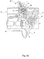
- FIGS. 4 a to 4 g show a manual closure cycle, alternatively with new contacts and worn contacts.
- the hand lever is shown in its right position, in abutment against one of the lateral edges of an opening in the casing B allowing passage of the lever ( 20 ), the contacts ( 6 ) and ( 9 ) then being separated.
- the finger ( 16 ) which is fixedly attached to the contact ( 6 )
- the magnetic actuator (M) is shown diagrammatically, only the striker, the fixed core and the movable core being shown, with the induction coil omitted.
- the striker For opening of the circuit breaker due to a short circuit, the striker is propelled against the trip ( 10 ), which causes the toggle system to swivel in order to open the contacts ( 6 , 9 ) as is, besides, well known.
- the movable electrical contact ( 6 ) has remained immobile, and at the same distance from the fixed electrical contact ( 9 ).
- the cam ( 12 ) is free to rotate about the spindle ( 19 )
- the projection ( 14 ) is rotated by one of the lateral edges of the aperture formed in the lower wall of the drum ( 21 ) and the cam therefore reflects the effort which is applied to the hand operating lever ( 1 ).
- FIGS. 5 a to 5 e show a reverse cycle, i.e. one by which the contacts ( 6 , 9 ) are opened.
- FIGS. 5 a to 5 b are therefore identical to FIGS. 4 f and 4 g, and must here be seen as the start of the opening cycle.
- the toggle operating mechanism actuates the contact support ( 2 ), and consequently the contact ( 6 ), in rotation in the counterclockwise direction.
- the contrary directions of the rotations already observed in the closure cycle, have occasioned an intersection of the trajectories, which places the finger ( 16 ) in the opening trajectory of the projection ( 14 ). If the opening has to be forced, the engagement of the projection ( 14 ) and the finger ( 16 ) could cause damage to one or other of these components, or even premature wear prejudicial to operation.
- the hand lever can again be brought into abutment against the opposite side of the upper opening in the casing D, in the position of opening of the contacts ( 6 , 9 ).
Landscapes
- Driving Mechanisms And Operating Circuits Of Arc-Extinguishing High-Tension Switches (AREA)
- Mechanisms For Operating Contacts (AREA)
- Breakers (AREA)
- Switch Cases, Indication, And Locking (AREA)
- Toys (AREA)
Applications Claiming Priority (3)
| Application Number | Priority Date | Filing Date | Title |
|---|---|---|---|
| EP00440285A EP1170769B1 (de) | 2000-10-19 | 2000-10-19 | Schnelleinschaltvorrichtung für Modulschutzschalter |
| EP00440285.5 | 2000-10-19 | ||
| EP00440285 | 2000-10-19 |
Publications (2)
| Publication Number | Publication Date |
|---|---|
| US20020046940A1 US20020046940A1 (en) | 2002-04-25 |
| US6492607B2 true US6492607B2 (en) | 2002-12-10 |
Family
ID=8174178
Family Applications (1)
| Application Number | Title | Priority Date | Filing Date |
|---|---|---|---|
| US09/782,876 Expired - Lifetime US6492607B2 (en) | 2000-10-19 | 2001-02-13 | Rapid closure mechanism for electrical contacts |
Country Status (6)
| Country | Link |
|---|---|
| US (1) | US6492607B2 (de) |
| EP (1) | EP1170769B1 (de) |
| AT (1) | ATE214516T1 (de) |
| DE (1) | DE60000091T2 (de) |
| ES (1) | ES2172499T3 (de) |
| PT (1) | PT1170769E (de) |
Cited By (15)
| Publication number | Priority date | Publication date | Assignee | Title |
|---|---|---|---|---|
| US6667680B1 (en) * | 2002-06-27 | 2003-12-23 | Eaton Corporation | Circuit breaker |
| US6800823B1 (en) * | 2003-10-24 | 2004-10-05 | Eaton Corporation | Circuit breaker including lever for snap close operation |
| US6800824B1 (en) * | 2003-10-24 | 2004-10-05 | Eaton Corporation | Circuit breaker including frame having stop for operating mechanism link |
| US6803536B1 (en) * | 2003-10-24 | 2004-10-12 | Eaton Corporation | Circuit breaker including independent link to operating handle |
| US6812422B1 (en) * | 2003-10-24 | 2004-11-02 | Eaton Corporation | Circuit breaker including a flexible cantilever lever for snap close operation |
| US6812423B1 (en) * | 2003-10-24 | 2004-11-02 | Eaton Corporation | Circuit breaker including lock for operating mechanism linkage |
| US6864451B1 (en) * | 2003-10-24 | 2005-03-08 | Eaton Corporation | Circuit breaker including operating handle having one or more operating arms and extension springs |
| US6870115B1 (en) * | 2003-10-24 | 2005-03-22 | Eaton Corporation | Circuit breaker including extension spring(s) between operating mechanism pivot and operating handle |
| US20050061648A1 (en) * | 2003-09-23 | 2005-03-24 | Moeller Gebaudeautomation Kg | Switch |
| US20060001511A1 (en) * | 2004-07-05 | 2006-01-05 | Abb Schweiz Ag | Moving contact unit for a contact arrangement in a circuit breaker |
| US20080001687A1 (en) * | 2004-11-18 | 2008-01-03 | Abb Patent Gmbh | Electrical Installation Switching Device |
| US20080290971A1 (en) * | 2007-05-23 | 2008-11-27 | Abb Ag | Electrical service switching device |
| CN100442420C (zh) * | 2004-09-30 | 2008-12-10 | 三菱电机株式会社 | 回路遮断路 |
| US20130161169A1 (en) * | 2011-12-21 | 2013-06-27 | Andrew Lawrence Gottschalk | Electrical switching apparatus and trip latch assembly therefor |
| AU2012311345B2 (en) * | 2011-09-22 | 2016-01-07 | Hager-Electro Sas | Electrical line protection device provided with means of indicating an electrical fault on the line |
Families Citing this family (10)
| Publication number | Priority date | Publication date | Assignee | Title |
|---|---|---|---|---|
| ATE443921T1 (de) * | 2006-02-03 | 2009-10-15 | Hager Electro Sas | Schaltschloss mit beweglicher drehachse |
| CN101882545A (zh) * | 2009-05-04 | 2010-11-10 | 上海良信电器股份有限公司 | 用于小型断路器的快速闭合机构 |
| FR2998413B1 (fr) * | 2012-11-21 | 2016-02-05 | Alstom Technology Ltd | Dispositif de commande a ressort pour un disjoncteur |
| CN103050342B (zh) * | 2012-12-20 | 2014-10-15 | 李敏 | 一种断路器操作机构和断路器 |
| CN103681139B (zh) * | 2014-01-02 | 2015-12-09 | 浙江德隆电器有限公司 | 一种断路器 |
| CN106935451B (zh) * | 2015-12-30 | 2019-04-30 | 三信国际电器上海有限公司 | 一种合闸装置及具有该装置的剩余电流动作断路器 |
| US10984974B2 (en) * | 2018-12-20 | 2021-04-20 | Schneider Electric USA, Inc. | Line side power, double break, switch neutral electronic circuit breaker |
| CN111710539A (zh) * | 2020-07-20 | 2020-09-25 | 上海瑞忒尔电气技术有限公司 | 一种开关装置的触头系统 |
| CN113745068B (zh) * | 2021-08-05 | 2023-11-24 | 杭州泰姆电气有限公司 | 断路器的操作机构 |
| CN117153609B (zh) * | 2022-05-24 | 2026-02-03 | 上海正泰智能科技有限公司 | 操作机构和隔离开关 |
Citations (4)
| Publication number | Priority date | Publication date | Assignee | Title |
|---|---|---|---|---|
| US4392036A (en) * | 1980-08-29 | 1983-07-05 | Siemens Aktiengesellschaft | Low-voltage protective circuit breaker with a forked locking lever |
| FR2581791A1 (fr) | 1985-05-13 | 1986-11-14 | Merlin Gerin | Mecanisme de fermeture manuelle brusque d'un appareil de coupure de courant |
| EP0224396A1 (de) | 1985-10-31 | 1987-06-03 | Merlin Gerin | Steuermechanismus für Niederspannungslastschalter |
| EP0897186A2 (de) | 1997-08-14 | 1999-02-17 | Siemens Aktiengesellschaft | Schaltmechanismus für einen Schulzschalter |
-
2000
- 2000-10-19 DE DE60000091T patent/DE60000091T2/de not_active Expired - Lifetime
- 2000-10-19 PT PT00440285T patent/PT1170769E/pt unknown
- 2000-10-19 AT AT00440285T patent/ATE214516T1/de active
- 2000-10-19 EP EP00440285A patent/EP1170769B1/de not_active Expired - Lifetime
- 2000-10-19 ES ES00440285T patent/ES2172499T3/es not_active Expired - Lifetime
-
2001
- 2001-02-13 US US09/782,876 patent/US6492607B2/en not_active Expired - Lifetime
Patent Citations (6)
| Publication number | Priority date | Publication date | Assignee | Title |
|---|---|---|---|---|
| US4392036A (en) * | 1980-08-29 | 1983-07-05 | Siemens Aktiengesellschaft | Low-voltage protective circuit breaker with a forked locking lever |
| FR2581791A1 (fr) | 1985-05-13 | 1986-11-14 | Merlin Gerin | Mecanisme de fermeture manuelle brusque d'un appareil de coupure de courant |
| US4687891A (en) | 1985-05-13 | 1987-08-18 | Merlin Gerin | Fast manual closing mechanism of a miniature circuit breaker |
| EP0224396A1 (de) | 1985-10-31 | 1987-06-03 | Merlin Gerin | Steuermechanismus für Niederspannungslastschalter |
| US4740770A (en) | 1985-10-31 | 1988-04-26 | Merlin Gerin | Operating mechanism for a low voltage electrical circuit breaker |
| EP0897186A2 (de) | 1997-08-14 | 1999-02-17 | Siemens Aktiengesellschaft | Schaltmechanismus für einen Schulzschalter |
Cited By (24)
| Publication number | Priority date | Publication date | Assignee | Title |
|---|---|---|---|---|
| US6667680B1 (en) * | 2002-06-27 | 2003-12-23 | Eaton Corporation | Circuit breaker |
| US20040000469A1 (en) * | 2002-06-27 | 2004-01-01 | Gibson Jeffrey S. | Circuit breaker |
| US7115829B2 (en) * | 2003-09-23 | 2006-10-03 | Moeller Gebäudeautomation KG | Switch |
| US20050061648A1 (en) * | 2003-09-23 | 2005-03-24 | Moeller Gebaudeautomation Kg | Switch |
| US6812423B1 (en) * | 2003-10-24 | 2004-11-02 | Eaton Corporation | Circuit breaker including lock for operating mechanism linkage |
| US6800823B1 (en) * | 2003-10-24 | 2004-10-05 | Eaton Corporation | Circuit breaker including lever for snap close operation |
| US6803536B1 (en) * | 2003-10-24 | 2004-10-12 | Eaton Corporation | Circuit breaker including independent link to operating handle |
| US6864451B1 (en) * | 2003-10-24 | 2005-03-08 | Eaton Corporation | Circuit breaker including operating handle having one or more operating arms and extension springs |
| US6870115B1 (en) * | 2003-10-24 | 2005-03-22 | Eaton Corporation | Circuit breaker including extension spring(s) between operating mechanism pivot and operating handle |
| US6800824B1 (en) * | 2003-10-24 | 2004-10-05 | Eaton Corporation | Circuit breaker including frame having stop for operating mechanism link |
| US6812422B1 (en) * | 2003-10-24 | 2004-11-02 | Eaton Corporation | Circuit breaker including a flexible cantilever lever for snap close operation |
| US7132912B2 (en) | 2004-07-05 | 2006-11-07 | Abb Schweiz Ag | Moving contact unit for a contact arrangement in a circuit breaker |
| EP1615252A1 (de) * | 2004-07-05 | 2006-01-11 | ABB Schweiz AG | Bewegliche Kontakteinheit für eine Kontaktanordnung eines Schutzschalters |
| US20060001511A1 (en) * | 2004-07-05 | 2006-01-05 | Abb Schweiz Ag | Moving contact unit for a contact arrangement in a circuit breaker |
| CN100442420C (zh) * | 2004-09-30 | 2008-12-10 | 三菱电机株式会社 | 回路遮断路 |
| US20080001687A1 (en) * | 2004-11-18 | 2008-01-03 | Abb Patent Gmbh | Electrical Installation Switching Device |
| US7579933B2 (en) * | 2004-11-18 | 2009-08-25 | Abb Patent Gmbh | Electrical installation switching device |
| US20080290971A1 (en) * | 2007-05-23 | 2008-11-27 | Abb Ag | Electrical service switching device |
| US7839241B2 (en) * | 2007-05-23 | 2010-11-23 | Abb Ag | Electrical service switching device |
| AU2012311345B2 (en) * | 2011-09-22 | 2016-01-07 | Hager-Electro Sas | Electrical line protection device provided with means of indicating an electrical fault on the line |
| US20130161169A1 (en) * | 2011-12-21 | 2013-06-27 | Andrew Lawrence Gottschalk | Electrical switching apparatus and trip latch assembly therefor |
| US8563887B2 (en) * | 2011-12-21 | 2013-10-22 | Eaton Corporation | Electrical switching apparatus and trip latch assembly therefor |
| CN104040671A (zh) * | 2011-12-21 | 2014-09-10 | 伊顿公司 | 电气开关装置及其解扣闩锁组件 |
| CN104040671B (zh) * | 2011-12-21 | 2018-11-09 | 伊顿公司 | 电气开关装置及其解扣闩锁组件 |
Also Published As
| Publication number | Publication date |
|---|---|
| US20020046940A1 (en) | 2002-04-25 |
| PT1170769E (pt) | 2002-07-31 |
| ES2172499T3 (es) | 2002-10-01 |
| DE60000091T2 (de) | 2002-11-07 |
| EP1170769A1 (de) | 2002-01-09 |
| ATE214516T1 (de) | 2002-03-15 |
| EP1170769B1 (de) | 2002-03-13 |
| DE60000091D1 (de) | 2002-04-18 |
Similar Documents
| Publication | Publication Date | Title |
|---|---|---|
| US6492607B2 (en) | Rapid closure mechanism for electrical contacts | |
| EP3567622B1 (de) | Doppelstromversorgungstransferschalter und schaltmechanismus dafür | |
| US9472359B2 (en) | Trip latch assemblies for circuit breakers and related circuit breakers | |
| JPH0210535B2 (de) | ||
| CN113782377A (zh) | 一种可快速切断的旋转开关 | |
| JP5581334B2 (ja) | 線路開閉装置用機械式トリップ装置 | |
| US20110179839A1 (en) | Latch assembly | |
| WO2015188314A1 (en) | Automatic transfer switch | |
| JPH10508150A (ja) | 低圧開閉装置用の切換えラッチ | |
| US20010022268A1 (en) | Circuit breaker motor drive | |
| JPH02192626A (ja) | 限流接触器用ロック機構 | |
| EP3561839B1 (de) | Schaltvorrichtung | |
| CN114823236B (zh) | 动作机构及旋转开关 | |
| JPH03500106A (ja) | 負荷時タップ切換器の切換開閉器用のスナップ動作ばね式駆動装置 | |
| JP2013501325A (ja) | バネ作動型機構を有する遅延回路 | |
| GB2058457A (en) | An electrical disconnecting switch | |
| CN113053689A (zh) | 一种用于旋转开关的快速切断结构 | |
| CN102782794B (zh) | 保护具有差分功能的电线路的锁定机构 | |
| JPH0136647B2 (de) | ||
| JP3278711B2 (ja) | 双投形インタロック装置 | |
| CN214477284U (zh) | 动作机构及旋转开关 | |
| US5772009A (en) | Operating mechanism for switches and fault interrupters | |
| GB2605853A (en) | Operating mechanism for a switch | |
| CN222637096U (zh) | 开关状态信号采集装置 | |
| HU219933B (hu) | Hajtáselrendezés vákuummegszakítókhoz, különösen hárompólusú kivitelben |
Legal Events
| Date | Code | Title | Description |
|---|---|---|---|
| AS | Assignment |
Owner name: HAGER ELECTRO, FRANCE Free format text: ASSIGNMENT OF ASSIGNORS INTEREST;ASSIGNORS:BRUCKERT, DIDIER;DIEBOLD, FRANCIS;DUEZ, OLIVIER;AND OTHERS;REEL/FRAME:011559/0073 Effective date: 20010118 |
|
| STCF | Information on status: patent grant |
Free format text: PATENTED CASE |
|
| FEPP | Fee payment procedure |
Free format text: PAYOR NUMBER ASSIGNED (ORIGINAL EVENT CODE: ASPN); ENTITY STATUS OF PATENT OWNER: LARGE ENTITY |
|
| FPAY | Fee payment |
Year of fee payment: 4 |
|
| FPAY | Fee payment |
Year of fee payment: 8 |
|
| FPAY | Fee payment |
Year of fee payment: 12 |