US6511015B1 - Method and apparatus for stabilizing the running of a web in a paper machine or a like - Google Patents
Method and apparatus for stabilizing the running of a web in a paper machine or a like Download PDFInfo
- Publication number
- US6511015B1 US6511015B1 US09/936,458 US93645801A US6511015B1 US 6511015 B1 US6511015 B1 US 6511015B1 US 93645801 A US93645801 A US 93645801A US 6511015 B1 US6511015 B1 US 6511015B1
- Authority
- US
- United States
- Prior art keywords
- suction
- web
- blow
- gas
- unit
- Prior art date
- Legal status (The legal status is an assumption and is not a legal conclusion. Google has not performed a legal analysis and makes no representation as to the accuracy of the status listed.)
- Expired - Fee Related
Links
- 238000000034 method Methods 0.000 title claims abstract description 10
- 230000000087 stabilizing effect Effects 0.000 title claims abstract 4
- 239000007789 gas Substances 0.000 claims abstract description 102
- 239000000567 combustion gas Substances 0.000 claims abstract description 7
- 238000001035 drying Methods 0.000 claims description 9
- 238000007664 blowing Methods 0.000 claims description 2
- 238000011144 upstream manufacturing Methods 0.000 claims 10
- 230000000694 effects Effects 0.000 description 6
- 239000000123 paper Substances 0.000 description 6
- 239000011248 coating agent Substances 0.000 description 3
- 238000000576 coating method Methods 0.000 description 3
- 230000003019 stabilising effect Effects 0.000 description 3
- 230000007423 decrease Effects 0.000 description 2
- 238000001704 evaporation Methods 0.000 description 2
- 230000008020 evaporation Effects 0.000 description 2
- 238000011010 flushing procedure Methods 0.000 description 2
- 238000010438 heat treatment Methods 0.000 description 2
- 238000001816 cooling Methods 0.000 description 1
- 230000003247 decreasing effect Effects 0.000 description 1
- 230000001627 detrimental effect Effects 0.000 description 1
- 239000011888 foil Substances 0.000 description 1
- 239000011087 paperboard Substances 0.000 description 1
Images


Classifications
-
- F—MECHANICAL ENGINEERING; LIGHTING; HEATING; WEAPONS; BLASTING
- F26—DRYING
- F26B—DRYING SOLID MATERIALS OR OBJECTS BY REMOVING LIQUID THEREFROM
- F26B3/00—Drying solid materials or objects by processes involving the application of heat
- F26B3/28—Drying solid materials or objects by processes involving the application of heat by radiation, e.g. from the sun
- F26B3/30—Drying solid materials or objects by processes involving the application of heat by radiation, e.g. from the sun from infrared-emitting elements
- F26B3/305—Drying solid materials or objects by processes involving the application of heat by radiation, e.g. from the sun from infrared-emitting elements the infrared radiation being generated by combustion or combustion gases
-
- B—PERFORMING OPERATIONS; TRANSPORTING
- B65—CONVEYING; PACKING; STORING; HANDLING THIN OR FILAMENTARY MATERIAL
- B65H—HANDLING THIN OR FILAMENTARY MATERIAL, e.g. SHEETS, WEBS, CABLES
- B65H23/00—Registering, tensioning, smoothing or guiding webs
- B65H23/04—Registering, tensioning, smoothing or guiding webs longitudinally
- B65H23/24—Registering, tensioning, smoothing or guiding webs longitudinally by fluid action, e.g. to retard the running web
-
- D—TEXTILES; PAPER
- D21—PAPER-MAKING; PRODUCTION OF CELLULOSE
- D21F—PAPER-MAKING MACHINES; METHODS OF PRODUCING PAPER THEREON
- D21F5/00—Dryer section of machines for making continuous webs of paper
- D21F5/001—Drying webs by radiant heating
- D21F5/002—Drying webs by radiant heating from infrared-emitting elements
-
- D—TEXTILES; PAPER
- D21—PAPER-MAKING; PRODUCTION OF CELLULOSE
- D21F—PAPER-MAKING MACHINES; METHODS OF PRODUCING PAPER THEREON
- D21F5/00—Dryer section of machines for making continuous webs of paper
- D21F5/18—Drying webs by hot air
- D21F5/185—Supporting webs in hot air dryers
- D21F5/187—Supporting webs in hot air dryers by air jets
-
- F—MECHANICAL ENGINEERING; LIGHTING; HEATING; WEAPONS; BLASTING
- F26—DRYING
- F26B—DRYING SOLID MATERIALS OR OBJECTS BY REMOVING LIQUID THEREFROM
- F26B13/00—Machines and apparatus for drying fabrics, fibres, yarns, or other materials in long lengths, with progressive movement
- F26B13/10—Arrangements for feeding, heating or supporting materials; Controlling movement, tension or position of materials
- F26B13/101—Supporting materials without tension, e.g. on or between foraminous belts
- F26B13/104—Supporting materials without tension, e.g. on or between foraminous belts supported by fluid jets only; Fluid blowing arrangements for flotation dryers, e.g. coanda nozzles
-
- F—MECHANICAL ENGINEERING; LIGHTING; HEATING; WEAPONS; BLASTING
- F26—DRYING
- F26B—DRYING SOLID MATERIALS OR OBJECTS BY REMOVING LIQUID THEREFROM
- F26B3/00—Drying solid materials or objects by processes involving the application of heat
- F26B3/28—Drying solid materials or objects by processes involving the application of heat by radiation, e.g. from the sun
- F26B3/283—Drying solid materials or objects by processes involving the application of heat by radiation, e.g. from the sun in combination with convection
-
- B—PERFORMING OPERATIONS; TRANSPORTING
- B65—CONVEYING; PACKING; STORING; HANDLING THIN OR FILAMENTARY MATERIAL
- B65H—HANDLING THIN OR FILAMENTARY MATERIAL, e.g. SHEETS, WEBS, CABLES
- B65H2515/00—Physical entities not provided for in groups B65H2511/00 or B65H2513/00
- B65H2515/50—Vibrations; Oscillations
-
- B—PERFORMING OPERATIONS; TRANSPORTING
- B65—CONVEYING; PACKING; STORING; HANDLING THIN OR FILAMENTARY MATERIAL
- B65H—HANDLING THIN OR FILAMENTARY MATERIAL, e.g. SHEETS, WEBS, CABLES
- B65H2601/00—Problem to be solved or advantage achieved
- B65H2601/50—Diminishing, minimizing or reducing
- B65H2601/52—Diminishing, minimizing or reducing entities relating to handling machine
- B65H2601/524—Vibration
Definitions
- the present invention relates to a method and a device defined below in the introductory parts of the independent claims for stabilising the web run in a paper machine or the like.
- the invention relates typically to a method and a device for stabilising the web run in a paper machine or the like where the web is heated and/or dried by gas infras or the like.
- blow suction modules are arranged in connection with the gas infras, typically between the gas infras, in order to stabilise the web run, to improve the runnability, to make the heat and mass transfer more effective, to prevent the web from touching the gas infra structures, to utilise the exhaust gases of the gas infra for drying and for stabilising the web run, and/or to remove combustion gas from the web area.
- a typical blow suction module or box comprises
- blow nozzle unit such as a Float or Foil nozzle of the applicant, which has at least one gap nozzle extending mainly across the web or a corresponding nozzle arrangement extending mainly across the web,
- a first air discharge unit extending mainly across the web and being arranged on the front side of the blow nozzle unit, as seen in the travel direction of the web, and having a suction nozzle extending mainly across the web or some other corresponding suction arrangement extending across the web, and
- a second air discharge unit extending mainly across the web and being arranged on the back side of the blow nozzle unit, as seen in the travel direction of the web, and having a suction nozzle extending mainly across the web or some other corresponding suction arrangement extending across the web.
- the blow nozzle unit or units of the blow suction module blow a gas against the surface of the web, such as combustion gas sucked from the gas infras adjacent to the blow suction unit, air sucked from the web area, replacement air, or other air or gas.
- the blow nozzle unit comprises a nozzle surface which is parallel to the web and in the connection of which there are arranged the actual blow nozzles, such as one or more gap nozzles or a row of nozzle openings extending across the web, from which nozzles gas can be blown against the web in a desired manner.
- the air discharge unit or units of the blow suction module are arranged to suck gas, such as air and/or gas discharged from the gas infras, from the region between the air discharge unit and the web.
- the air discharge units comprise typically a bottom plate or a corresponding surface, to which there are arranged one or more suction gaps or suction nozzles, such as suction openings.
- the suction zones on each side of the blow nozzle unit are thus mainly arranged to suck back air which is blown from the nozzle, and combustion gas which is blown from the adjacent gas infra or the like, and/or flushing gases used in the infra, which thus can be returned to be utilised again. Further the blow nozzle unit sucks air transported by the web.
- Disadvantageous blowing and suction arrangements can cause flutter in the web and thus impair the runnability.
- the fluttering may cause the web to touch the gas infra, which easily results in a web break or which may cause a danger of fire.
- the gas infras further tend to react on the air flow created between them and the web, in which case the air flow easily interferes with the function of the radiator in the gas infra.
- the air flows hitting the radiator element decrease the efficiency of the radiator and they may even extinguish the flame of the infra radiator.
- the object of the present invention is to provide an improvement regarding the above presented problems in a paper machine or the like.
- One object of the invention is then to optimise the flow field in the region of the blow suction modules so that the creation of detrimental flows is prevented.
- An object of the invention is also to improve the efficiency of gas infras or the like used in paper machines or the like, by minimising the air flows hitting the radiators.
- asymmetric blow suction modules i.e. modules having a air discharge unit on the front side which sucks more gas than that on the back side, the flutter and vibration can be substantially decreased.
- the aim is to optimise the flow field around the blow nozzle with the aid of an asymmetric control or structure of the air discharge units, so that the air flows disturbing the web run are minimised and an optimal runnability is achieved. This is particularly useful, especially at high web speeds.
- a nozzle module according to the invention can be particularly advantageously used in connection with an infra dryer as a system which stabilises the web and effectivates the evaporation.
- the solution according to the invention enables the use of over-pressure nozzles in the gas infra drying in order to improve the runnability and to effectivate the heat and mass transfer. Then there are suction zones on both sides of the nozzles, through which zones both air blown from the over-pressure nozzles and combustion gas of the infra radiator and/or flushing air is sucked back. According to the invention these gases and air flows can be sucked back smoothly without causing problems. In this way the web flutter is avoided, and in addition also harmful air flows directed at the infra radiator are avoided.
- the suction is typically arranged to be asymmetric, so that the larger part of the sucked air and/or gas is discharged at the entry side of the blow suction module, and the smaller part at the exit side.
- An asymmetric suction can be provided for instance so that the air discharge unit or the suction zone of the blow suction module is smaller at the exit side than at the entry side of the module.
- An asymmetric suction can be provided also by control dampers, with which the negative pressure in the different air discharge units can be controlled to have different magnitudes. Then the negative pressure at the entry side is typically controlled to be greater than at the exit side.
- the invention can be advantageously used in paper machines or in other corresponding machines, such as in paper board machines, in coating machines, in other finishing machines and in machines for further processing, where the heating and/or drying of the web is made at least partly by gas infras.
- the invention is particularly well suited to be used in coating machines for heating and drying the coated web immediately after the coating.
- the invention can also be applied otherwise than in connection with gas infras.
- An asymmetric blow suction module according to the invention can be used e.g. for cooling and evaporation when a good runnability and web stability is required.
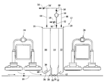
- FIG. 1 shows schematically a cross section taken in the web direction of an exemplary blow suction module according to the invention mounted between two gas infras,
- FIGS. 2 a , 2 b and 2 c show according to FIG. 1 three different blow suction module solutions according to the invention
- FIGS. 3 a and 3 b show as a function of time the flutter of a web being dried, measured between two blow suction modules, in a drier which does not use the solution according to the invention, and in a drier which uses the solution according to the invention, respectively, and
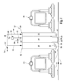
- FIG. 4 shows schematically a drier where a number of consecutive blow suction modules according to the invention are mounted on both sides of the web.
- FIG. 1 shows an asymmetric blow suction module 12 according to the invention which is mounted above the web 10 of a paper machine, which module comprises a blow nozzle unit 14 having a first discharge suction unit 18 arranged on the front side 16 and a second discharge suction unit 22 on the back side 20 .
- the blow suction module 12 is arranged between two gas infra modules 24 and 26 .
- the blow nozzle unit 14 is a Float over-pressure nozzle of the applicant, having against the web a bottom part 28 which has two nozzles or nozzle gaps 30 , 32 on its sides in the transversal direction of the web, which nozzles are arranged to blow gas and/or air against each other along the nozzle surface 34 of the nozzle.
- the nozzle surface is convex, so that due to the so called Coanda effect the air jets blown from the nozzle gaps follow at least a short distance the nozzle surface, after which the air jets turn downwards against the web and eventually outwards, i.e. towards the air discharge units.
- the air jets blown from the nozzle gaps are typically discharged into different directions, the jets from the first nozzle 30 towards the first air discharge unit 18 and the jets from the second nozzle towards the second air discharge unit 22 .
- the first air discharge unit 18 is dimensioned to be so large that it is able to suck the gas and/or air coming from the first gas infra in a suitable manner.
- the second air discharge unit 22 is dimensioned to be so small that it will not tend to suck so much gas and/or air from the region of the second gas infra 26 , that it would create in this region, or between the second gas infra 26 and the second air discharge unit 22 , a flow which is harmful to the radiator.
- both air discharge units have been provided with bottom plates 40 , 42 , which are bent downwards into a V-shape and which contain suction openings 38 .
- bottom plates 40 , 42 which are bent downwards into a V-shape and which contain suction openings 38 .
- the blow nozzle unit there is thus formed a space which tapers upward, and from which gas and/or air is sucked through the suction openings 38 into these units 18 , 22 .
- the air discharge unit 18 and its bottom plate 40 are larger than the second air discharge unit 22 and its bottom plate 42 .
- the total open area of the suction openings 38 in the bottom plate 40 is larger than the corresponding total open area of the suction openings of the corresponding second bottom plate 42 .
- the suction effect of the first air discharge unit 18 is substantially larger than the suction effect of the second air discharge unit 22 .
- FIG. 1 shows also schematically the passage of the air/gas from the air discharge units 18 , 22 to the blow nozzle unit 14 .
- the air flows 44 , 46 of both air discharge units are combined into a common air flow 48 , which with the blower 50 is directed via the channel 52 into the blow nozzle unit 14 .
- Additional air can be supplied through the channel 54 for instance into the common air flow 48 .
- Excessive gas/air can be removed through the channel 56 .
- With the valves 54 ′ and 56 ′ it is possible to control the supply of additional air and the removal of air.
- With the valve 58 or with the blower 50 it is on the other hand possible to control the suction effect of the air discharge units 18 , 22 , when required.
- FIG. 1 shows a solution where the air removed by the discharge suction units 18 , 22 from the web area is returned by the channels 44 , 46 , 48 , 52 and the blower 50 into the blow nozzle unit 14 of the same blow suction module 12 . It is of course possible to connect these channels and the blower to a plurality of blow suction modules. Then the air flows discharged from the plurality of blow suction modules can be combined and directed by the same blower into the blow nozzle unit of the plurality of blow suction modules. It is of course also possible to arrange the passage of gas and/or air in other ways.
- FIGS. 2 a , 2 b and 2 c show blow suction modules 12 with a bottom geometry of the discharge suction units differing from that shown in FIG. 1 .
- the bottom plates 40 , 42 of the discharge suction units 18 , 22 are parallel with the web to be dried.
- the area of the bottom plate of the discharge suction unit on the front side, as well as the total open area of the suction openings 38 in this bottom plate, is larger than the corresponding areas of the discharge suction unit on the back side.
- FIG. 2 b the bottom plates of the discharge suction units 18 , 22 are upwards inclined toward the centre of the blow suction modules.
- the bottom plate 40 on the front side has a larger area than the bottom plate on the back side.
- the bottom plates of the discharge suction units 18 , 22 are downwards inclined towards the centre of the blow suction modules.
- FIG. 3 a shows as a function of time the flutter of a web being dried, measured between two adjacent modules, in a drier which blow suction module uses air discharge units of the same size, i.e. symmetrical units, on the front and the back sides of the blow suction module.
- FIG. 3 b shows the corresponding web flutter in a drying solution which uses an asymmetric blow suction module according to the invention, i.e. where air discharge units of different sizes are used on the front and the back sides.
- the asymmetric air discharge units will considerably reduce the flutter of the web.
- FIG. 1 shows a blow suction module according to the invention when it is mounted above the web.
- Corresponding modules can be mounted below the web, when desired.
- the modules can be mounted directly against each other on different sides of the web, or in a zig-zag pattern, as shown in FIG. 4 .
- a module is mounted under the web in the middle between two modules above the web.
Landscapes
- Engineering & Computer Science (AREA)
- General Engineering & Computer Science (AREA)
- Mechanical Engineering (AREA)
- Chemical & Material Sciences (AREA)
- Life Sciences & Earth Sciences (AREA)
- Microbiology (AREA)
- Combustion & Propulsion (AREA)
- Textile Engineering (AREA)
- Drying Of Solid Materials (AREA)
- Paper (AREA)
- Preliminary Treatment Of Fibers (AREA)
- Replacement Of Web Rolls (AREA)
- Advancing Webs (AREA)
Applications Claiming Priority (3)
| Application Number | Priority Date | Filing Date | Title |
|---|---|---|---|
| FI990605A FI105936B (fi) | 1999-03-18 | 1999-03-18 | Menetelmä ja laite radan kulun stabiloimiseksi paperikoneessa tai vastaavassa |
| FI990605 | 1999-03-18 | ||
| PCT/FI2000/000214 WO2000058551A1 (fr) | 1999-03-18 | 2000-03-17 | Procede et dispositif de stabilisation du deplacement d'une bande de papier dans une machine a papier ou analogue |
Publications (1)
| Publication Number | Publication Date |
|---|---|
| US6511015B1 true US6511015B1 (en) | 2003-01-28 |
Family
ID=8554227
Family Applications (1)
| Application Number | Title | Priority Date | Filing Date |
|---|---|---|---|
| US09/936,458 Expired - Fee Related US6511015B1 (en) | 1999-03-18 | 2000-03-17 | Method and apparatus for stabilizing the running of a web in a paper machine or a like |
Country Status (8)
| Country | Link |
|---|---|
| US (1) | US6511015B1 (fr) |
| EP (1) | EP1169511B1 (fr) |
| AT (1) | ATE280267T1 (fr) |
| AU (1) | AU3436200A (fr) |
| CA (1) | CA2365683C (fr) |
| DE (1) | DE60015108T2 (fr) |
| FI (1) | FI105936B (fr) |
| WO (1) | WO2000058551A1 (fr) |
Cited By (6)
| Publication number | Priority date | Publication date | Assignee | Title |
|---|---|---|---|---|
| US20070125876A1 (en) * | 2005-07-28 | 2007-06-07 | Ralf Bolling | Nozzle system for the treatment of web-shaped material |
| WO2007085617A1 (fr) * | 2006-01-25 | 2007-08-02 | Nv Bekaert Sa | Secheur a flamme |
| CN101375121B (zh) * | 2006-01-25 | 2010-12-01 | 贝卡尔特股份有限公司 | 干燥器设备的对流系统 |
| WO2018046510A1 (fr) * | 2016-09-08 | 2018-03-15 | Solaronics S.A. | Système combiné à convection et rayonnement pour le traitement thermique d'une bande continue |
| CN109863272A (zh) * | 2016-09-08 | 2019-06-07 | 索拉劳尼克斯股份有限公司 | 用于连续条料的热处理的对流罩 |
| JP2021522060A (ja) * | 2018-05-04 | 2021-08-30 | ヘレーウス ノーブルライト ゲゼルシャフト ミット ベシュレンクテル ハフツングHeraeus Noblelight GmbH | 基材を乾燥させるための方法、空気乾燥モジュールおよび乾燥システム |
Families Citing this family (4)
| Publication number | Priority date | Publication date | Assignee | Title |
|---|---|---|---|---|
| DE102007051963A1 (de) | 2007-10-31 | 2009-05-07 | Voith Patent Gmbh | Materialbahntrockneranordnung |
| DE102007051962A1 (de) | 2007-10-31 | 2009-05-07 | Voith Patent Gmbh | Materialbahntrockneranordnung |
| DE102008042247A1 (de) | 2008-09-22 | 2010-04-01 | Voith Patent Gmbh | Materialbahntrockneranordnung |
| DE102008042248A1 (de) | 2008-09-22 | 2010-04-01 | Voith Patent Gmbh | Materialbahntrockneranordnung |
Citations (12)
| Publication number | Priority date | Publication date | Assignee | Title |
|---|---|---|---|---|
| US3680223A (en) * | 1969-10-11 | 1972-08-01 | Vits Gmbh Maschbau | Apparatus for a non-contacting directional control of a web |
| US3837551A (en) * | 1972-06-19 | 1974-09-24 | Midland Ross Corp | Web conveying and treating method and apparatus |
| US4137644A (en) | 1975-12-09 | 1979-02-06 | Aktiebolaget Svenska Flaktfabriken | Treating airborne web material |
| US4384666A (en) | 1980-03-28 | 1983-05-24 | Valmet Oy | Nozzle apparatus for handling web material |
| US4881327A (en) | 1988-03-10 | 1989-11-21 | J. M. Voith Gmbh | Dryer section |
| US4893416A (en) | 1987-07-07 | 1990-01-16 | Hilmar Vits | Apparatus for the contactless guiding of webs of material |
| US4932140A (en) | 1987-09-28 | 1990-06-12 | Valmet Paper Machinery Inc. | Arrangement of pressure nozzles for the treatment of webs |
| US5014447A (en) * | 1988-02-10 | 1991-05-14 | Thermo Electron Web Systems, Inc. | Positive pressure web floater dryer with parallel flow |
| US5752641A (en) * | 1996-02-08 | 1998-05-19 | Vits-Maschinenbau Gmbh | Suspension dryer, in particular offset dryer |
| US5829166A (en) * | 1996-05-15 | 1998-11-03 | Vits Maschinenbau Gmbh | Air-cushion nozzle for drying apparatus |
| US6088930A (en) * | 1997-11-14 | 2000-07-18 | Solaronics Process Sa | Convection-radiation system for heat treatment of a continuous strip |
| US6289603B1 (en) * | 1999-02-18 | 2001-09-18 | Solaronics Process Sa | Combined blowing and suction system with integral energy exchange for a drying installation |
-
1999
- 1999-03-18 FI FI990605A patent/FI105936B/fi active
-
2000
- 2000-03-17 CA CA002365683A patent/CA2365683C/fr not_active Expired - Fee Related
- 2000-03-17 AT AT00912701T patent/ATE280267T1/de not_active IP Right Cessation
- 2000-03-17 DE DE60015108T patent/DE60015108T2/de not_active Expired - Fee Related
- 2000-03-17 EP EP00912701A patent/EP1169511B1/fr not_active Expired - Lifetime
- 2000-03-17 US US09/936,458 patent/US6511015B1/en not_active Expired - Fee Related
- 2000-03-17 AU AU34362/00A patent/AU3436200A/en not_active Abandoned
- 2000-03-17 WO PCT/FI2000/000214 patent/WO2000058551A1/fr not_active Ceased
Patent Citations (12)
| Publication number | Priority date | Publication date | Assignee | Title |
|---|---|---|---|---|
| US3680223A (en) * | 1969-10-11 | 1972-08-01 | Vits Gmbh Maschbau | Apparatus for a non-contacting directional control of a web |
| US3837551A (en) * | 1972-06-19 | 1974-09-24 | Midland Ross Corp | Web conveying and treating method and apparatus |
| US4137644A (en) | 1975-12-09 | 1979-02-06 | Aktiebolaget Svenska Flaktfabriken | Treating airborne web material |
| US4384666A (en) | 1980-03-28 | 1983-05-24 | Valmet Oy | Nozzle apparatus for handling web material |
| US4893416A (en) | 1987-07-07 | 1990-01-16 | Hilmar Vits | Apparatus for the contactless guiding of webs of material |
| US4932140A (en) | 1987-09-28 | 1990-06-12 | Valmet Paper Machinery Inc. | Arrangement of pressure nozzles for the treatment of webs |
| US5014447A (en) * | 1988-02-10 | 1991-05-14 | Thermo Electron Web Systems, Inc. | Positive pressure web floater dryer with parallel flow |
| US4881327A (en) | 1988-03-10 | 1989-11-21 | J. M. Voith Gmbh | Dryer section |
| US5752641A (en) * | 1996-02-08 | 1998-05-19 | Vits-Maschinenbau Gmbh | Suspension dryer, in particular offset dryer |
| US5829166A (en) * | 1996-05-15 | 1998-11-03 | Vits Maschinenbau Gmbh | Air-cushion nozzle for drying apparatus |
| US6088930A (en) * | 1997-11-14 | 2000-07-18 | Solaronics Process Sa | Convection-radiation system for heat treatment of a continuous strip |
| US6289603B1 (en) * | 1999-02-18 | 2001-09-18 | Solaronics Process Sa | Combined blowing and suction system with integral energy exchange for a drying installation |
Cited By (11)
| Publication number | Priority date | Publication date | Assignee | Title |
|---|---|---|---|---|
| US20070125876A1 (en) * | 2005-07-28 | 2007-06-07 | Ralf Bolling | Nozzle system for the treatment of web-shaped material |
| WO2007085617A1 (fr) * | 2006-01-25 | 2007-08-02 | Nv Bekaert Sa | Secheur a flamme |
| WO2007085618A1 (fr) * | 2006-01-25 | 2007-08-02 | Nv Bekaert Sa | Systeme convectif pour installation de sechage |
| US20090007453A1 (en) * | 2006-01-25 | 2009-01-08 | Nv Bekaert Sa | Flame Dryer |
| US20090031581A1 (en) * | 2006-01-25 | 2009-02-05 | Nv Bekaert Sa | Convective system for a dryer installation |
| CN101375121B (zh) * | 2006-01-25 | 2010-12-01 | 贝卡尔特股份有限公司 | 干燥器设备的对流系统 |
| CN101375123B (zh) * | 2006-01-25 | 2011-06-08 | 贝卡尔特股份有限公司 | 火焰干燥器 |
| US8046934B2 (en) | 2006-01-25 | 2011-11-01 | Nv Bekaert Sa | Convective system for a dryer installation |
| WO2018046510A1 (fr) * | 2016-09-08 | 2018-03-15 | Solaronics S.A. | Système combiné à convection et rayonnement pour le traitement thermique d'une bande continue |
| CN109863272A (zh) * | 2016-09-08 | 2019-06-07 | 索拉劳尼克斯股份有限公司 | 用于连续条料的热处理的对流罩 |
| JP2021522060A (ja) * | 2018-05-04 | 2021-08-30 | ヘレーウス ノーブルライト ゲゼルシャフト ミット ベシュレンクテル ハフツングHeraeus Noblelight GmbH | 基材を乾燥させるための方法、空気乾燥モジュールおよび乾燥システム |
Also Published As
| Publication number | Publication date |
|---|---|
| ATE280267T1 (de) | 2004-11-15 |
| CA2365683A1 (fr) | 2000-10-05 |
| EP1169511B1 (fr) | 2004-10-20 |
| WO2000058551A1 (fr) | 2000-10-05 |
| CA2365683C (fr) | 2006-11-21 |
| AU3436200A (en) | 2000-10-16 |
| EP1169511A1 (fr) | 2002-01-09 |
| DE60015108D1 (de) | 2004-11-25 |
| DE60015108T2 (de) | 2006-03-02 |
| FI990605A0 (fi) | 1999-03-18 |
| FI105936B (fi) | 2000-10-31 |
Similar Documents
| Publication | Publication Date | Title |
|---|---|---|
| US4467537A (en) | Equipment for heat-treating flat, band-like lengths of material | |
| JP3305802B2 (ja) | ウエブ材の無接触空気乾燥方法並びに該方法によるノズル吹き出しボックス及びパルプドライヤ | |
| EP1015691B1 (fr) | Unite de sechage par flottation | |
| US6511015B1 (en) | Method and apparatus for stabilizing the running of a web in a paper machine or a like | |
| EP0195757B1 (fr) | Dispositif pour faire sécher un matériau en bande | |
| US12385693B2 (en) | Method for drying a substrate and air-drying module and drying system | |
| CA2377523C (fr) | Systeme de buse et procede d'amelioration du transfert de chaleur dans un dispositif de sechage de bande aeroportee | |
| JP4822036B2 (ja) | 乾燥装置 | |
| US20070107256A1 (en) | Device and method for drying a treated product | |
| JPH01168987A (ja) | 製紙機用シリンダドライヤの乾燥方法および装置 | |
| US7530179B2 (en) | Step air foil | |
| US4893416A (en) | Apparatus for the contactless guiding of webs of material | |
| US8061055B2 (en) | Step air foil web stabilizer | |
| JP7310054B2 (ja) | ボードを乾燥するための方法及び装置 | |
| US5857270A (en) | Open burner plenum for a flotation dryer | |
| FI129176B (en) | Arrangement and method for removing moisture from the pocket space of the drying section of a paper or board machine | |
| JP2000314070A (ja) | 経糸糊付け機の熱風乾燥装置 | |
| JPH07138657A (ja) | 連続的に通走する金属帯材を熱処理する方法および装置 | |
| US20020124429A1 (en) | Apparatus for ventilating a pocket of a dryer section of a paper machine | |
| JP2838360B2 (ja) | 熱処理装置 | |
| JPH0582541U (ja) | 乾燥器 | |
| JPH02502388A (ja) | 連続ストリップ形式の製品を熱処理するプラントにおける排気装置 |
Legal Events
| Date | Code | Title | Description |
|---|---|---|---|
| AS | Assignment |
Owner name: METSO PAPER, INC., FINLAND Free format text: ASSIGNMENT OF ASSIGNORS INTEREST;ASSIGNORS:HEIKKILA, PERTTI;HUHTALA, OLLI;KANKARE, HELI;AND OTHERS;REEL/FRAME:012364/0381;SIGNING DATES FROM 20010731 TO 20010807 |
|
| FEPP | Fee payment procedure |
Free format text: PAYOR NUMBER ASSIGNED (ORIGINAL EVENT CODE: ASPN); ENTITY STATUS OF PATENT OWNER: LARGE ENTITY |
|
| FPAY | Fee payment |
Year of fee payment: 4 |
|
| REMI | Maintenance fee reminder mailed | ||
| LAPS | Lapse for failure to pay maintenance fees | ||
| STCH | Information on status: patent discontinuation |
Free format text: PATENT EXPIRED DUE TO NONPAYMENT OF MAINTENANCE FEES UNDER 37 CFR 1.362 |
|
| FP | Lapsed due to failure to pay maintenance fee |
Effective date: 20110128 |
|
| AS | Assignment |
Owner name: VALMET TECHNOLOGIES, INC., FINLAND Free format text: CHANGE OF NAME;ASSIGNOR:METSO PAPER, INC.;REEL/FRAME:032551/0426 Effective date: 20131212 |