US6588264B1 - Pressure indicating devices - Google Patents
Pressure indicating devices Download PDFInfo
- Publication number
- US6588264B1 US6588264B1 US09/180,306 US18030699A US6588264B1 US 6588264 B1 US6588264 B1 US 6588264B1 US 18030699 A US18030699 A US 18030699A US 6588264 B1 US6588264 B1 US 6588264B1
- Authority
- US
- United States
- Prior art keywords
- pressure
- chamber
- indicating device
- diaphragm
- pressure indicating
- Prior art date
- Legal status (The legal status is an assumption and is not a legal conclusion. Google has not performed a legal analysis and makes no representation as to the accuracy of the status listed.)
- Expired - Fee Related
Links
- 230000000007 visual effect Effects 0.000 claims abstract description 8
- 230000011664 signaling Effects 0.000 claims description 17
- 230000009172 bursting Effects 0.000 claims description 3
- 238000004519 manufacturing process Methods 0.000 claims description 3
- 230000006835 compression Effects 0.000 description 3
- 238000007906 compression Methods 0.000 description 3
- 239000003086 colorant Substances 0.000 description 2
- 238000010276 construction Methods 0.000 description 2
- 238000001514 detection method Methods 0.000 description 2
- 239000007789 gas Substances 0.000 description 2
- 238000005259 measurement Methods 0.000 description 2
- 239000011324 bead Substances 0.000 description 1
- 230000015572 biosynthetic process Effects 0.000 description 1
- 230000000881 depressing effect Effects 0.000 description 1
- 230000009977 dual effect Effects 0.000 description 1
- 238000005755 formation reaction Methods 0.000 description 1
- 239000000446 fuel Substances 0.000 description 1
- 239000007788 liquid Substances 0.000 description 1
- 238000012806 monitoring device Methods 0.000 description 1
- 238000012544 monitoring process Methods 0.000 description 1
- 230000003287 optical effect Effects 0.000 description 1
- 238000005096 rolling process Methods 0.000 description 1
- 230000035945 sensitivity Effects 0.000 description 1
Images

Classifications
-
- B—PERFORMING OPERATIONS; TRANSPORTING
- B60—VEHICLES IN GENERAL
- B60C—VEHICLE TYRES; TYRE INFLATION; TYRE CHANGING; CONNECTING VALVES TO INFLATABLE ELASTIC BODIES IN GENERAL; DEVICES OR ARRANGEMENTS RELATED TO TYRES
- B60C23/00—Devices for measuring, signalling, controlling, or distributing tyre pressure or temperature, specially adapted for mounting on vehicles; Arrangement of tyre inflating devices on vehicles, e.g. of pumps or of tanks; Tyre cooling arrangements
- B60C23/02—Signalling devices actuated by tyre pressure
- B60C23/04—Signalling devices actuated by tyre pressure mounted on the wheel or tyre
- B60C23/0491—Constructional details of means for attaching the control device
- B60C23/0496—Valve stem attachments positioned outside of the tyre chamber
Definitions
- This invention relates to pressure indicating devices and particularly but not exclusively to such devices for indicating vehicle tyre pressure.
- pressure indicating devices have been known for some time, the majority being devices which provide a means to accurately measure pressure, particularly of gases and liquids.
- a precise measurement of pressure is not required but rather a simple and clear indication of a change in pressure is desired, for example to detect leakage from a pressurised container.
- a device which provides a highly visual “see-at-a-glance” indication that leakage is occurring is more appropriate than a precise numerical measurement of the pressure within the container.
- a device for indicating whether a pneumatic circuit is pressurised, available under the trade mark ROTOWINK (ex Norgren Martonair Limited).
- This device is adapted to be mounted on a control panel, with the inlet connected to part of a pneumatic circuit, e.g. a pressure vessel, such as a compressor reservoir.
- the device contains a flexible, impermeable diaphragm that spans the inlet.
- the diaphragm supports a spring returnable piston.
- a rod and crank arrangement extends from the piston, terminating in the head of the device, remote from the inlet, where the rod is attached to a crank within a rotatable ball having its opposite halves different colours, e.g. red and green.
- the ball is mounted beneath a lens through which one side of the ball is clearly visible from the exterior of the device.
- a difference in pressure across the diaphragm e.g. resulting from a build up of air pressure in a compression chamber to which the inlet of the device is connected, causes the diaphragm to flex towards the head of the device, which pushes the piston and rod towards the head. This movement causes the crank to cause the ball to rotate such that the other side of the ball is then visible through the lens.
- This other ball side of contrasting colour provides a clear visual signal that pressure has built up in the chamber.
- tyre pressures are checked at regular intervals.
- this mundane task is frequently overlooked since a lower than optimal tyre pressure, such as caused by a slow puncture or an inaccurate gauge on a pump or compressed air supply unit, is only perceived when the tyre looks dangerously flat and/or the vehicle feels uncomfortable, at which stage the tyre pressure is well below its optimum.
- any use of the vehicle reduces the life of the tyre significantly and will have put the driver and passengers of the vehicle at some risk.
- U.S. Pat. No. 4,814,745 describes a cap for attachment to a tyre valve following inflation and which includes an alarm circuit which is de-energised when the tyre is inflated to proper pressure.
- the cap must include its own power supply and other circuit members which is undesirably complex, prone to failure and expensive.
- U.S. Pat. No. 4,819,686 discloses a purely mechanical device including a diaphragm in a chamber.
- the diaphragm may be deflected to give a visual indication of the state of pressure within the tyre.
- One side of the diaphragm is a so-called reference chamber which, when the device is applied to a tyre valve stem, is pressurised to the pressure within the tyre. Thereafter the reference chamber is sealed while the other side of the diaphragm is exposed to the pressure within the tyre, so that if the latter drops, the diaphragm moves.
- the construction is relatively complex and the cap provides no indication as to whether the tyre is inflated to the correct pressure.
- British patent specification 2277802 discloses a similar device but in which an indication of the state of pressure in the tyre is achieved only with the use of a hand held device adapted to be brought into close proximity with the cap on the valve stem. It suffers from the same disadvantage as noted above.
- U.S. Pat. No. 2,689,481 describes a tyre pressure indicating device comprising a housing which may be screwed on to a tyre valve stem and which includes an inlet for air under pressure from the tyre into a transparent walled chamber.
- the chamber contains a hermetically sealed bellows, the degree of compression of which changes its length to provide, in conjunction with markings on the exterior of the chamber, an indication of tyre pressure.
- a pressure indicating device comprising a housing which includes an inlet for air under pressure, a permanently hermetically sealed chamber including a gas under pressure, a flexible member between the inlet and the chamber, and a signalling device, the signal from which depends on the pressure difference between the inlet and the chamber, and characterised in that the flexible member is a flexible impermeable diaphragm which, as the pressure at the inlet increases, is caused to flex to extend into the pressurised chamber, and in that the device includes connecting means between the diaphragm and the signalling device adapted to actuate the signalling device to provide a signal representative of the inlet pressure relative to that in the sealed chamber.
- the signalling device is preferably located within the sealed chamber.
- the inlet may be adapted to form sealed contact with the valve when the device is fitted to the tyre valve stem in place of the conventional dustcap and, as it is screwed further on, to open the tyre valve so that the pressure in the inlet is the same as that in the tyre.
- the chamber is pressurised to a pressure just below that of the optical tyre pressure for a particular vehicle, (the optimal tyre pressures being taken to be those recommended by the vehicle manufacturers). Consequently, when the device is connected to and opens the valve, the pressure differential between the higher pressure of the tyre and the lower pressure of the chamber causes the flexible impermeable diaphragm to flex, such that it extends into the pressurised chamber, and to actuate the signalling device to provide a signal representative of the tyre pressure relative to that in the sealed chamber.
- the diaphragm construction may be a flat disc type or (and this may improve service life and sensitivity of the diaphragm) a rolling diaphragm.
- the signalling device is capable of providing at least two visually distinguishable signals. This is most conveniently achieved by a mechanical means such as a rotatable mounted ball of which one side is one colour and the other a contrasting colour but as will be appreciated, any mechanical means of providing such signals may be substituted.
- the signal is preferably clearly visible over a wide range of viewing angles, e.g. a viewing angle of 110° or more.
- the means connecting the flexible impermeable diaphragm to the signalling device are preferably simple mechanical linkages capable of transmitting any movement of the diaphragm, in a manner which actuates the signalling device.
- a spring returnable piston carrying an elongate member is mounted on the diaphragm, the end of the member being pivoted to a crank which is attached to a rotatable ball signalling device. In use, any flexing or flattening of the diaphragm will accordingly rotate the ball in one sense or the other.
- the diaphragm may have a weakened section adapted to rupture if the pressure in the tyre exceeds that in the chamber by a predetermined amount. If such a diaphragm is used, when the device is fitted to an over inflated tyre, the indicator will briefly indicate adequate tyre pressure and then on rupture of the diaphragm, that all is not well.
- the inlet of the device preferably has a screw threaded bore and at the end of the bore an axial nose which is positioned to depress the central pin of and therefore open, a conventional tyre valve.
- the inlet preferably contains an appropriately located O-ring.
- a tyre pressure indicating device may thus easily be fitted onto any conventional tyre valve to display a clear visual signal which indicates the air pressure condition of the tyre. It may be mass produced inexpensively in quantity. It is also lightweight, self-contained and provides an indication of self-failure.
- FIG. 1 is a diagrammatic vertical section through a tyre pressure indicating device according to the invention, wherein the diaphragm is in the fully flexed position
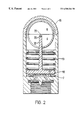
- FIG. 2 is the device of FIG. 1 wherein the diaphragm is in the position taken when the inlet is not mounted on a tyre valve.
- a low tyre pressure warning device 2 having a generally cylindrical casing 9 , is mounted onto a vehicle tyre valve by screw-threading on to the valve housing 1 .
- a nose 6 at the end of a threaded bore 4 in the casing of device 2 depresses the central pin 21 of the valve.
- An O-ring 5 ensures a sealed contact between the device and the valve housing 1 .
- Depressing pin 21 allows pressurised air from the tyre to enter, via inclined ports 3 , the space between the nose 6 and a flexible impermeable diaphragm 7 sealed to the casing 9 .
- the flexible diaphragm 7 spans the inlet and is held in position by a flange 11 on the inner wall of casing 9 . It has a weekened region 18 which will rupture if the pressure in the inlet exceeds that in chamber 8 by more than a predetermined amount.
- a chamber 8 above the diaphragm 7 as shown in the drawings is pressurised and is completely permanently hermetically sealed during manufacture of the device.
- This chamber 8 contains a piston 10 urged by a compression spring 13 towards diaphragm 7 .
- Spring 13 seats on an annular bead 24 in casing 9 .
- a piston rod 12 extends upwardly and is pivoted to a shaft 20 not quite running through the centre of a dual colour ball 14 .
- Ball 14 has on its exterior two small pins defining an axis of rotation 22 , and which are seated in two corresponding formations in the inner wall of casing 9 , so mounting ball 14 rotatably about axis 22 within the casing.
- the ball 14 is visible from the exterior of the device through a transparent lens region 16 of the casing 9 .
- One half is denoted G and is green in colour, the other half, denoted R, being red.
- Rod 12 passes through an arcuate slot in the ball.
- Piston 10 has a perforation bore 17 to ensure that the pressure is equal on each side of the piston.
- the chamber 8 is hermetically sealed during manufacture at a pressure higher than atmospheric but slightly lower than the optimal pressure of the tyre to which the device is to be secured. Therefore, when the tyre pressure is optimum, the higher pressure behind the diaphragm 7 causes it to flex to the position shown in FIG 1 . This movement of the diaphragm, when the device is threaded on to the tyre valve, causes the piston 10 and rod 12 to rise to the position as shown in FIG. 1 and accordingly to rotate the ball 14 so that its green half G is visible through the transparent lens 16 . This provides a clear visual signal which indicates that the pressure in the tyre is sufficiently above the pressure in chamber 8 to overcome the force exerted by spring 13 .
- the ball may bear further colours in order to indicate an intermediate stage between the fully flexed position and fully flattened position of the diaphragm.
- the device of the invention enables the easy detection of a slow puncture, or the like, in a vehicle tyre before it would usually be perceived from observation of the tyre alone, especially with modern “low-profile” tyres.
- the device may easily be produced in a range of “changeover” pressures to match the range of recommended tyre pressures across a wide range of motor vehicles. If desired, two sets of such devices may be provided as standard, one for use when the vehicle is unladen or only lightly loaded, the other for use when the vehicle is laden where slightly higher tyre pressures are often recommended.
- the device of the invention if it is itself subject to failure, e.g. by rupture of diaphragm 7 , immediately indicates such failure to the user; when, after pressurising the tyre to the correct pressure, the device is fitted on to the tyre valve stem, the chamber 8 pressure rises to equal the tyre pressure but, because of spring 13 , the mechanical linkage does not move, so the tyre still appears under-pressurised. Failure of the ball to turn when the device is fitted back on is immediately apparent.
- the substantial pressure differential will rupture diaphragm 7 at region 18 which thus acts as a bursting diaphragm. It will also rupture if the pressure in the inlet exceeds the pressure in the chamber 8 by more than a given threshold e.g. if the pressure in the tyre is greater than twice the pressure in the chamber 8 .
- the device will thus fail if the tyre onto which it is screwed is subject to gross over-pressure, thus giving a very positive indication to the user, when the device is screwed onto the valve stem, that something is seriously wrong.
- loss of pressure in chamber 8 can cause the stem 12 to buckle and e.g. release something in the chamber which will cause the window to adopt a different appearance.
Landscapes
- Engineering & Computer Science (AREA)
- Mechanical Engineering (AREA)
- Measuring Fluid Pressure (AREA)
- Indication Of The Valve Opening Or Closing Status (AREA)
- Diaphragms For Electromechanical Transducers (AREA)
Applications Claiming Priority (1)
| Application Number | Priority Date | Filing Date | Title |
|---|---|---|---|
| PCT/GB1996/001086 WO1997042044A1 (en) | 1996-05-07 | 1996-05-07 | Pressure indicating devices |
Publications (1)
| Publication Number | Publication Date |
|---|---|
| US6588264B1 true US6588264B1 (en) | 2003-07-08 |
Family
ID=10787255
Family Applications (1)
| Application Number | Title | Priority Date | Filing Date |
|---|---|---|---|
| US09/180,306 Expired - Fee Related US6588264B1 (en) | 1996-05-07 | 1996-05-07 | Pressure indicating devices |
Country Status (8)
| Country | Link |
|---|---|
| US (1) | US6588264B1 (de) |
| EP (1) | EP0897336B1 (de) |
| AT (1) | ATE210024T1 (de) |
| AU (1) | AU713315B2 (de) |
| DE (1) | DE69617747T2 (de) |
| DK (1) | DK0897336T3 (de) |
| ES (1) | ES2169238T3 (de) |
| WO (1) | WO1997042044A1 (de) |
Cited By (12)
| Publication number | Priority date | Publication date | Assignee | Title |
|---|---|---|---|---|
| US20030209065A1 (en) * | 2002-05-07 | 2003-11-13 | Siemens Vdo Automotive | Device for fixing a pressure sensor intended to be mounted in a tire |
| US20050072349A1 (en) * | 2003-08-08 | 2005-04-07 | Mike Perlin | Tire pressure indicator |
| US20050223966A1 (en) * | 2004-04-09 | 2005-10-13 | Gary Lemberger | Valve stem pressure poppet |
| US20060059983A1 (en) * | 2004-04-01 | 2006-03-23 | Brandon Maldonado | Tire pressure status indicating device |
| US20080266074A1 (en) * | 2007-04-29 | 2008-10-30 | Changqu Ru | Vehicle Tire Warning System |
| US7607346B1 (en) * | 2006-01-11 | 2009-10-27 | Oboza Andrzej Z | Tire pressure indicator |
| US7667583B2 (en) | 2006-02-13 | 2010-02-23 | Measurement Ltd. | Tire pressure gauge |
| US20100236682A1 (en) * | 2007-10-19 | 2010-09-23 | Norgren Limited | Devices including a mechanochromatic material for indicating pressure |
| US20100319459A1 (en) * | 2009-06-19 | 2010-12-23 | The Swatch Group Research And Development Ltd | Pressure sensor with a diaphragm and depth gauge comprising the same |
| US20110084090A1 (en) * | 2008-04-02 | 2011-04-14 | Macdougall Kenneth L | Angled spout dispensing device |
| US8151127B2 (en) | 2000-07-26 | 2012-04-03 | Bridgestone Americas Tire Operations, Llc | System for conserving battery life in a battery operated device |
| US8266465B2 (en) | 2000-07-26 | 2012-09-11 | Bridgestone Americas Tire Operation, LLC | System for conserving battery life in a battery operated device |
Families Citing this family (2)
| Publication number | Priority date | Publication date | Assignee | Title |
|---|---|---|---|---|
| EP1526006A1 (de) * | 2002-12-12 | 2005-04-27 | Giovanni Barbanti | System für das Festlegen der Ansprechschwelle einer Vorrichtung zur Überwachung des Zustandes der radialen Deformation eines Luftreifens |
| EP2720022B1 (de) * | 2012-10-12 | 2018-03-07 | Magna Steyr Fahrzeugtechnik AG & Co KG | Druckanzeiger für Hochdruckspeicheranlagen |
Citations (11)
| Publication number | Priority date | Publication date | Assignee | Title |
|---|---|---|---|---|
| US3697944A (en) * | 1968-12-13 | 1972-10-10 | Jisaku Murano | Vehicle tire pressure indicating and signalling device |
| US4366708A (en) * | 1980-02-07 | 1983-01-04 | Hisanori Warihashi | Pressure checker for pneumatic tire |
| US4384543A (en) * | 1981-04-29 | 1983-05-24 | Wong Jacob Y | Combined underinflation indicator and relief valve |
| US4465013A (en) * | 1981-01-26 | 1984-08-14 | Allied Oil & Supply, Inc. | Tire monitor |
| US4476803A (en) * | 1983-06-03 | 1984-10-16 | Dual Dynamics, Inc. | Apparatus for indicating tire pressure |
| US4606391A (en) * | 1983-10-28 | 1986-08-19 | Rainer Achterholt | Valve cap with pressure drop indication for pneumatic tires |
| US4819686A (en) * | 1985-12-30 | 1989-04-11 | Rainer Achterholt | Pressure drop indicating valve cap for pneumatic tires |
| US5557256A (en) * | 1993-04-30 | 1996-09-17 | Auto-Zubehor-Innovationen Gasellschaft mbH | Tire pressure loss indicating device |
| US5774048A (en) * | 1993-02-08 | 1998-06-30 | Alpha-Beta Electronics Ag | Valve having means for generating a wireless transmittable indicating signal in case of a pressure drop within vehicle tires |
| US5929330A (en) * | 1997-11-14 | 1999-07-27 | Ford; Robert P. | Visual tire cap pressure indicator |
| US6006600A (en) * | 1997-07-21 | 1999-12-28 | Cheng; Li-Hua | Pressure alarm device |
Family Cites Families (6)
| Publication number | Priority date | Publication date | Assignee | Title |
|---|---|---|---|---|
| US2329039A (en) * | 1942-08-21 | 1943-09-07 | Ivy D Fenwick | Tire air pressure gauge |
| US2689481A (en) * | 1952-04-24 | 1954-09-21 | Gerald M Quiat | Tire pressure indicator |
| US3236097A (en) * | 1963-05-17 | 1966-02-22 | Lattimore & Tessmer Inc | Air pressure gage |
| US3693691A (en) * | 1970-11-23 | 1972-09-26 | Ametek Inc | Pressure relief device |
| US4248080A (en) * | 1979-11-19 | 1981-02-03 | Htl Industries, Inc. | Wheel-mounting tire pressure gage with failsafe features |
| US5027740A (en) * | 1990-01-19 | 1991-07-02 | Robert Kramer | Valve cap pressure drop indicator |
-
1996
- 1996-05-07 WO PCT/GB1996/001086 patent/WO1997042044A1/en not_active Ceased
- 1996-05-07 US US09/180,306 patent/US6588264B1/en not_active Expired - Fee Related
- 1996-05-07 AU AU55103/96A patent/AU713315B2/en not_active Ceased
- 1996-05-07 DE DE69617747T patent/DE69617747T2/de not_active Expired - Lifetime
- 1996-05-07 AT AT96912166T patent/ATE210024T1/de not_active IP Right Cessation
- 1996-05-07 ES ES96912166T patent/ES2169238T3/es not_active Expired - Lifetime
- 1996-05-07 EP EP96912166A patent/EP0897336B1/de not_active Expired - Lifetime
- 1996-05-07 DK DK96912166T patent/DK0897336T3/da active
Patent Citations (11)
| Publication number | Priority date | Publication date | Assignee | Title |
|---|---|---|---|---|
| US3697944A (en) * | 1968-12-13 | 1972-10-10 | Jisaku Murano | Vehicle tire pressure indicating and signalling device |
| US4366708A (en) * | 1980-02-07 | 1983-01-04 | Hisanori Warihashi | Pressure checker for pneumatic tire |
| US4465013A (en) * | 1981-01-26 | 1984-08-14 | Allied Oil & Supply, Inc. | Tire monitor |
| US4384543A (en) * | 1981-04-29 | 1983-05-24 | Wong Jacob Y | Combined underinflation indicator and relief valve |
| US4476803A (en) * | 1983-06-03 | 1984-10-16 | Dual Dynamics, Inc. | Apparatus for indicating tire pressure |
| US4606391A (en) * | 1983-10-28 | 1986-08-19 | Rainer Achterholt | Valve cap with pressure drop indication for pneumatic tires |
| US4819686A (en) * | 1985-12-30 | 1989-04-11 | Rainer Achterholt | Pressure drop indicating valve cap for pneumatic tires |
| US5774048A (en) * | 1993-02-08 | 1998-06-30 | Alpha-Beta Electronics Ag | Valve having means for generating a wireless transmittable indicating signal in case of a pressure drop within vehicle tires |
| US5557256A (en) * | 1993-04-30 | 1996-09-17 | Auto-Zubehor-Innovationen Gasellschaft mbH | Tire pressure loss indicating device |
| US6006600A (en) * | 1997-07-21 | 1999-12-28 | Cheng; Li-Hua | Pressure alarm device |
| US5929330A (en) * | 1997-11-14 | 1999-07-27 | Ford; Robert P. | Visual tire cap pressure indicator |
Cited By (19)
| Publication number | Priority date | Publication date | Assignee | Title |
|---|---|---|---|---|
| US8151127B2 (en) | 2000-07-26 | 2012-04-03 | Bridgestone Americas Tire Operations, Llc | System for conserving battery life in a battery operated device |
| US8266465B2 (en) | 2000-07-26 | 2012-09-11 | Bridgestone Americas Tire Operation, LLC | System for conserving battery life in a battery operated device |
| US6851308B2 (en) * | 2002-05-07 | 2005-02-08 | Siemens Vdo Automotive | Device for fixing a pressure sensor intended to be mounted in a tire |
| US20030209065A1 (en) * | 2002-05-07 | 2003-11-13 | Siemens Vdo Automotive | Device for fixing a pressure sensor intended to be mounted in a tire |
| US20050072349A1 (en) * | 2003-08-08 | 2005-04-07 | Mike Perlin | Tire pressure indicator |
| US20060059983A1 (en) * | 2004-04-01 | 2006-03-23 | Brandon Maldonado | Tire pressure status indicating device |
| US7251994B2 (en) * | 2004-04-01 | 2007-08-07 | Brandon Maldonado | Tire pressure status indicating device |
| US20050223966A1 (en) * | 2004-04-09 | 2005-10-13 | Gary Lemberger | Valve stem pressure poppet |
| US7013833B2 (en) * | 2004-04-09 | 2006-03-21 | Gary Lemberger | Valve stem pressure poppet |
| US7607346B1 (en) * | 2006-01-11 | 2009-10-27 | Oboza Andrzej Z | Tire pressure indicator |
| US7667583B2 (en) | 2006-02-13 | 2010-02-23 | Measurement Ltd. | Tire pressure gauge |
| US7817024B2 (en) * | 2007-04-29 | 2010-10-19 | Changqu Ru | Vehicle tire warning system |
| US20080266074A1 (en) * | 2007-04-29 | 2008-10-30 | Changqu Ru | Vehicle Tire Warning System |
| US20100236682A1 (en) * | 2007-10-19 | 2010-09-23 | Norgren Limited | Devices including a mechanochromatic material for indicating pressure |
| US8511155B2 (en) | 2007-10-19 | 2013-08-20 | Norgren Limited | Devices including a mechanochromatic material for indicating pressure |
| US20110084090A1 (en) * | 2008-04-02 | 2011-04-14 | Macdougall Kenneth L | Angled spout dispensing device |
| US8517216B2 (en) * | 2008-04-02 | 2013-08-27 | Kenneth L. MacDougall | Angled spout dispensing device |
| US20100319459A1 (en) * | 2009-06-19 | 2010-12-23 | The Swatch Group Research And Development Ltd | Pressure sensor with a diaphragm and depth gauge comprising the same |
| US8171799B2 (en) * | 2009-06-19 | 2012-05-08 | The Swatch Group Research And Development Ltd. | Pressure sensor with a diaphragm and depth gauge comprising the same |
Also Published As
| Publication number | Publication date |
|---|---|
| DK0897336T3 (da) | 2002-03-11 |
| DE69617747D1 (de) | 2002-01-17 |
| ATE210024T1 (de) | 2001-12-15 |
| AU5510396A (en) | 1997-11-26 |
| DE69617747T2 (de) | 2002-08-08 |
| AU713315B2 (en) | 1999-11-25 |
| EP0897336A1 (de) | 1999-02-24 |
| EP0897336B1 (de) | 2001-12-05 |
| WO1997042044A1 (en) | 1997-11-13 |
| ES2169238T3 (es) | 2002-07-01 |
Similar Documents
| Publication | Publication Date | Title |
|---|---|---|
| US6588264B1 (en) | Pressure indicating devices | |
| US4136560A (en) | Pressure gauge | |
| US4051803A (en) | Air leakage indicator device for a spare tire | |
| US5365967A (en) | Safety tire valve | |
| US5979232A (en) | Tire pressure indicator carried aboard a wheel | |
| US3906988A (en) | Combined valve and pressure indicator for pneumatic tires | |
| US4512278A (en) | Vehicle tire deflation signalling system | |
| US4248080A (en) | Wheel-mounting tire pressure gage with failsafe features | |
| US20040025581A1 (en) | Method and apparatus for monitoring tire pressure with a color indicator | |
| EP0721403B1 (de) | Reifenventil mit Druckanzeige | |
| WO1986001465A1 (en) | Inflation pressure indicator for vehicle tyres | |
| US3910223A (en) | Inflation and pressure change indication device | |
| US6595046B2 (en) | Temperature and pressure compensating indicator | |
| US4244214A (en) | Visual tire valve | |
| US6055925A (en) | Air gauge wheel | |
| CN1074729C (zh) | 压力指示装置 | |
| CA1096761A (en) | Pressure gauge | |
| US5101754A (en) | Device for surveillance of a pressure in a vehicle tire | |
| US20010023613A1 (en) | Pressure gauge for vehicle tires | |
| US6418786B1 (en) | Aircheck safety valve | |
| GB2294765A (en) | Pressure indicating devices | |
| CA1170922A (en) | Vehicle tire deflation signalling system | |
| US3937077A (en) | Tire pressure indicators and methods of making and using the same | |
| US4729337A (en) | Air pressure indicator | |
| US20020157707A1 (en) | Pressure cutoff valve |
Legal Events
| Date | Code | Title | Description |
|---|---|---|---|
| AS | Assignment |
Owner name: INNOVATIVE ENTERPRISES LIMITED, GIBRALTAR Free format text: ASSIGNMENT OF ASSIGNORS INTEREST;ASSIGNOR:JOHNSON, RICHARD CHRISTOPHER HOIDAS;REEL/FRAME:013817/0955 Effective date: 19981125 |
|
| FPAY | Fee payment |
Year of fee payment: 4 |
|
| FEPP | Fee payment procedure |
Free format text: PAYOR NUMBER ASSIGNED (ORIGINAL EVENT CODE: ASPN); ENTITY STATUS OF PATENT OWNER: SMALL ENTITY |
|
| FPAY | Fee payment |
Year of fee payment: 8 |
|
| REMI | Maintenance fee reminder mailed | ||
| LAPS | Lapse for failure to pay maintenance fees | ||
| STCH | Information on status: patent discontinuation |
Free format text: PATENT EXPIRED DUE TO NONPAYMENT OF MAINTENANCE FEES UNDER 37 CFR 1.362 |
|
| FP | Lapsed due to failure to pay maintenance fee |
Effective date: 20150708 |