US6655152B2 - Fuel control system for multiple burners - Google Patents
Fuel control system for multiple burners Download PDFInfo
- Publication number
- US6655152B2 US6655152B2 US09/962,867 US96286701A US6655152B2 US 6655152 B2 US6655152 B2 US 6655152B2 US 96286701 A US96286701 A US 96286701A US 6655152 B2 US6655152 B2 US 6655152B2
- Authority
- US
- United States
- Prior art keywords
- fuel
- flow
- burners
- flow path
- control system
- Prior art date
- Legal status (The legal status is an assumption and is not a legal conclusion. Google has not performed a legal analysis and makes no representation as to the accuracy of the status listed.)
- Expired - Lifetime, expires
Links
Images
Classifications
-
- F—MECHANICAL ENGINEERING; LIGHTING; HEATING; WEAPONS; BLASTING
- F02—COMBUSTION ENGINES; HOT-GAS OR COMBUSTION-PRODUCT ENGINE PLANTS
- F02C—GAS-TURBINE PLANTS; AIR INTAKES FOR JET-PROPULSION PLANTS; CONTROLLING FUEL SUPPLY IN AIR-BREATHING JET-PROPULSION PLANTS
- F02C7/00—Features, components parts, details or accessories, not provided for in, or of interest apart form groups F02C1/00 - F02C6/00; Air intakes for jet-propulsion plants
- F02C7/22—Fuel supply systems
- F02C7/228—Dividing fuel between various burners
-
- F—MECHANICAL ENGINEERING; LIGHTING; HEATING; WEAPONS; BLASTING
- F02—COMBUSTION ENGINES; HOT-GAS OR COMBUSTION-PRODUCT ENGINE PLANTS
- F02C—GAS-TURBINE PLANTS; AIR INTAKES FOR JET-PROPULSION PLANTS; CONTROLLING FUEL SUPPLY IN AIR-BREATHING JET-PROPULSION PLANTS
- F02C7/00—Features, components parts, details or accessories, not provided for in, or of interest apart form groups F02C1/00 - F02C6/00; Air intakes for jet-propulsion plants
- F02C7/22—Fuel supply systems
- F02C7/236—Fuel delivery systems comprising two or more pumps
Definitions
- This invention relates to a control system for controlling the fuel supply to a combustion engine having two or more sets of burners.
- the arrangement of the burners commonly includes a set of pilot burners, which are on at all times when the engine is running, a set of idling burners, providing a steady low speed operation when the engine is at idle, and one or more sets of main burners, which are fired in stages as thrust demand increases.
- the control system for controlling the supply of fuel to the burners should have the ability to maintain the rate of fuel flow to each set of burners, even when the flow to other sets is changing. Problems can arise with single pump control systems as a reduction in flow can occur in the fuel supply to the pilot and idling burners when a set of main burners is switched on.
- a control system for use in controlling fuel supply to at least two sets of burners of an engine, the control system comprising two or more fuel pumps, each of the pumps being driven, in use, by a respective variable-speed motor, and control means for controlling the speed of the motors so as to regulate the rate of flow of fuel to each of the burners.
- each of the fuel pumps is driven by means of a variable-speed electric motor.
- control system may comprise two pumps, each of the pumps having an inlet and an outlet,
- a first fuel flow path through which fuel flows, in use, from the outlet of a first one of the pumps to a set of pilot burners and to a set of idling burners, and
- the set of idling burners and each set of further burners each preferably having, associated therewith, respective staging valve arrangements.
- the staging valve arrangements may be electrically operated valves. Alternatively, pressure operated check valves may be used.
- the control system may further comprise means for controlling operation of the staging valve arrangements.
- the set of further burners comprises a first set of main burners and a second set of main burners.
- the control means may take the form of an electronic controller associated with the aircraft engine.
- the flow of fuel through the pumps may be rapidly increased to a higher level for a short period of time (i.e. “spiked”), in order to substantially maintain the rate of flow of fuel to one or more sets of burners when another or others of the sets of burners are switched on (i.e. during priming of the newly switched on burners).
- the control algorithms are simpler if each fuel flow path is supplied with fuel from a separate electrically driven pump.
- the first fuel flow path may be provided with a first flow sensing valve for monitoring the rate of fuel flow through the first fuel flow path, whereby the first flow sensing valve provides a first output signal indicative of the rate of flow of fuel through the first fuel flow path, the control means receiving the first output signal such that the speed of at least one of the motors is controlled in response to the first output signal.
- the further fuel flow path may be provided with a further flow sensing valve for monitoring the rate of fuel flow through the further fuel flow path, whereby the further flow sensing valve provides a further output signal indicative of the rate of flow of fuel through the further fuel flow path, the control means receiving the further output signal such that the speed of at least one of the motors is controlled in response to the further output signal.
- At least one of the first or further flow sensing valves may be provided with a position sensor for monitoring the position of the associated flow sensing valve, the position sensor providing an output signal indicative of the rate of flow of fuel through the respective fuel flow path.
- a linear variable differential transducer may be used as the position sensor.
- the further fuel flow path may be provided with a split valve arrangement for dividing the fuel flow into first and second staging fuel flow paths.
- fuel flows through the split valve arrangement into the first staging fuel flow path to a first set of main burners and into the second staging fuel flow path to a second set of main burners, the proportion of the total flow of fuel into the split valve that flows to the first set of main burners being controlled by controlling the position of the split valve arrangement.
- Each staging fuel flow path may be provided with a flow sensing valve for monitoring the rate of fuel flow through the respective staging fuel flow path, whereby the flow sensing valve associated with each staging fuel flow path provides an output signal indicative of the rate of flow of fuel through the associated staging fuel flow path.
- the fuel flow path delivering fuel to the set of pilot burners may be provided with a pressure raising shut-off valve (PRSOV), which serves to maintain a fuel pressure within the system above a predetermined value and prevents the flow of fuel to the set of pilot burners if the fuel pressure falls below a predetermined value.
- PRSOV pressure raising shut-off valve
- the outlets of the pumps may be connected to each other to form a common supply for each set of burners.
- the common supply may deliver fuel to first, second and third fuel flow paths associated with the first, second and third sets of burners respectively.
- Each of the first, second and third flow paths may be provided with a flow regulating valve and a flow sensing valve, the control means including a means of controlling the flow regulating valves in response to an output signal provided by the respective flow sensing valve.
- Each flow regulating valve may include an inlet port and an outlet port, the flow regulating valve being movable to an open position in which fuel at high pressure is able to flow through the associated fuel flow path to the associated set of burners.
- Each flow regulating valve may further include a low pressure inlet port and a low pressure outlet port, the flow regulating valve being movable to a closed position in which high pressure fuel flow is prevented but fuel at low pressure is able to flow through the low pressure inlet port, through the low pressure outlet port and into the associated fuel flow path to permit priming of the associated set of fuel manifolds with low pressure fuel.
- Each main manifold may have an associated air vent valve arrangement, the air vent valve arrangement being opened during priming of the respective main manifold in order that air and/or other gases in the respective fuel flow path is able to escape through the air vent valve arrangement. Any low pressure fuel which may escape through the air vent valve arrangement flows to a low pressure drain.
- the air vent valve arrangement is closed, the respective flow regulating valve remains closed and flow of the low pressure fuel to the main burners is prevented by the staging valves which remain closed.
- the PRSOV associated with the pilot burners may be used to purge the manifolds and fuel supply paths between the flow regulating valves and the associated burners on shut down by permitting fuel in the fuel flow path through which fuel flows to the associated set of burners to flow through the PRSOV to the low pressure drain after the burners have been switched off.
- a method of controlling fuel supply to at least two sets of burners comprises the steps of providing two or more fuel pumps, driving each of the fuel pumps by a respective variable-speed motor, and controlling the speed of the motors so as to regulate the rate of flow of fuel to each of the sets of burners.
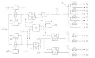
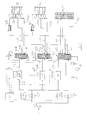
- FIG. 1 is a schematic block diagram of a staged combustion gas turbine engine control system using two electrically driven pumps in accordance with an embodiment of the present invention
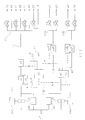
- FIG. 2 is a schematic block diagram of a staged combustion gas turbine engine control system using two electrically driven pumps in accordance with an alternative embodiment of the present invention, with the pump outlets connected to each other to form a common supply;
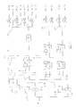
- FIG. 3 is a schematic block diagram of a staged combustion gas turbine engine control system using four electrically driven pumps in accordance with a further alternative embodiment of the present invention.
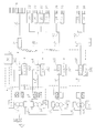
- FIG. 4 is a schematic block diagram of a staged combustion gas turbine engine control system in accordance with a further alternative embodiment of the present invention, in which the sets of burners may be primed and purged.
- fuel at low pressure, LP is supplied to the inlets of two positive displacement pumps 12 a , 12 b , which are driven by respective variable speed electric motors 14 a , 14 b , each of the pumps having an associated relief valve 9 a , 9 b .
- a first one of the pumps 12 a delivers fuel at a high pressure to the inlet manifold 16 of a set of pilot burners 18 and a set of idling burners 22 through a fuel flow path 13 , the fuel flow path 13 being provided with a flow sensing valve 36 and a pressure raising shut-off valve 34 .
- the idling burners have, associated therewith, staging valves 20 which are operable between an open position, in which fuel in the flow path is delivered to the idling burners 22 , and a closed position in which such fuel delivery is prevented.
- the other fuel pump 12 b delivers fuel at a high pressure to the inlet manifolds 17 a , 17 b of further sets of main burners 26 , 28 , each having an associated staging valve arrangement 24 , 25 respectively.
- the fuel supply to the sets of main burners 26 , 28 is divided by means of a split valve arrangement 40 , the position of which is controlled by means of a motor 42 , the split valve arrangement 40 being arranged such that the common supply of fuel from the pump 12 b is delivered to first and second flow paths 43 a , 43 b , the first flow path 43 a delivering fuel to the main burners 26 and the second flow path 43 b delivering fuel to the main burners 28 .
- Each of the flow paths 43 a , 43 b is provided with a flow sensing valve 44 a , 44 b for monitoring the rate of fuel flow through the respective flow path 43 a , 43 b.
- each of the flow sensing valves 36 , 44 a , 44 b is provided with a linear variable differential transducer (LVDT) 38 , 46 a , 46 b respectively for monitoring the position of a valve member forming part of the respective flow sensing valve, each of the LVDTs 38 , 46 a , 46 b providing an output signal which is indicative of the rate of flow of fuel through the respective flow path.
- LVDT linear variable differential transducer
- the output signals generated by the LVDTs 38 , 46 a , 46 b are provided to a control unit 30 , conveniently a computer or an electronic control means with a computer interface, which generates control signals 27 a , 27 b for controlling the speed of the pump motors 14 a , 14 b respectively in response to the LVDT output signals.
- the control unit 30 may also receive other demand signals 32 from the engine, as would be familiar to a person skilled in the art.
- the control unit 30 is also arranged to provide control signals 33 to control the opening and closing of the staging valves 20 , 24 , 25 at the desired stage in the engine operating procedure.
- electrically operated staging valves 20 , 24 , 25 are described, it is also possible to use pressure operated check valves.
- fuel is delivered by the pump 12 a to the set of pilot burners 18 which are ignited on start-up.
- the control unit 30 generates a control signal 33 to cause the staging valves 20 associated with the set of idling burners 22 to open so as to permit fuel to flow thereto, the set of pilot burners 18 causing ignition of the idling burners 22 .
- the LVDT associated with the flow sensing valve 36 provides an output signal to the control unit 30 which is indicative of the rate of fuel flow through the flow path 13 .
- the control unit 30 When the staging valves 20 are opened, and in response to the measured fuel flow rate, the control unit 30 provides a control signal 27 a to the electric motor 14 a , whereby the speed of the electric motor 14 a is varied so as to ensure the flow of fuel to the pilot burners 18 and idling burners 22 is maintained at a predetermined required rate.
- the control unit 30 increases the speed of the second pump 12 b and generates a further control signal 33 to open at least one of the staging valves 24 , 25 associated with the sets of main burners 26 , 28 respectively, thereby permitting fuel to flow from the second pump 12 b , through the flow paths 43 a , 43 b to the sets of main burners 26 , 28 , the main burners 26 , 28 being ignited by the pilot burners 18 .
- the LVDTs 46 a , 46 b associated with the flow sensing valves 44 a , 44 b respectively monitor the fuel flow rates through the flow paths 43 a , 43 b and provide output signals, indicative of the rates of fuel flow to each of the sets of main burners 26 , 28 , to the control unit 30 .
- the control unit 30 provides an output signal to the motor 42 to control the position of the split valve arrangement 40 and provides an output signal 27 b to control the speed of the electric motor 14 b associated with pump 12 b so as to ensure the flow of fuel to both the sets of main burners 26 , 28 is maintained at a substantially constant rate.
- the invention provides the advantage that the fuel flow rates to all sets of burners may be substantially maintained during operation of the engine, including periods during which other sets of burners are being primed after being selected for switching on.
- a further advantage of the present invention is that the use of electrically driven pumps removes the requirement for a spillback loop, as used on mechanically driven pumps, and reduces the heat rejection of the system.
- the invention also enables electrically driven fuel pumps having different operating parameters to be selected to suit the range of fuel flow rates required by different sets of burners. Furthermore, in order to control fuel flow rates in two or more fuel flow paths, it is computationally easier to program the control unit 30 so as to control two electrically driven pumps than to control a single pump to achieve the same purpose.
- FIG. 2 An alternative embodiment of the invention is shown in FIG. 2, in which fuel at low pressure LP is supplied to the inlets of two positive displacement pumps 12 a , 12 b , each of which is driven by an associated variable speed electric motor 14 a , 14 b respectively.
- the outlets of the pumps 12 a , 12 b are coupled together to form a common supply path 15 which delivers fuel to the manifold 16 of a set of pilot burners 18 and staging valves 20 associated with idling burners 22 through a first flow path 19 a .
- the flow path 19 a is provided with a flow sensing valve 36 having an associated LVDT 38 and a PRSOV 34 .
- the LVDT 38 provides an output signal to the control unit 30 which provides an indication of the rate of flow of fuel through the flow path 19 a.
- the common supply path 15 also delivers fuel to first and second additional flow paths 19 b , 19 c which deliver fuel to the manifolds 17 a , 17 b of further sets of main burners 26 , 28 respectively provided with staging valves 24 , 25 respectively.
- the additional flow paths 19 b , 19 c are also provided with flow sensing valves 44 a , 44 b , each valve 44 a , 44 b having an associated LVDT 46 a , 46 b respectively which provides an output signal, indicative of the rates of fuel flow through the associated flow path 19 b , 19 c , to the control unit 30 .
- Each additional flow path 19 b , 19 c is further provided with a flow regulating valve 52 a , 52 b actuated by an associated motor arrangement 54 a , 54 b .
- the control unit 30 provides signals 33 to control the opening and closing of the staging valves 20 , 24 , 25 and also provides signals to control the motor arrangements, 54 a , 54 b and the electric motors 14 a , 14 b in response to signals 32 from the engine and from the LVDTs 38 , 46 a , 46 b.
- the system in FIG. 2 operates in a similar manner to that described previously, except that the flow rate of fuel in each of the flow paths 19 a , 19 b , 19 c is controlled by providing signals from the control unit 30 , in response to the output signals from the LVDTs 38 , 46 a , 46 b , to the motor arrangements 54 a , 54 b for the flow regulating valves 52 a , 52 b as well as to the electric motors 14 a , 14 b associated with the pumps 12 a , 12 b .
- the total fuel flow entering the common supply path 15 is controlled by providing signals 27 a , 27 b to vary the speed of the electric motors 14 a , 14 b in response to the output signals from the LVDTs 38 , 46 a , 46 b.
- the embodiment of the invention in FIG. 2 provides the further advantage that, as the pumps 12 a , 12 b are arranged in parallel, fuel supply to the engine can be substantially maintained, even if one of the pumps 12 a , 12 b should fail. It will be appreciated that further pumps, and further flow paths, may be included in the system in FIG. 2 to control fuel supply to further sets of burners, if required.
- FIG. 3 Another alternative embodiment of the invention is shown in FIG. 3, in which fuel at low pressure, LP, is supplied to the inlets of four positive displacement pumps 12 a , 12 b , 12 c , 12 d , driven by associated variable speed electric motors 14 a , 14 b , 14 c , 14 d , respectively.
- the pilot burners 18 are supplied with fuel through a first flow path 13 a from pump 12 a and the idling burners 22 are supplied with fuel through a second flow path 13 b from pump 12 b .
- Two sets of further, main burners 26 , 28 are each supplied with fuel through associated third and fourth flow paths 13 c , 13 d from associated pumps 12 c , 12 d respectively.
- the operation is similar to that described previously with reference to FIGS. 1 and 2, the motors 14 a , 14 b , 14 c , 14 d being controlled by signals from the control unit 30 , which are generated in response to the output signals from the LVDTs 38 a , 38 b , 38 c , 38 d associated with the flow sensing valves 36 a , 36 b , 36 c , 36 d such that the fuel flow rate to each set of burners is substantially maintained during engine operation.
- the fuel flow rate to each set of burners can be maintained during periods in which the fuel supply to other sets of burners is initiated, for example upon opening of the associated staging valves.
- each set of burners can be controlled independently by varying the speed of the electric motor driving the associated pump, each of which supplies fuel to only one set of burners.
- the control system includes a valve arrangement 60 which takes the form of a PRSOV which is also used to purge the manifolds at shut down.
- the PRSOV 60 has an inlet port 61 in communication with the fuel supply flow path 19 a and an outlet port 62 in communication with a flow path 69 , the flow path 69 being in communication with the inlet manifold 16 of the pilot and idling burners 18 , 22 .
- a further port 63 of the PRSOV 60 is in communication with a low pressure drain 81 , the further port 63 also being in communication with a common flow path 82 which is provided with first and second air vent valve arrangements 80 a , 80 b associated with the sets of main burners 26 , 28 respectively.
- the flow regulating valve 52 a is movable between a position in which high pressure fuel is able to flow from the flow path 19 b , through the valve 52 a and into a flow path 77 a in communication with the inlet manifold 17 a of the main burners 26 and a position in which low pressure fuel flowing through PRSOV 60 is able to flow through the flow path 75 , into the priming flow path 76 a .
- the flow regulating valve 52 b is operable in a similar manner so as to permit either high pressure fuel from the flow path 19 c to flow through the valve 52 b to a flow path 77 b in communication with the inlet manifold 17 b of the burners 28 or to permit low pressure fuel flowing through the PRSOV 60 to flow through the flow path 75 , into the priming flow path 76 b.
- the control system shown in FIG. 4 may also be used to prime the flow paths 77 a , 77 b with low pressure fuel prior to ignition of the associated burners and to purge the flow paths 77 a , 77 b , 69 at shut down.
- the PRSOV 60 is moved to a position in which high pressure fuel is able to flow through the inlet port 61 , through the PRSOV 60 and out through the outlet port 62 into the flow path 69 .
- staging valves (not shown in FIG. 4) associated with the idling burners are opened, as described previously, to permit fuel under high pressure to be delivered to the idling burners.
- the main manifolds 17 a , 17 b Prior to their ignition, the main manifolds 17 a , 17 b are primed with low pressure fuel by moving the PRSOV 60 to a position in which low pressure fuel is able to flow through the PRSOV into the flow path 75 .
- the flow regulating valves 52 a , 52 b With the flow regulating valves 52 a , 52 b in their closed positions, low pressure fuel is able to flow from the flow path 75 into the priming flow paths 76 a , 76 b and into the inlet manifolds 17 a , 17 b .
- the air vent valve arrangements 80 a , 80 b are opened, allowing air and/or other gases to escape as the fuel fills the manifolds 17 a , 17 b and, hence, the flow paths 77 a , 77 b . Any fuel escaping through the air vent valve arrangements 80 a , 80 b is returned through flow path 82 to the low pressure drain 81
- the staging valve arrangement 24 associated with the main burners 26 is opened, the air vent valve arrangement 80 a is closed and the valve 52 a is opened so that high pressure fuel is able to flow through the valve 52 a into the flow path 77 a for delivery to the burners 26 . It will be appreciated that, under such circumstances, the delivery of low pressure fuel through the PRSOV 60 to the inlet manifold 17 a of the burners 26 is prevented.
- the main burners 28 Prior to their ignition, the main burners 28 are primed in a similar manner to that described previously for the main burners 26 .
- the staging valves associated therewith are closed and provided the PRSOV 60 is open, the associated flow paths remain filled with low pressure fuel from the low pressure fuel supply 84 .
- Operating the flow regulating valve 52 a to shut off the flow of high pressure fuel to the inlet manifold 17 a enables fuel to flow through the PRSOV 60 from the supply 84 to the manifold 76 a .
- the associated flow paths are filled with low pressure fuel in a similar manner.
- the staging valves associated therewith are closed and the associated flow paths are purged by closing the PRSOV 60 so that the supply of high pressure fuel to the pilot and idling burners is prevented and fuel in the inlet manifold 16 is able to flow through the PRSOV 60 to purge the manifolds 16 , 17 a , 17 b as follows.
- the flow path 68 communicates with the flow path 82 and air is able to flow into the manifolds 17 a , 17 b via the air vent valve arrangements 80 a , 80 b respectively.
- control system of the present invention may be extended to include a greater number of pumps and a greater or lesser number of sets of burners and associated valves, whilst still achieving the aforementioned advantages of the present invention. It will further be appreciated that in any of the embodiments of the invention, the speed of the pump(s) need not be controlled in response to the measured fuel flow rate to the burners but may be controlled in response to other demand signals from the engine. It will further be appreciated that the control system described may be used in conjunction with any type of pump having a variable speed drive arrangement.
Landscapes
- Engineering & Computer Science (AREA)
- Chemical & Material Sciences (AREA)
- Combustion & Propulsion (AREA)
- Mechanical Engineering (AREA)
- General Engineering & Computer Science (AREA)
- Feeding And Controlling Fuel (AREA)
Applications Claiming Priority (3)
| Application Number | Priority Date | Filing Date | Title |
|---|---|---|---|
| GB0023727.1 | 2000-09-27 | ||
| GBGB0023727.1A GB0023727D0 (en) | 2000-09-27 | 2000-09-27 | Control system |
| GB0023727 | 2000-09-27 |
Publications (2)
| Publication Number | Publication Date |
|---|---|
| US20020038540A1 US20020038540A1 (en) | 2002-04-04 |
| US6655152B2 true US6655152B2 (en) | 2003-12-02 |
Family
ID=9900266
Family Applications (1)
| Application Number | Title | Priority Date | Filing Date |
|---|---|---|---|
| US09/962,867 Expired - Lifetime US6655152B2 (en) | 2000-09-27 | 2001-09-25 | Fuel control system for multiple burners |
Country Status (4)
| Country | Link |
|---|---|
| US (1) | US6655152B2 (fr) |
| EP (1) | EP1193379B1 (fr) |
| DE (1) | DE60131126T2 (fr) |
| GB (1) | GB0023727D0 (fr) |
Cited By (17)
| Publication number | Priority date | Publication date | Assignee | Title |
|---|---|---|---|---|
| US20040025492A1 (en) * | 2002-03-15 | 2004-02-12 | Michael Griffiths | Fuel system |
| US20040107701A1 (en) * | 2002-05-31 | 2004-06-10 | Yoshiaki Miyake | System and method for controlling combustion in gas turbine with annular combustor |
| US20070148605A1 (en) * | 2003-03-11 | 2007-06-28 | Lowrie James R | Splitter valve |
| US20070180831A1 (en) * | 2006-02-09 | 2007-08-09 | Siemens Power Generation, Inc. | Fuel flow tuning for a stage of a gas turbine engine |
| US20070245744A1 (en) * | 2006-04-24 | 2007-10-25 | Pratt & Whitney Canada Corp. | Fuel system of gas turbine engines |
| US20070283935A1 (en) * | 2006-05-16 | 2007-12-13 | Toyota Jidosha Kabushiki Kaisha | Fuel pump control apparatus for internal combustion engine |
| US20080260519A1 (en) * | 2007-04-19 | 2008-10-23 | Pratt & Whitney Canada Corp. | Surge detection in a gas turbine engine |
| US20080289314A1 (en) * | 2007-05-22 | 2008-11-27 | David August Snider | Methods and apparatus for operating gas turbine engines |
| US20100043387A1 (en) * | 2007-11-01 | 2010-02-25 | Geoffrey David Myers | Methods and systems for operating gas turbine engines |
| US20100058770A1 (en) * | 2008-09-08 | 2010-03-11 | Siemens Power Generation, Inc. | Method and System for Controlling Fuel to a Dual Stage Nozzle |
| US20110072826A1 (en) * | 2009-09-25 | 2011-03-31 | General Electric Company | Can to can modal decoupling using can-level fuel splits |
| US8499542B2 (en) | 2011-08-17 | 2013-08-06 | Hamilton Sundstrand Corporation | Flow balancing valve |
| US8666632B2 (en) | 2011-04-20 | 2014-03-04 | Hamilton Sundstrand Corporation | Distributed aircraft engine fuel system |
| US20140165580A1 (en) * | 2012-12-18 | 2014-06-19 | General Electric Company | Fuel routing system of a gas turbine engine and method of routing fuel |
| RU2540204C2 (ru) * | 2013-05-23 | 2015-02-10 | Федеральное государственное унитарное предприятие "Центральный институт авиационного моторостроения имени П.И. Баранова" | Электроприводной насос |
| US10087852B2 (en) | 2013-12-30 | 2018-10-02 | Rolls-Royce North American Technologies, Inc. | Fuel flow splitter and gas turbine fuel system health monitoring |
| RU2725919C1 (ru) * | 2019-11-15 | 2020-07-07 | Акционерное общество "Омское машиностроительное конструкторское бюро" | Способ контроля технического состояния насоса топливорегулирующей системы газотурбинного двигателя |
Families Citing this family (24)
| Publication number | Priority date | Publication date | Assignee | Title |
|---|---|---|---|---|
| US6637184B2 (en) * | 2002-01-24 | 2003-10-28 | Siemens Westinghouse Power Corporation | Flow control system for liquid fuel engine having stage-specific control of fuel flow to several groups of nozzles in the engine |
| GB0216043D0 (en) * | 2002-07-11 | 2002-08-21 | Lucas Industries Ltd | Fuel system |
| US7322373B2 (en) * | 2003-08-05 | 2008-01-29 | Honeywell International, Inc. | High accuracy low leakage valve for high pressure applications |
| US6996970B2 (en) * | 2003-09-30 | 2006-02-14 | Honeywell International Inc. | High accuracy fuel metering system for turbine engines |
| US7036302B2 (en) * | 2004-03-15 | 2006-05-02 | General Electric Company | Controlled pressure fuel nozzle system |
| FR2867552B1 (fr) * | 2004-03-15 | 2008-07-11 | Gen Electric | Injecteur de carburant a pression regulee |
| US6955040B1 (en) * | 2004-03-31 | 2005-10-18 | General Electric Company | Controlled pressure fuel nozzle injector |
| US7197879B2 (en) * | 2004-04-29 | 2007-04-03 | Honeywell International, Inc. | Multiple electric fuel metering systems for gas turbine applications |
| GB0700511D0 (en) * | 2007-01-11 | 2007-02-21 | Goodrich Control Sys Ltd | Fuel System |
| US8127548B2 (en) * | 2008-02-21 | 2012-03-06 | Honeywell International Inc. | Hybrid electrical/mechanical turbine engine fuel supply system |
| CH700991A1 (de) * | 2009-05-13 | 2010-11-15 | Alstom Technology Ltd | Verfahren zum betrieb einer gasturbinenanlage mit einer verdichterstation für gasförmigen brennstoff. |
| FR2950863B1 (fr) * | 2009-10-06 | 2012-03-02 | Snecma | Circuit d'alimentation en carburant d'un moteur d'aeronef |
| FR2971548B1 (fr) * | 2011-02-11 | 2015-02-13 | Snecma | Systeme d'alimentation en carburant a moyens de pompage multiples |
| RU2507406C1 (ru) * | 2012-08-14 | 2014-02-20 | Российская Федерация, От Имени Которой Выступает Министерство Промышленности И Торговли Российской Федерации | Система подачи топлива в газотурбинный двигатель с форсажной камерой сгорания |
| RU2507407C1 (ru) * | 2012-08-14 | 2014-02-20 | Российская Федерация, От Имени Которой Выступает Министерство Промышленности И Торговли Российской Федерации | Система подачи топлива в камеру сгорания газотурбинного двигателя |
| EP2853719A1 (fr) * | 2013-09-25 | 2015-04-01 | Alstom Technology Ltd | Turbine à gaz avec injection de carburant étagée |
| JP6286580B2 (ja) * | 2014-03-31 | 2018-02-28 | シーメンス アクティエンゲゼルシャフト | ガスタービン設備のガス供給系のための圧力調整装置 |
| GB201418685D0 (en) * | 2014-10-21 | 2014-12-03 | Rolls Royce Plc | Gas turbine engine fuel system |
| RU2636360C1 (ru) * | 2017-03-16 | 2017-11-22 | Акционерное общество "Научно-производственный центр газотурбостроения "Салют" (АО НПЦ газотурбостроения "Салют") | Система подачи топлива в камеру сгорания авиационного газотурбинного двигателя |
| RU2648479C1 (ru) * | 2017-04-06 | 2018-03-26 | Акционерное общество "Научно-производственный центр газотурбостроения "Салют" (АО НПЦ газотурбостроения "Салют") | Система автоматического управления авиационного газотурбинного двигателя |
| EP3726034B1 (fr) * | 2017-12-14 | 2024-05-01 | Ihi Corporation | Dispositif d'alimentation en carburant |
| EP4023871B1 (fr) * | 2019-08-30 | 2025-08-06 | Kawasaki Jukogyo Kabushiki Kaisha | Moteur à turbine à gaz |
| US20230072590A1 (en) * | 2021-09-08 | 2023-03-09 | Rolls-Royce North American Technologies Inc. | Redundant electrically driven fuel and oil pumping system for gas turbines |
| US20240263589A1 (en) * | 2023-02-03 | 2024-08-08 | Woodward, Inc. | Systems and methods for dual, motor-driven pumping and direct metering |
Citations (5)
| Publication number | Priority date | Publication date | Assignee | Title |
|---|---|---|---|---|
| US4004412A (en) * | 1974-12-20 | 1977-01-25 | Chandler Evans Inc. | Gas turbine engine fuel metering system |
| US4208871A (en) * | 1977-08-29 | 1980-06-24 | The Garrett Corporation | Fuel control system |
| US5118258A (en) * | 1990-09-04 | 1992-06-02 | United Technologies Corporation | Dual pump fuel delivery system |
| WO2001020148A2 (fr) * | 1999-08-20 | 2001-03-22 | Siemens Westinghouse Power Corporation | Systeme et procedes permettant de commander une turbine a gaz faisant intervenir des pompes a combustible liquide a vitesse variable a elements couples |
| US20010054290A1 (en) * | 2000-06-15 | 2001-12-27 | Argo-Tech Corporation | Low-cost general aviation fuel control system |
Family Cites Families (4)
| Publication number | Priority date | Publication date | Assignee | Title |
|---|---|---|---|---|
| BE487119A (fr) * | 1946-04-01 | |||
| GB852290A (en) * | 1957-01-28 | 1960-10-26 | Rolls Royce | Engine liquid fuel supply system |
| GB2282186B (en) * | 1993-09-08 | 1997-09-24 | Rolls Royce Plc | Engine fuel metering system |
| SE521324C2 (sv) * | 1998-05-15 | 2003-10-21 | Abb Ab | Anordning för tillförsel av ett flytande bränsle till ett brännarorgan |
-
2000
- 2000-09-27 GB GBGB0023727.1A patent/GB0023727D0/en not_active Ceased
-
2001
- 2001-09-24 DE DE60131126T patent/DE60131126T2/de not_active Expired - Lifetime
- 2001-09-24 EP EP01308088A patent/EP1193379B1/fr not_active Expired - Lifetime
- 2001-09-25 US US09/962,867 patent/US6655152B2/en not_active Expired - Lifetime
Patent Citations (5)
| Publication number | Priority date | Publication date | Assignee | Title |
|---|---|---|---|---|
| US4004412A (en) * | 1974-12-20 | 1977-01-25 | Chandler Evans Inc. | Gas turbine engine fuel metering system |
| US4208871A (en) * | 1977-08-29 | 1980-06-24 | The Garrett Corporation | Fuel control system |
| US5118258A (en) * | 1990-09-04 | 1992-06-02 | United Technologies Corporation | Dual pump fuel delivery system |
| WO2001020148A2 (fr) * | 1999-08-20 | 2001-03-22 | Siemens Westinghouse Power Corporation | Systeme et procedes permettant de commander une turbine a gaz faisant intervenir des pompes a combustible liquide a vitesse variable a elements couples |
| US20010054290A1 (en) * | 2000-06-15 | 2001-12-27 | Argo-Tech Corporation | Low-cost general aviation fuel control system |
Cited By (33)
| Publication number | Priority date | Publication date | Assignee | Title |
|---|---|---|---|---|
| US20040025492A1 (en) * | 2002-03-15 | 2004-02-12 | Michael Griffiths | Fuel system |
| US6813876B2 (en) * | 2002-03-15 | 2004-11-09 | Goodrich Control Systems Ltd. | Fuel system |
| US20040107701A1 (en) * | 2002-05-31 | 2004-06-10 | Yoshiaki Miyake | System and method for controlling combustion in gas turbine with annular combustor |
| US7024862B2 (en) * | 2002-05-31 | 2006-04-11 | Mitsubishi Heavy Industries, Ltd. | System and method for controlling combustion in gas turbine with annular combustor |
| US20070148605A1 (en) * | 2003-03-11 | 2007-06-28 | Lowrie James R | Splitter valve |
| US20070180831A1 (en) * | 2006-02-09 | 2007-08-09 | Siemens Power Generation, Inc. | Fuel flow tuning for a stage of a gas turbine engine |
| US7805922B2 (en) * | 2006-02-09 | 2010-10-05 | Siemens Energy, Inc. | Fuel flow tuning for a stage of a gas turbine engine |
| US20070245744A1 (en) * | 2006-04-24 | 2007-10-25 | Pratt & Whitney Canada Corp. | Fuel system of gas turbine engines |
| WO2007121553A1 (fr) * | 2006-04-24 | 2007-11-01 | Pratt & Whitney Canada Corp. | Circuit d'alimentation de moteurs a turbine a gaz |
| US9261025B2 (en) | 2006-04-24 | 2016-02-16 | Pratt & Whitney Canada Corp. | Fuel system of gas turbine engines |
| US8844292B2 (en) | 2006-04-24 | 2014-09-30 | Pratt & Whitney Canada Corp. | Fuel system of gas turbine engines |
| US8756937B2 (en) | 2006-04-24 | 2014-06-24 | Pratt & Whitney Canada Corp. | Fuel system of gas turbine engines |
| US7726112B2 (en) | 2006-04-24 | 2010-06-01 | Pratt & Whitney Canada Corp. | Fuel system of gas turbine engines |
| US20100199681A1 (en) * | 2006-04-24 | 2010-08-12 | Pratt & Whitney Canada Corp. | Fuel system of gas turbine engines |
| US20070283935A1 (en) * | 2006-05-16 | 2007-12-13 | Toyota Jidosha Kabushiki Kaisha | Fuel pump control apparatus for internal combustion engine |
| WO2008128326A1 (fr) * | 2007-04-19 | 2008-10-30 | Pratt & Whitney Canada Corp. | Détection de surpression dans une turbine à gaz |
| US7530260B2 (en) | 2007-04-19 | 2009-05-12 | Pratt & Whitney Canada Corp. | Surge detection in a gas turbine engine |
| US20080260519A1 (en) * | 2007-04-19 | 2008-10-23 | Pratt & Whitney Canada Corp. | Surge detection in a gas turbine engine |
| US8429917B2 (en) | 2007-05-22 | 2013-04-30 | General Electric Company | Fuel control method of a can annular combustor array |
| US8459034B2 (en) * | 2007-05-22 | 2013-06-11 | General Electric Company | Methods and apparatus for operating gas turbine engines |
| DE102008023426B4 (de) * | 2007-05-22 | 2024-05-29 | General Electric Technology Gmbh | Verfahren und Vorrichtung für den Betrieb von Gasturbinentriebwerken |
| US20080289314A1 (en) * | 2007-05-22 | 2008-11-27 | David August Snider | Methods and apparatus for operating gas turbine engines |
| US20100043387A1 (en) * | 2007-11-01 | 2010-02-25 | Geoffrey David Myers | Methods and systems for operating gas turbine engines |
| US8122725B2 (en) * | 2007-11-01 | 2012-02-28 | General Electric Company | Methods and systems for operating gas turbine engines |
| US20100058770A1 (en) * | 2008-09-08 | 2010-03-11 | Siemens Power Generation, Inc. | Method and System for Controlling Fuel to a Dual Stage Nozzle |
| US20110072826A1 (en) * | 2009-09-25 | 2011-03-31 | General Electric Company | Can to can modal decoupling using can-level fuel splits |
| US8666632B2 (en) | 2011-04-20 | 2014-03-04 | Hamilton Sundstrand Corporation | Distributed aircraft engine fuel system |
| US8499542B2 (en) | 2011-08-17 | 2013-08-06 | Hamilton Sundstrand Corporation | Flow balancing valve |
| US20140165580A1 (en) * | 2012-12-18 | 2014-06-19 | General Electric Company | Fuel routing system of a gas turbine engine and method of routing fuel |
| US9353691B2 (en) * | 2012-12-18 | 2016-05-31 | General Electric Company | Fuel routing system of a gas turbine engine and method of routing fuel |
| RU2540204C2 (ru) * | 2013-05-23 | 2015-02-10 | Федеральное государственное унитарное предприятие "Центральный институт авиационного моторостроения имени П.И. Баранова" | Электроприводной насос |
| US10087852B2 (en) | 2013-12-30 | 2018-10-02 | Rolls-Royce North American Technologies, Inc. | Fuel flow splitter and gas turbine fuel system health monitoring |
| RU2725919C1 (ru) * | 2019-11-15 | 2020-07-07 | Акционерное общество "Омское машиностроительное конструкторское бюро" | Способ контроля технического состояния насоса топливорегулирующей системы газотурбинного двигателя |
Also Published As
| Publication number | Publication date |
|---|---|
| GB0023727D0 (en) | 2000-11-08 |
| DE60131126D1 (de) | 2007-12-13 |
| EP1193379A2 (fr) | 2002-04-03 |
| EP1193379B1 (fr) | 2007-10-31 |
| EP1193379A3 (fr) | 2005-09-07 |
| US20020038540A1 (en) | 2002-04-04 |
| DE60131126T2 (de) | 2008-08-07 |
Similar Documents
| Publication | Publication Date | Title |
|---|---|---|
| US6655152B2 (en) | Fuel control system for multiple burners | |
| US7845177B2 (en) | Metering demand fuel system | |
| US4305255A (en) | Combined pilot and main burner | |
| EP3061949B1 (fr) | Système de combustion étagée | |
| EP2063087B1 (fr) | Dispositif d'alimentation étagée de carburant | |
| EP1344916B1 (fr) | Système d'alimentation en carburant | |
| EP3211200B1 (fr) | Système de combustion étagée | |
| EP0481620B1 (fr) | Système de commande de combustible pour turbine à gaz | |
| US9470152B2 (en) | Engine fuel control system | |
| EP2138688B1 (fr) | Agencement de contrôle de carburant | |
| US20170306856A1 (en) | Engine fuel control system | |
| WO1988008075A1 (fr) | Systeme de combustion de combustibles gazeux ayant une large plage de valeurs calorifiques pour moteurs a turbine a gaz | |
| US20180163636A1 (en) | Fuel supply system | |
| EP0388046A2 (fr) | Système de commande de combustible d'un moteur à turbine à gaz et soupape de dosage | |
| EP1344917A2 (fr) | Système de régulation d'alimentation en carburant | |
| EP1360439B1 (fr) | Procede et dispositif cedant du carburant a une chambre de combustion | |
| EP0481592A1 (fr) | Système de circulation pour un flux continu de carburant | |
| KR960003682B1 (ko) | 덕트압력 손실보상기능을 갖는 가속제어장치 | |
| US6666014B2 (en) | Two-level pressurization valve controlled by a fuel metering unit | |
| US4411137A (en) | Priming device for burner manifolds of gas turbine engine | |
| US2979889A (en) | Temperature-modified exhaust nozzle scheduling controller for a gas turbine engine | |
| GB2086482A (en) | Priming device for burner manifolds of gas turbine engines | |
| US5076048A (en) | Fuel control system for gas turbine engine | |
| US5179831A (en) | Stored energy system for driving a turbine wheel | |
| RU2781460C1 (ru) | Способ управления газотурбинным двигателем с форсажной камерой сгорания |
Legal Events
| Date | Code | Title | Description |
|---|---|---|---|
| AS | Assignment |
Owner name: LUCAS INDUSTRIES LIMITED, UNITED KINGDOM Free format text: ASSIGNMENT OF ASSIGNORS INTEREST;ASSIGNORS:GRIFFITHS, MICHAEL;SMITH, TREVOR STANLEY;REEL/FRAME:012210/0087 Effective date: 20010920 |
|
| AS | Assignment |
Owner name: GOODRICH CONTROL SYSTEMS LIMITED, ENGLAND Free format text: ASSIGNMENT OF ASSIGNORS INTEREST;ASSIGNOR:LUCAS INDUSTRIES LIMITED;REEL/FRAME:013862/0686 Effective date: 20021001 |
|
| STCF | Information on status: patent grant |
Free format text: PATENTED CASE |
|
| FPAY | Fee payment |
Year of fee payment: 4 |
|
| FPAY | Fee payment |
Year of fee payment: 8 |
|
| FEPP | Fee payment procedure |
Free format text: PAYOR NUMBER ASSIGNED (ORIGINAL EVENT CODE: ASPN); ENTITY STATUS OF PATENT OWNER: LARGE ENTITY |
|
| AS | Assignment |
Owner name: GOODRICH CONTROL SYSTEMS, UNITED KINGDOM Free format text: CHANGE OF NAME;ASSIGNOR:GOODRICH CONTROL SYSTEMS LIMITED;REEL/FRAME:032102/0073 Effective date: 20081222 |
|
| FPAY | Fee payment |
Year of fee payment: 12 |