US6672159B2 - Method for adjusting the phase-locking loop of an electronic evaluation device and corresponding electronic evaluation device - Google Patents
Method for adjusting the phase-locking loop of an electronic evaluation device and corresponding electronic evaluation device Download PDFInfo
- Publication number
- US6672159B2 US6672159B2 US10/203,861 US20386102A US6672159B2 US 6672159 B2 US6672159 B2 US 6672159B2 US 20386102 A US20386102 A US 20386102A US 6672159 B2 US6672159 B2 US 6672159B2
- Authority
- US
- United States
- Prior art keywords
- output
- controller
- yaw rate
- signal
- control loop
- Prior art date
- Legal status (The legal status is an assumption and is not a legal conclusion. Google has not performed a legal analysis and makes no representation as to the accuracy of the status listed.)
- Expired - Lifetime
Links
- 238000000034 method Methods 0.000 title claims abstract description 31
- 238000011156 evaluation Methods 0.000 title 2
- 230000000694 effects Effects 0.000 claims abstract description 17
- 230000008878 coupling Effects 0.000 claims description 9
- 238000010168 coupling process Methods 0.000 claims description 9
- 238000005859 coupling reaction Methods 0.000 claims description 9
- 230000035945 sensitivity Effects 0.000 claims description 6
- 230000010363 phase shift Effects 0.000 claims description 5
- 238000001514 detection method Methods 0.000 claims description 4
- 239000003990 capacitor Substances 0.000 claims description 3
- 238000004519 manufacturing process Methods 0.000 description 3
- 230000001360 synchronised effect Effects 0.000 description 3
- 230000008094 contradictory effect Effects 0.000 description 1
- 238000001914 filtration Methods 0.000 description 1
- 230000010355 oscillation Effects 0.000 description 1
- 230000008092 positive effect Effects 0.000 description 1
- 238000005728 strengthening Methods 0.000 description 1
- 230000001629 suppression Effects 0.000 description 1
Images



Classifications
-
- H—ELECTRICITY
- H03—ELECTRONIC CIRCUITRY
- H03L—AUTOMATIC CONTROL, STARTING, SYNCHRONISATION OR STABILISATION OF GENERATORS OF ELECTRONIC OSCILLATIONS OR PULSES
- H03L7/00—Automatic control of frequency or phase; Synchronisation
- H03L7/06—Automatic control of frequency or phase; Synchronisation using a reference signal applied to a frequency- or phase-locked loop
- H03L7/07—Automatic control of frequency or phase; Synchronisation using a reference signal applied to a frequency- or phase-locked loop using several loops, e.g. for redundant clock signal generation
-
- G—PHYSICS
- G01—MEASURING; TESTING
- G01C—MEASURING DISTANCES, LEVELS OR BEARINGS; SURVEYING; NAVIGATION; GYROSCOPIC INSTRUMENTS; PHOTOGRAMMETRY OR VIDEOGRAMMETRY
- G01C19/00—Gyroscopes; Turn-sensitive devices using vibrating masses; Turn-sensitive devices without moving masses; Measuring angular rate using gyroscopic effects
- G01C19/56—Turn-sensitive devices using vibrating masses, e.g. vibratory angular rate sensors based on Coriolis forces
Definitions
- the present invention relates to a method for balancing the phase-locked loop of an electronic analyzing device and an electronic analyzing device.
- Yaw rate sensors that utilize the Coriolis effect have an oscillating mass (sensor element) and an electronic analyzing circuit by which the deflection of the oscillating mass is determined based on the effect of an external yaw rate on the sensor.
- the electronic analyzing circuit is typically provided with a phase-locked loop (PLL) to obtain information concerning the phase position of path-proportional and velocity-proportional signals. Furthermore, the PLL synchronizes the signal processing with the sensor drive frequency.
- PLL phase-locked loop
- the Coriolis force F C causes a deflection ⁇ x in a CVG.
- the mechanical transfer function x/F of the CVG then causes this deflection ⁇ x to undergo a phase shift ⁇ when the quality of the mechanical system is not sufficiently high and the frequency difference between the working frequency and the resonance frequency of the detection mode is low.
- this signal is demodulated with an in-phase, velocity-proportional signal v_prop.
- CVGs exhibit interference signals that are not proportional to the velocity. Rather, these interference signals are in phase with the path and they may possibly be much greater than the actual yaw rate signal RATE to be measured.
- the demodulation signal v_prop which is obtained from the PLL, is therefore also phase-shifted by ⁇ in order to determine the yaw rate precisely and in order not to have components of interference signal QUAD in the output signal.
- FIG. 1 shows schematically the circuitry of an implementation of this method.
- This method may be applied if the quadrature signals are so small that they do not overmodulate the signal path. However, if the interference signals are greater than the useful signal by several orders of magnitude, then a quadrature control loop is provided. This is implemented as an extension of the illustration of FIG. 1 in FIG. 2 to illustrate the related art.
- the quadrature control loop suppresses the quadrature demodulated yaw rate signal at the signal output, i.e., the criterion for balancing the PLL is lacking. Rather, the signal at the quadrature controller output is used here as a balancing criterion.
- Very small V/°( ⁇ ) signals are produced at the output of the quadrature controller which become even smaller if the capture range of the controller is large. It is not possible to avoid these problems by strengthening the output of controller output signal UI (see FIG. 2; FIG. 4) since the supply voltage available is usually limited and amounts to 5V, for example.
- the signal for suppressing the quadrature is often substantially greater than the signal produced by applying a yaw rate. Amplified signal UI would therefore reach the limits of the possible modulation range.
- the object of the present invention is to provide a method for balancing the phase-locked loop of an electronic analyzing device, which analyzes the output signal of a sensor device such as a yaw rate sensor utilizing the Coriolis effect in particular, as well as to provide an electronic analyzing device, the method and the analyzing device making it possible for the phase-locked loop of the electronic analyzing device to balance the phase-locked loop of the electronic analyzing device with a clearly higher percentage rate of assigned sensor devices.
- a quadrature control loop is used in the analyzing device to analyze the output signal of a sensor device.
- an important aspect of the present invention is that the quadrature control loop is expanded so that the output signal of the controller of the quadrature control loop delivers a higher output voltage during the balancing of the phase-locked loop than during normal control operation.
- the output signal delivered is a function of the amplitude of the external yaw rate acting on the sensor device and phase angle a set in the PLL. It is thus possible to dimension the capture range of the quadrature control loop for normal control operation in such a way that even sensor devices having large interference amplitudes may be used. This would not be possible without the change in the control loop according to the present invention since the two requirements are contradictory.
- an electronic analyzing device is assigned to each sensor device, the phase-locked loop of each analyzing device being balanced to the specific sensor. Since the electronic analyzing device of the present invention and the method of the present invention for balancing the phase-locked loop allows the possibility for even balancing sensor devices, the output signals of which have a higher interference signal, it is possible to significantly reduce the reject rate of non-balanceable sensor devices and accordingly the production costs.
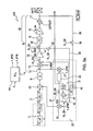
- FIG. 1 shows a known analyzing device and analyzing circuit for the known yaw rate sensor which is shown in a highly schematic form.
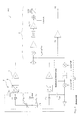
- FIG. 2 shows a known extension of the analyzing circuit in FIG. 1 with a quadrature control loop to suppress strong interference.
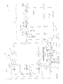
- FIG. 3 a shows an analyzing circuit according to the present invention for the known yaw rate sensor, which is shown in a highly schematic form, the switch positions of the switches according to the present invention for normal controller operation being shown.
- FIG. 3 b shows the analyzing circuit according to the present invention of FIG. 3 a , the switch positions of the switches according to the present invention for the balancing condition being shown.
- FIG. 4 shows the known yaw rate sensor in detail and the known analyzing circuit according to FIG. 2 .
- FIG. 5 shows the known yaw rate sensor in detail and the analyzing circuit according to the present invention according to FIG. 3 a.
- a CVG has a drive loop which is used to cause a seismic mass to vibrate.
- An electric, path-proportional signal x picked off in the drive loop is used as an input signal for a PLL.
- a velocity-proportional signal v may also be processed.
- the drive loop is not shown as part of the description of the present invention since the present invention refers to the processing of the output signals of a CVG.
- FIG. 1 shows a combination 100 of a known yaw rate sensor 3 which is shown in a highly schematic form and a known analyzing device or analyzing circuit 8 , the analyzing device determining the yaw rate RATE OUT from the output signal of the sensor device, i.e., of the yaw rate sensor, i.e., of CVG 3 .
- the yaw rate-proportional Coriolis force F C causes a deflection ⁇ x on the oscillating mass, the deflection undergoing a phase shift ⁇ in relation to Coriolis force F C because of the mechanical transfer function x/F of CVG 3 in question.
- the output signal of the CVG is present as a voltage signal and after passing through an intermediate amplifier 6 having a gain factor g, it is further processed as voltage U in analyzing device 8 .
- signal U is demodulated with an in-phase, velocity-proportional signal. Rectangular signals x_prop and v_prop used for this purpose are provided separately by a phase-locked loop or PLL 10 from input signals x and ⁇ . x_prop is in phase with signal x. v_prop is phase-shifted by 90° in relation to signal x. The signals are used for in-phase synchronous demodulation.
- a CVG exhibits interference signals QUAD that are not proportional to velocity but rather are proportional to and in phase with the path.
- the interference signals may possibly be very much greater than RATE OUT, the yaw rate signal to be actually measured.
- Demodulation signal v_prop which is obtained from PLL 10 , is therefore also phase shifted by ⁇ in order to determine yaw rate RATE OUT precisely and to prevent components of the quadrature signal, i.e., interference signal QUAD in the output signal.
- input signal U of analyzing unit 8 is demodulated in a signal path 12 according to QUAD (x_prop) by supplying it in succession to a mixer or multiplier 13 , an amplifier 14 , a low-pass filter 15 and an amplifier 16 having adjustable gain g_var. Offset balancing takes place at a summer 17 so that quadrature signal QUAD may be picked off as a signal at an output OUT.
- amplified yaw rate signal U of angular sensor 3 is applied at described signal path 12 and phase angle ⁇ is changed until no effect by the yaw rate can be observed at the signal output.
- this method can only be used if quadrature signals QUAD are so small that they do not overmodulate signal path 12 . If, however, interference signals QUAD are larger by several orders of magnitude tha yaw rate signal RATE OUT which is contained and is isolated, then a quadrature control loop 20 is provided. This has been done as an extension of the illustration of FIG. 1 in the circuit of FIG. 2 .
- Quadrature control loop 20 includes a first mixer 21 in which signal U amplified by a factor g by amplifier 6 is mixed with x_prop to form output signal UI after passage through a controller 22 .
- UI is mixed with auxiliary signal x_prop provided by PLL 10 once more in a second mixer 23 and is then sent in inverted form to a summer 25 together with the still not amplified output signal of CVG 3 in order to eliminate or substantially reduce interference signal QUAD.
- the balancing method described above with reference to FIG. 1 fails in a device according to FIG. 2 since quadrature control loop 20 suppresses the quadrature demodulated by the yaw rate signal at the output if the yaw rate signal of sensor 3 is applied and PLL 10 is incorrectly balanced. This means that the criterion for balancing phase angle ⁇ of PLL 10 is lacking. Rather, a signal at an output of controller 22 is now used as a balancing criterion in this case. At the output of controller 22 , very small V/°( ⁇ ) signals are produced, which are made even smaller with a large capture range of controller 22 .
- wN useful frequency or yaw rate
- g_var it is possible to balance the desired sensitivity of entire combination 300 in amplifier 16 .
- Gvar variable gain for sensitivity balancing
- the signal processing is able to process the quadrature signal in a linear manner until the synchronous demodulation.
- a quadrature control loop 20 is provided in the system which path (quadrature) demodulates amplitude-modulated signal U by multiplication with x_prop, FIG. 2 .
- This signal is supplied via a controller 22 which is an I-controller and integrates the signal.
- output signal UI is “held against” the quadrature signal coming from sensor element 3 at summer 25 .
- Summer 25 reduces the quadrature component of voltage U to zero except for a very small, residual deviation.
- FIG. 4 shows the known yaw rate sensor in greater detail and the known analyzing circuit according to FIG. 2 .
- the major function blocks and connecting elements e.g., CVG 3 , analyzing device 8 , quadrature control loop 20 , etc.
- the capture range of quadrature control loop 20 results in:
- the maximum allowable ⁇ C Quad is:
- ⁇ C Quad and ⁇ UI are understood to be the amplitudes of the corresponding sinusoidal oscillations. From (5), it is apparent that the quadrature controller capture range may also be expanded by enlarging CQ 1 , 2 , and a minimum CQ 1 , 2 is used for a capture range.
- the first term in the square brackets is the yaw rate which remains nearly uninfluenced (for ⁇ ⁇ 1°) by the quadrature control loop.
- the second term is in phase with the quadrature and is therefore detected and suppressed by the quadrature control loop.
- Balancing is carried out in the devices of FIGS. 2 and 4 according to the related art in such a way that with an applied constant yaw rate, all balancing bits of the PLL balancing are selected and the output signal of controller 22 is recorded. The same procedure is repeated with an opposite sign at the same yaw rate. The point of intersection of both characteristics denotes the correct balancing combination.
- small balancing values are difficult to detect during production. The problem may be corrected by using an additional amplifier.
- quadrature signal QUAD present at the controller output in any case, which may be much larger than the balancing signal, is also amplified.
- FIG. 3 a A device according to the present invention to solve this problem is shown in FIG. 3 a .
- the extended circuit of analyzing device 8 is added via switches 35 , 36 in signal path 12 , a switch 37 in quadrature control loop 20 , and one switch 38 , 39 each in feedback branch 30 and connecting branch 32 . It is possible to change the switch position of switches marked 35 , 36 , 37 , 38 , 39 by a logical “1” via a FLAG RL_QH which may be activated by software during balancing.
- Attenuating branch or tuning branch 31 is connected between the output of controller 22 and the input of the amplifier or impedance transformer 47 .
- Attenuating branch 31 has an attenuating element 42 which has an attenuation factor K 2 , a summer 44 , a coupling element 46 which supplies the output signal weighted with a factor K 1 to summer 44 via feedback branch 30 , and an impedance transformer 47 which is connected between the output of summer 44 and the input of mixer 23 .
- the input of coupling element 46 is connected with RATE OUT; a separate input for this purpose may also be provided in an alterative embodiment.
- the following method is preferred for the quadrature adjustment of PLL 10 and analyzing device 8 :
- this voltage UI Qaud is applied to coupling element K 1 via the offset balancing, which is present in any case with RATE OUT.
- Signal path 12 is simultaneously connected to the signal ground or frame via switch 36 in order only to have the effect of the offset balancing at the signal output.
- Signal UI at the output of controller 22 is set to the signal ground or frame, i.e., nothing additional is fed in since the voltage used to suppress the quadrature is already made available via coupling element K 1 .
- K 2 ⁇ 1 may be selected, it is possible to significantly increase the balancing sensitivity.
- the correct balancing combination is now determined again as was described above referring to the related art according to FIG. 2 .
- CQ 1 , 2 may not fall below a minimum value derived from the quadrature capture range; therefore, the balancing sensitivity may also increased via 1/K 2 >>1 with given U HF and ⁇ C.
- the adjustment of the balancing sensitivity is thus decoupled from the quadrature capture range and is carried out with substantially improved precision.
- the normal control operation is adjusted in the tuned control device.
- FIG. 4 shows a combination 400 of known yaw rate sensor 3 , which is shown in greater detail compared to FIG. 1, and known analyzing circuit 8 according to FIG. 2 .
- FIG. 5 shows a combination 500 of known yaw rate sensor 3 , which is shown in greater detail compared to FIG. 1, and the analyzing device/analyzing circuit of the present invention according to FIG. 3 a .
- FIGS. 4 and 5 For the sake of clarity, only the reference symbols of the major function blocks of FIGS. 2 and 3 a are indicated in FIGS. 4 and 5.
- the quadrature voltage is applied to coupling unit K 1 externally via a separate pin or terminal (not shown).
Landscapes
- Physics & Mathematics (AREA)
- Engineering & Computer Science (AREA)
- General Physics & Mathematics (AREA)
- Radar, Positioning & Navigation (AREA)
- Remote Sensing (AREA)
- Gyroscopes (AREA)
- Steering Control In Accordance With Driving Conditions (AREA)
Applications Claiming Priority (4)
| Application Number | Priority Date | Filing Date | Title |
|---|---|---|---|
| DE10062347A DE10062347A1 (de) | 2000-12-14 | 2000-12-14 | Verfahren zum Abgleichen des Phasenregelkreises einer elektronischen Auswertevorrichtung sowie eine elektronische Auswertevorrichtung |
| DE10062347.6 | 2000-12-14 | ||
| DE10062347 | 2000-12-14 | ||
| PCT/DE2001/004561 WO2002048649A1 (de) | 2000-12-14 | 2001-12-04 | Verfahren zum abgleichen des phasenregelkreises einre elektronischen auswertungsvorrichtung sowie eine elektronische auswertungsvorrichtung |
Publications (2)
| Publication Number | Publication Date |
|---|---|
| US20030121307A1 US20030121307A1 (en) | 2003-07-03 |
| US6672159B2 true US6672159B2 (en) | 2004-01-06 |
Family
ID=7667141
Family Applications (1)
| Application Number | Title | Priority Date | Filing Date |
|---|---|---|---|
| US10/203,861 Expired - Lifetime US6672159B2 (en) | 2000-12-14 | 2001-12-04 | Method for adjusting the phase-locking loop of an electronic evaluation device and corresponding electronic evaluation device |
Country Status (6)
| Country | Link |
|---|---|
| US (1) | US6672159B2 (de) |
| EP (1) | EP1348105B1 (de) |
| JP (1) | JP4518461B2 (de) |
| KR (1) | KR100810839B1 (de) |
| DE (2) | DE10062347A1 (de) |
| WO (1) | WO2002048649A1 (de) |
Cited By (5)
| Publication number | Priority date | Publication date | Assignee | Title |
|---|---|---|---|---|
| US20110101955A1 (en) * | 2009-11-05 | 2011-05-05 | Texas Instruments Incorporated | System and method for implementing low-cost electronic gyroscopes and accelerometer |
| US20110197675A1 (en) * | 2010-02-16 | 2011-08-18 | Stmicroelectronics S.R.L. | Microelectromechanical gyroscope with inversion of actuation forces, and method for actuating a microelectromechanical gyroscope |
| US20120136632A1 (en) * | 2009-05-27 | 2012-05-31 | Balslink Thorsten | Sensor and method for operating a sensor |
| US20120186345A1 (en) * | 2009-05-19 | 2012-07-26 | Wolfram Bauer | Self-test for yaw rate sensors |
| US20130170091A1 (en) * | 2008-12-11 | 2013-07-04 | Stmicroelectronics S.R.L. | Variable capacitance electronic device and microelectromechanical device incorporating such electronic device |
Families Citing this family (12)
| Publication number | Priority date | Publication date | Assignee | Title |
|---|---|---|---|---|
| US20030194755A1 (en) * | 2001-04-27 | 2003-10-16 | Genoptix, Inc. | Early detection of apoptotic events and apoptosis using optophoretic analysis |
| US20040009540A1 (en) * | 2001-04-27 | 2004-01-15 | Genoptix, Inc | Detection and evaluation of cancer cells using optophoretic analysis |
| US20040023310A1 (en) * | 2001-04-27 | 2004-02-05 | Genoptix, Inc | Quantitative determination of protein kinase C activation using optophoretic analysis |
| US20030211461A1 (en) * | 2002-05-01 | 2003-11-13 | Genoptix, Inc | Optophoretic detection of durgs exhibiting inhibitory effect on Bcr-Abl positive tumor cells |
| DE10248735B4 (de) | 2002-10-18 | 2004-10-28 | Litef Gmbh | Verfahren zur elektronischen Abstimmung der Ausleseschwingungsfrequenz eines Corioliskreisels |
| DE10248734B4 (de) | 2002-10-18 | 2004-10-28 | Litef Gmbh | Verfahren zur elektronischen Abstimmung der Ausleseschwingungsfrequenz eines Corioliskreisels |
| DE10248733B4 (de) | 2002-10-18 | 2004-10-28 | Litef Gmbh | Verfahren zur elektronischen Abstimmung der Ausleseschwingungsfrequenz eines Corioliskreisels |
| DE10317159B4 (de) | 2003-04-14 | 2007-10-11 | Litef Gmbh | Verfahren zur Kompensation eines Nullpunktfehlers in einem Corioliskreisel |
| US6934665B2 (en) * | 2003-10-22 | 2005-08-23 | Motorola, Inc. | Electronic sensor with signal conditioning |
| CN107947787A (zh) * | 2017-11-21 | 2018-04-20 | 北京金自天正智能控制股份有限公司 | 一种应用于大功率三电平背靠背pwm变流器的系统自适应锁相环方法 |
| DE102018222608B4 (de) | 2018-12-20 | 2021-06-10 | Robert Bosch Gmbh | System mit mikromechanischer taktgebender Systemkomponente |
| US11196430B2 (en) | 2020-02-19 | 2021-12-07 | Honeywell International Inc. | High-bandwidth phase lock loop circuit with sideband rejection |
Citations (5)
| Publication number | Priority date | Publication date | Assignee | Title |
|---|---|---|---|---|
| US5287033A (en) * | 1990-08-24 | 1994-02-15 | British Aerospace Public Limited Company | Vibrating surface gyroscopes |
| US5379223A (en) | 1992-06-19 | 1995-01-03 | Alliedsignal Inc. | Inertial measurement and navigation system using digital signal processing techniques |
| US5600064A (en) | 1994-03-28 | 1997-02-04 | The Charles Stark Draper Laboratory, Inc. | Electronics for coriolis force and other sensors |
| US5850035A (en) | 1995-06-07 | 1998-12-15 | Bei Sensors & Systems Company, Inc. | Closed loop resonant rotation rate sensor |
| US6067858A (en) | 1996-05-31 | 2000-05-30 | The Regents Of The University Of California | Micromachined vibratory rate gyroscope |
Family Cites Families (1)
| Publication number | Priority date | Publication date | Assignee | Title |
|---|---|---|---|---|
| US585035A (en) * | 1897-06-22 | Track-sanding apparatus |
-
2000
- 2000-12-14 DE DE10062347A patent/DE10062347A1/de not_active Ceased
-
2001
- 2001-12-04 WO PCT/DE2001/004561 patent/WO2002048649A1/de not_active Ceased
- 2001-12-04 EP EP01989364A patent/EP1348105B1/de not_active Expired - Lifetime
- 2001-12-04 DE DE50115354T patent/DE50115354D1/de not_active Expired - Lifetime
- 2001-12-04 KR KR1020027010465A patent/KR100810839B1/ko not_active Expired - Lifetime
- 2001-12-04 JP JP2002549912A patent/JP4518461B2/ja not_active Expired - Lifetime
- 2001-12-04 US US10/203,861 patent/US6672159B2/en not_active Expired - Lifetime
Patent Citations (5)
| Publication number | Priority date | Publication date | Assignee | Title |
|---|---|---|---|---|
| US5287033A (en) * | 1990-08-24 | 1994-02-15 | British Aerospace Public Limited Company | Vibrating surface gyroscopes |
| US5379223A (en) | 1992-06-19 | 1995-01-03 | Alliedsignal Inc. | Inertial measurement and navigation system using digital signal processing techniques |
| US5600064A (en) | 1994-03-28 | 1997-02-04 | The Charles Stark Draper Laboratory, Inc. | Electronics for coriolis force and other sensors |
| US5850035A (en) | 1995-06-07 | 1998-12-15 | Bei Sensors & Systems Company, Inc. | Closed loop resonant rotation rate sensor |
| US6067858A (en) | 1996-05-31 | 2000-05-30 | The Regents Of The University Of California | Micromachined vibratory rate gyroscope |
Cited By (12)
| Publication number | Priority date | Publication date | Assignee | Title |
|---|---|---|---|---|
| US20130170091A1 (en) * | 2008-12-11 | 2013-07-04 | Stmicroelectronics S.R.L. | Variable capacitance electronic device and microelectromechanical device incorporating such electronic device |
| US8667842B2 (en) * | 2008-12-11 | 2014-03-11 | Stmicroelectronics S.R.L. | Variable capacitance electronic device and microelectromechanical device incorporating such electronic device |
| US20120186345A1 (en) * | 2009-05-19 | 2012-07-26 | Wolfram Bauer | Self-test for yaw rate sensors |
| US8910518B2 (en) * | 2009-05-19 | 2014-12-16 | Robert Bosch Gmbh | Self-test for yaw rate sensors |
| US9863781B2 (en) | 2009-05-19 | 2018-01-09 | Robert Bosch Gmbh | Self-test for yaw rate sensors |
| US20120136632A1 (en) * | 2009-05-27 | 2012-05-31 | Balslink Thorsten | Sensor and method for operating a sensor |
| US10030975B2 (en) * | 2009-05-27 | 2018-07-24 | Robert Bosch Gmbh | Sensor and method for operating a sensor |
| US20110101955A1 (en) * | 2009-11-05 | 2011-05-05 | Texas Instruments Incorporated | System and method for implementing low-cost electronic gyroscopes and accelerometer |
| WO2011056908A3 (en) * | 2009-11-05 | 2011-08-18 | Texas Instruments Incorporated | System and method for implementing low-cost electronic gyroscopes and accelerometer |
| US8258774B2 (en) | 2009-11-05 | 2012-09-04 | Texas Instruments Incorporated | System and method for implementing low-cost electronic gyroscopes and accelerometer |
| US20110197675A1 (en) * | 2010-02-16 | 2011-08-18 | Stmicroelectronics S.R.L. | Microelectromechanical gyroscope with inversion of actuation forces, and method for actuating a microelectromechanical gyroscope |
| US8714012B2 (en) | 2010-02-16 | 2014-05-06 | Stmicroelectronics S.R.L. | Microelectromechanical gyroscope with inversion of actuation forces, and method for actuating a microelectromechanical gyroscope |
Also Published As
| Publication number | Publication date |
|---|---|
| DE50115354D1 (de) | 2010-04-01 |
| DE10062347A1 (de) | 2002-06-20 |
| JP2004515774A (ja) | 2004-05-27 |
| JP4518461B2 (ja) | 2010-08-04 |
| WO2002048649A1 (de) | 2002-06-20 |
| EP1348105A1 (de) | 2003-10-01 |
| KR20020077437A (ko) | 2002-10-11 |
| US20030121307A1 (en) | 2003-07-03 |
| EP1348105B1 (de) | 2010-02-17 |
| KR100810839B1 (ko) | 2008-03-07 |
Similar Documents
| Publication | Publication Date | Title |
|---|---|---|
| US6672159B2 (en) | Method for adjusting the phase-locking loop of an electronic evaluation device and corresponding electronic evaluation device | |
| JP7115509B2 (ja) | ジャイロスコープの連続セルフテスト | |
| EP2447671A1 (de) | Winkelgeschwindigkeitssensor und synchrone detektionsschaltung dafür | |
| JPS5897925A (ja) | 高周波送信機における送信管の陽極負荷インピ−ダンスの最適値検出装置 | |
| US6467346B1 (en) | Coriolis sensor interface | |
| US6230562B1 (en) | Detection circuit for vibratory gyro and vibratory gyro device using the same | |
| US5185585A (en) | Crystal oscillator and method with amplitude and phase control | |
| US20040196617A1 (en) | Capacitance-sensing vibratory gyro and method for detecting change in capacitance | |
| EP2733461B1 (de) | Amplitudensteuerung für vibrierende Resonanzsensoren | |
| US20260035235A1 (en) | Method and apparatus for evaluating electrostatic or nonlinear devices | |
| AU2004227053B2 (en) | Method for determining a zero-point error in a vibratory gyroscope | |
| US7188522B2 (en) | Method for aligning a rotation rate sensor | |
| US5978084A (en) | Open loop signal processing circuit and method for a fiber optic interferometric sensor | |
| CN114006616A (zh) | 自适应相位对准电路、调试方法及陀螺仪测控电路 | |
| US6374671B1 (en) | Method of stimulating an oscillator control for capacitive measurement of strength, acceleration and/or rotation speed | |
| US4542346A (en) | Wide-range lock-in amplifier | |
| CN115876221A (zh) | 基于参量激励的mems陀螺驱动力偏转角的辨识以及抑制方法 | |
| US6661232B1 (en) | Electric potential sensor and electronic apparatus using the same | |
| GB2424706A (en) | Solid-state gyroscopes | |
| CN111435091B (zh) | 自适应相位对准模块和方法、及振动式陀螺仪测控电路 | |
| JPH11502015A (ja) | 電気的攪乱信号の電子的補償方法並びに装置とその使用 | |
| SU1408321A1 (ru) | Спектрометр ЯМР широких линий | |
| CN102843114A (zh) | 带宽可调的零相移rc低通滤波器 | |
| SU813296A1 (ru) | Устройство дл измерени девиациичАСТОТы | |
| JPS63142249A (ja) | 電子スピン共鳴装置 |
Legal Events
| Date | Code | Title | Description |
|---|---|---|---|
| AS | Assignment |
Owner name: ROBERT BOSCH GMBH, GERMANY Free format text: ASSIGNMENT OF ASSIGNORS INTEREST;ASSIGNORS:SCHMID, FRANK;MOHAUPT, JENS;BAUER, WOLFRAM;REEL/FRAME:013491/0062;SIGNING DATES FROM 20020923 TO 20020930 |
|
| FEPP | Fee payment procedure |
Free format text: PAYOR NUMBER ASSIGNED (ORIGINAL EVENT CODE: ASPN); ENTITY STATUS OF PATENT OWNER: LARGE ENTITY |
|
| STCF | Information on status: patent grant |
Free format text: PATENTED CASE |
|
| CC | Certificate of correction | ||
| FPAY | Fee payment |
Year of fee payment: 4 |
|
| FPAY | Fee payment |
Year of fee payment: 8 |
|
| FPAY | Fee payment |
Year of fee payment: 12 |