US6699428B2 - Ceramic body producing method - Google Patents
Ceramic body producing method Download PDFInfo
- Publication number
- US6699428B2 US6699428B2 US10/030,434 US3043402A US6699428B2 US 6699428 B2 US6699428 B2 US 6699428B2 US 3043402 A US3043402 A US 3043402A US 6699428 B2 US6699428 B2 US 6699428B2
- Authority
- US
- United States
- Prior art keywords
- cells
- face
- ceramic honeycomb
- mask
- formed body
- Prior art date
- Legal status (The legal status is an assumption and is not a legal conclusion. Google has not performed a legal analysis and makes no representation as to the accuracy of the status listed.)
- Expired - Fee Related, expires
Links
Images




Classifications
-
- B—PERFORMING OPERATIONS; TRANSPORTING
- B01—PHYSICAL OR CHEMICAL PROCESSES OR APPARATUS IN GENERAL
- B01D—SEPARATION
- B01D46/00—Filters or filtering processes specially modified for separating dispersed particles from gases or vapours
- B01D46/24—Particle separators, e.g. dust precipitators, using rigid hollow filter bodies
- B01D46/2403—Particle separators, e.g. dust precipitators, using rigid hollow filter bodies characterised by the physical shape or structure of the filtering element
- B01D46/2418—Honeycomb filters
-
- B—PERFORMING OPERATIONS; TRANSPORTING
- B01—PHYSICAL OR CHEMICAL PROCESSES OR APPARATUS IN GENERAL
- B01D—SEPARATION
- B01D46/00—Filters or filtering processes specially modified for separating dispersed particles from gases or vapours
- B01D46/0001—Making filtering elements
-
- B—PERFORMING OPERATIONS; TRANSPORTING
- B28—WORKING CEMENT, CLAY, OR STONE
- B28B—SHAPING CLAY OR OTHER CERAMIC COMPOSITIONS; SHAPING SLAG; SHAPING MIXTURES CONTAINING CEMENTITIOUS MATERIAL, e.g. PLASTER
- B28B11/00—Apparatus or processes for treating or working the shaped or preshaped articles
- B28B11/003—Apparatus or processes for treating or working the shaped or preshaped articles the shaping of preshaped articles, e.g. by bending
- B28B11/006—Making hollow articles or partly closed articles
-
- B—PERFORMING OPERATIONS; TRANSPORTING
- B28—WORKING CEMENT, CLAY, OR STONE
- B28B—SHAPING CLAY OR OTHER CERAMIC COMPOSITIONS; SHAPING SLAG; SHAPING MIXTURES CONTAINING CEMENTITIOUS MATERIAL, e.g. PLASTER
- B28B11/00—Apparatus or processes for treating or working the shaped or preshaped articles
- B28B11/003—Apparatus or processes for treating or working the shaped or preshaped articles the shaping of preshaped articles, e.g. by bending
- B28B11/006—Making hollow articles or partly closed articles
- B28B11/007—Using a mask for plugging
-
- C—CHEMISTRY; METALLURGY
- C04—CEMENTS; CONCRETE; ARTIFICIAL STONE; CERAMICS; REFRACTORIES
- C04B—LIME, MAGNESIA; SLAG; CEMENTS; COMPOSITIONS THEREOF, e.g. MORTARS, CONCRETE OR LIKE BUILDING MATERIALS; ARTIFICIAL STONE; CERAMICS; REFRACTORIES; TREATMENT OF NATURAL STONE
- C04B38/00—Porous mortars, concrete, artificial stone or ceramic ware; Preparation thereof
- C04B38/0006—Honeycomb structures
-
- C—CHEMISTRY; METALLURGY
- C04—CEMENTS; CONCRETE; ARTIFICIAL STONE; CERAMICS; REFRACTORIES
- C04B—LIME, MAGNESIA; SLAG; CEMENTS; COMPOSITIONS THEREOF, e.g. MORTARS, CONCRETE OR LIKE BUILDING MATERIALS; ARTIFICIAL STONE; CERAMICS; REFRACTORIES; TREATMENT OF NATURAL STONE
- C04B38/00—Porous mortars, concrete, artificial stone or ceramic ware; Preparation thereof
- C04B38/0006—Honeycomb structures
- C04B38/0012—Honeycomb structures characterised by the material used for sealing or plugging (some of) the channels of the honeycombs
-
- F—MECHANICAL ENGINEERING; LIGHTING; HEATING; WEAPONS; BLASTING
- F01—MACHINES OR ENGINES IN GENERAL; ENGINE PLANTS IN GENERAL; STEAM ENGINES
- F01N—GAS-FLOW SILENCERS OR EXHAUST APPARATUS FOR MACHINES OR ENGINES IN GENERAL; GAS-FLOW SILENCERS OR EXHAUST APPARATUS FOR INTERNAL-COMBUSTION ENGINES
- F01N3/00—Exhaust or silencing apparatus having means for purifying, rendering innocuous, or otherwise treating exhaust
- F01N3/02—Exhaust or silencing apparatus having means for purifying, rendering innocuous, or otherwise treating exhaust for cooling, or for removing solid constituents of, exhaust
- F01N3/021—Exhaust or silencing apparatus having means for purifying, rendering innocuous, or otherwise treating exhaust for cooling, or for removing solid constituents of, exhaust by means of filters
- F01N3/022—Exhaust or silencing apparatus having means for purifying, rendering innocuous, or otherwise treating exhaust for cooling, or for removing solid constituents of, exhaust by means of filters characterised by specially adapted filtering structure, e.g. honeycomb, mesh or fibrous
- F01N3/0222—Exhaust or silencing apparatus having means for purifying, rendering innocuous, or otherwise treating exhaust for cooling, or for removing solid constituents of, exhaust by means of filters characterised by specially adapted filtering structure, e.g. honeycomb, mesh or fibrous the structure being monolithic, e.g. honeycombs
-
- F—MECHANICAL ENGINEERING; LIGHTING; HEATING; WEAPONS; BLASTING
- F01—MACHINES OR ENGINES IN GENERAL; ENGINE PLANTS IN GENERAL; STEAM ENGINES
- F01N—GAS-FLOW SILENCERS OR EXHAUST APPARATUS FOR MACHINES OR ENGINES IN GENERAL; GAS-FLOW SILENCERS OR EXHAUST APPARATUS FOR INTERNAL-COMBUSTION ENGINES
- F01N2330/00—Structure of catalyst support or particle filter
- F01N2330/06—Ceramic, e.g. monoliths
-
- F—MECHANICAL ENGINEERING; LIGHTING; HEATING; WEAPONS; BLASTING
- F01—MACHINES OR ENGINES IN GENERAL; ENGINE PLANTS IN GENERAL; STEAM ENGINES
- F01N—GAS-FLOW SILENCERS OR EXHAUST APPARATUS FOR MACHINES OR ENGINES IN GENERAL; GAS-FLOW SILENCERS OR EXHAUST APPARATUS FOR INTERNAL-COMBUSTION ENGINES
- F01N3/00—Exhaust or silencing apparatus having means for purifying, rendering innocuous, or otherwise treating exhaust
- F01N3/08—Exhaust or silencing apparatus having means for purifying, rendering innocuous, or otherwise treating exhaust for rendering innocuous
- F01N3/10—Exhaust or silencing apparatus having means for purifying, rendering innocuous, or otherwise treating exhaust for rendering innocuous by thermal or catalytic conversion of noxious components of exhaust
- F01N3/24—Exhaust or silencing apparatus having means for purifying, rendering innocuous, or otherwise treating exhaust for rendering innocuous by thermal or catalytic conversion of noxious components of exhaust characterised by constructional aspects of converting apparatus
- F01N3/28—Construction of catalytic reactors
- F01N3/2803—Construction of catalytic reactors characterised by structure, by material or by manufacturing of catalyst support
- F01N3/2825—Ceramics
- F01N3/2828—Ceramic multi-channel monoliths, e.g. honeycombs
-
- Y—GENERAL TAGGING OF NEW TECHNOLOGICAL DEVELOPMENTS; GENERAL TAGGING OF CROSS-SECTIONAL TECHNOLOGIES SPANNING OVER SEVERAL SECTIONS OF THE IPC; TECHNICAL SUBJECTS COVERED BY FORMER USPC CROSS-REFERENCE ART COLLECTIONS [XRACs] AND DIGESTS
- Y02—TECHNOLOGIES OR APPLICATIONS FOR MITIGATION OR ADAPTATION AGAINST CLIMATE CHANGE
- Y02T—CLIMATE CHANGE MITIGATION TECHNOLOGIES RELATED TO TRANSPORTATION
- Y02T10/00—Road transport of goods or passengers
- Y02T10/10—Internal combustion engine [ICE] based vehicles
- Y02T10/12—Improving ICE efficiencies
Definitions
- the present invention relates to a method of producing a ceramic body having a construction such that cells are plugged alternately at both end faces of a ceramic honeycomb structural body.
- FIGS. 15 a - 15 c are schematic views respectively explaining one embodiment of a method of producing such a known ceramic body.
- FIGS. 15 a - 15 c one embodiment of the known method of producing the ceramic body will be explained.
- a mask 54 made of rubber having holes 53 corresponding to cells 52 to be plugged at an end face of a ceramic honeycomb formed body 51 (ceramic honeycomb structural body before sintering) is prepared, and the thus prepared mask 54 is set at a predetermined position on the end face of the ceramic honeycomb formed body 51 by hand.
- the end face of the ceramic honeycomb formed body 51 to which thee mask 54 is set, is immersed in a plugging slurry 55 , and, a pressure is applied to the ceramic honeycomb formed body 51 from above, so that the cells 52 are filled with the slurry 55 through the holes 53 of the mask 54 .
- predetermined cells 52 are filled with the slurry 55 in the same manner.
- a mask having a reverse hole pattern such that holes are arranged at portions where no holes 53 of the mask 54 are arranged is used so as to obtain a construction such that the cells 52 are plugged alternately at both end faces of the ceramic honeycomb structural body.
- FIG. 15 c by cross section it is possible to obtain the ceramic honeycomb formed body 51 having a construction such that the cells 2 are plugged alternately at its both end faces.
- An object of the invention is to eliminate the drawbacks mentioned above and to provide a method of producing a ceramic body which can easily plug cells at an end face and which can be easily automated.
- a method of producing a ceramic body having a construction such that cells are plugged alternately at both end faces of a ceramic honeycomb structural body by filling a plugging slurry into predetermined cells at both end faces of a ceramic honeycomb formed body comprises the steps of: filling a plugging material for mask into the cells to be opened at one end face of the ceramic honeycomb formed body; immersing the end face, to which the plugging material for mask is filled, into a plugging slurry; and drying and sintering the ceramic honeycomb formed body while the plugging material for mask is removed during a drying step or a sintering step.
- the plugging operation of the end face of the ceramic honeycomb structural body is performed by using a plugging material for mask which can be removed at the sintering without using a mask, it is possible to eliminate a production of the mask and a setting operation of the mask with respect to the end face of the ceramic honeycomb structural body. Moreover, since a filling operation of various plugging materials for mask mentioned below can be easily automated, the plugging operation of the ceramic body according to the invention can be also automated.
- the plugging material for mask filling step further comprises the steps of: preparing a suction jig having a same honeycomb construction as that of the ceramic honeycomb formed body; adhering a mask, in which holes are arranged corresponding to the cells to be plugged, to one end face of the suction jig; sucking paraffin balls, a diameter of which is larger than a length of one side of the cell, to the predetermined cells at the other end face by sucking from the end face to which the mask is adhered; setting the suction jig, to which paraffin balls are sucked, to the end face of the ceramic honeycomb formed body to which the plugging material is to be filled; aligning the paraffin balls to the cells to be opened by stopping the sucking operation; inserting the thus aligned paraffin balls into the cells by applying pressure; and filling the paraffin balls into the cells to be opened as the plugging material for mask.
- the plugging material for mask filling step further comprises the steps of: making a mask for respective ceramic honeycomb formed bodies by piercing a sheet adhered to one end face of the ceramic honeycomb formed body at positions corresponding to the cells to be plugged; immersing the one end face to which the mask is adhered into a liquid paraffin; inserting the liquid paraffin into the cells through the holes of the mask by applying a pressure; and filling the liquid paraffin into the cells to be opened as the plugging material for mask.
- the plugging material for mask filling step further comprises the steps of: immersing one end face of the ceramic honeycomb formed body into a photo-curing resin before hardening; emanating a light to the photo-curing resin from the other end face through a mask, in which a light is transmitted only to the cells to be opened, so as to harden the photo-curing resin; and filling the photo-curing resin into the cells to be opened as the plugging material for mask.
- FIGS. 1 a - 1 c are schematic view respectively explaining one step of a paraffin ball filling method as one example of a method of producing a ceramic body according to the invention.
- FIGS. 2 a - 2 d are schematic views respectively explaining another step in the method shown in FIG. 1 .
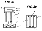
- FIGS. 3 a and 3 b are schematic views respectively explaining still another step in the method shown in FIG. 1 .
- FIGS. 4 a - 4 c are schematic views respectively explaining still another step in the method shown in FIG. 1 .
- FIG. 5 is a schematic view showing one embodiment of a ceramic body according to the invention.
- FIGS. 6 a and 6 b are schematic views respectively showing one embodiment of a paraffin ball aligning method in the embodiment shown in FIG. 1 .
- FIGS. 7 a - 7 d are schematic views respectively showing another example of a paraffin ball aligning method in the embodiment method in the embodiment shown in FIG. 1 .
- FIG. 8 is a schematic view explaining one step of a liquid paraffin filling method as another example of a method of producing a ceramic body according to the invention.
- FIGS. 9 a and 9 b are schematic views respectively explaining another step in the embodiment shown in FIG. 8 .
- FIGS. 10 a and 10 b are schematic views respectively explaining still another step in the embodiment shown in FIG. 8 .
- FIGS. 11 a - 11 c are schematic views respectively explaining still another step in the embodiment shown in FIG. 8 .
- FIG. 12 is a schematic view explaining one step of a photo-curing resin filling method as still another example of a method of producing a ceramic body according to the invention.
- FIGS. 13 a - 13 c are schematic views respectively explaining another step in the embodiment shown in FIG. 12 .
- FIGS. 14 a and 14 b are schematic view respectively explaining still another in the embodiment shown in FIG. 12 .
- FIGS. 15 a - 15 c are schematic views respectively explaining one embodiment of the known method of producing a ceramic body.
- the most important features of the invention is to perform the steps of: filling a plugging material for mask such as paraffin and photo-curing resin into cells to be opened of a ceramic honeycomb formed body; filling a plugging slurry into the cells to which the plugging material for mask is not filled; sintering the ceramic honeycomb formed body; and removing the plugging material for mask at the sintering step.
- a plugging material for mask such as paraffin and photo-curing resin
- paraffin balls 3 having a diameter larger than a length of one side of cell 2 constituting a ceramic honeycomb formed body 1 are prepared, and the thus prepared paraffin balls 3 are aligned in a checkered pattern on the cells 2 to be opened at an end face of the ceramic honeycomb formed body 1 .
- a method of aligning the paraffin balls 3 will be explained hereinafter in detail.
- the paraffin balls 3 are shown larger as compared with their actual size so as to see them.
- the paraffin balls 3 After aligning the paraffin balls 3 on the end face, as shown in FIGS. 2 a and 2 b , the paraffin balls 3 are inserted into the cells by applying a pressure thereto. In this case, the paraffin ball 3 is ground or deformed by a wall of the cell 2 , and a space occurs between the paraffin ball 3 and an inner wall of the cell 2 . Therefore, as shown in FIGS. 2 c and 2 d , the paraffin ball 3 is softened by heat and adapted to the inner wall of the cell 2 without spaces.
- the ceramic honeycomb formed body 1 is set to a vacuum apparatus 4 which can function to vacuum only a center portion other than an outer peripheral portion of the ceramic honeycomb formed body 1 under a condition such that the end face of the ceramic honeycomb formed body 1 after the paraffin balls 3 are inserted into the predetermined cells 2 is positioned upward. Under such a condition, the ceramic honeycomb formed body 1 approaches to a tray 5 in which the paraffin balls 3 are filled, and the vacuum apparatus 4 starts to work.
- a vacuum state occurs only at the cells 2 to which the paraffin balls 3 are not filled at an upper end face of the ceramic honeycomb formed body 1 , and thus the paraffin balls 3 are sucked to the predetermined cells 2 at an under end face.
- the paraffin balls 3 are inserted into the cells 2 .
- the paraffin balls 3 are filled into the cells 2 to be opened at the both end faces of the ceramic honeycomb formed body 1 as a plugging material for mask.
- the end face of the thus obtained ceramic honeycomb formed body 1 is immersed into a plugging slurry 7 stored in a vessel 6 .
- the plugging slurry 7 is filled into the predetermined cells 2 , to which the paraffin balls 3 are not filled, by applying a pressure to the ceramic honeycomb formed body 1 from upward by means of a pressurized means 8 .
- the same operations are performed repeatedly with respect to the other end face.
- FIG. 4 c it is possible to obtain the ceramic honeycomb formed body 1 in which the plugging slurry 7 is filled into the cells 2 at the both end faces to which the paraffin balls 2 are not filled.
- the thus obtained ceramic honeycomb formed body 1 is sintered as is the same manner as that of the known manner after drying.
- the plugging slurry 7 is dried and sintered so as to integrate with a cell wall 9 .
- the paraffin balls 3 are melted and removed.
- FIG. 5 it is possible to obtain a ceramic body 10 having a construction such that the cells 2 are plugged alternately at the both end faces of the ceramic honeycomb structural body.
- the method of filling the paraffin balls are finished.
- a preferable method of aligning the paraffin balls 3 to the predetermined cells 2 (a) method of utilizing a setter (formed body having the same honeycomb structure as that of the ceramic honeycomb formed body) as a paraffin ball suction jig, and (b) method of utilizing the ceramic honeycomb formed body itself as the paraffin ball suction jig will be explained.
- a setter 21 is formed simultaneously when the ceramic honeycomb formed body 1 is formed and is utilized as the suction jig.
- a mask 23 having a construction such that holes 22 are arranged in a checkered pattern at positions corresponding to the cells to be plugged is adhered to an upper face of the setter 21 .
- the mask 23 may be formed by rubber, resin, paper and so on.
- the setter 21 is set to the vacuum apparatus 4 in such a manner that the surface, to which the mask 23 is adhered, is positioned upward. Then, the setter 21 approaches to the tray 5 in which the paraffin balls 3 are stored, and the suction apparatus 4 starts to work. As a result, the paraffin balls 3 are sucked in a checkered pattern on an under face of the setter 21 .
- the setter 21 is set on the end face of the ceramic honeycomb formed body 1 positioned by for example an image processing apparatus, and the vacuum apparatus 4 is stopped. In this manner, the paraffin balls 3 are aligned to the end face of the ceramic honeycomb formed body 1 . Then, the same aligning operations are performed for the other end face by utilizing the setter 21 , to which another mask 23 is adhered, so that thee paraffin balls 3 can be aligned at the both end faces.
- the ceramic honeycomb formed body 1 in which the paraffin balls 3 are filled to the cells 2 at one end face, is utilized as the suction jig for filling the paraffin balls 3 to a next ceramic honeycomb formed body 1 .
- a ceramic honeycomb formed body 1 — 1 to which the mask 23 is adhered, is utilized for the first ceramic honeycomb formed body 1 .
- the paraffin balls 3 are aligned to the predetermined cells 2 at the end face of a next ceramic honeycomb formed body 1 - 2 in the same manner as that of the embodiment mentioned above except that the ceramic honeycomb formed body 1 — 1 is utilized as the setter 21 (FIG. 7 b ).
- the paraffin balls 3 are aligned to the predetermined cells 2 at the end face of a further next ceramic honeycomb formed body 1 - 3 (FIG. 7 d ) in the same manner as that of the embodiment mentioned above except that the ceramic honeycomb formed body 1 - 2 , in which the paraffin balls 3 are aligned at one end face, is utilized as the setter 21 (FIG. 7 c ). The above operations are repeated, so that the paraffin balls 3 are aligned at the both end faces.
- a sheet 32 having a dimension substantially equal to the end face of the ceramic honeycomb formed body 1 is prepared.
- the thus prepared sheet 32 is adhered to the overall end face, the cell positions of which are recognized.
- a commercially available adhesive sheet can be used as the sheet 32 .
- reference positions of small blocks defined according to a specification of the ceramic honeycomb formed body 1 such as outer diameter and cell pitch are calculated on the basis of the cell positions which are recognized by an image processing, and holes 33 are opened at the cell positions to be opened of the sheet 32 by means of a laser machining and so on, while the ceramic honeycomb formed body 1 is positioned by means of an XYZ ⁇ stage.
- the sheet 32 having the holes 33 functions as the mask.
- the hole 33 has a circular shape, and it is not necessary to open to an extent such that the hole 33 has the same (quadrangle) shape as that of the cell 2 .
- a diameter of the hole 33 is smaller than the cell 2 .
- FIGS. 11 a - 11 c a melted liquid paraffin 34 is filled into the cells 2 through the holes 33 of the sheet 32 . That is to say, as shown in FIG. 11 a , the end face to which the sheet 32 having the holes 33 is adhered is immersed into the liquid paraffin 34 in a vessel 35 . Then, as shown in FIG. 11 b , the ceramic honeycomb formed body 1 is pressed by utilizing a pressurized means 36 , so that the liquid paraffin 34 is inserted by pressure into the cells 2 through the holes 33 of the sheet 32 . Then, as shown in FIG.
- the sheet 32 is removed from the end face, and a paraffin filling operation for one end face is finished. After that, the same paraffin filling operation as mentioned above is performed for the other end face, and it is possible to obtain the ceramic honeycomb formed body 1 in which the predetermined cells 2 are filled with the liquid paraffin 34 at the both end faces.
- the plugging slurry 7 is filled into the cells 2 that are not plugged by the liquid paraffin 34 (corresponding to the paraffin 3 in FIG. 4) according to the known method.
- the thus obtained ceramic honeycomb formed body 1 is dried and sintered, so that the paraffin 34 is removed and the plugging slurry 7 is integrated with the cell wall. Accordingly, it is possible to obtain the ceramic body 10 as shown in FIG. 5 .
- one end face of the ceramic honeycomb formed body 1 is immersed into a liquid photo-curing resin 41 before hardening stored in a tray 42 .
- an image of the other face of the ceramic honeycomb formed body 1 is picked-up by a camera 43 , and the picked-up image is subjected to an image processing so as to recognize positions of all the cells 2 at the end face.
- the photo-curing resin 41 it is possible to use the known photo-curing resin as the photo-curing resin 41 .
- a mask 44 utilizing a liquid crystal is set to the end face of the ceramic honeycomb formed body 1 to which the cell positions are recognized, and the mask 44 is varied in a checkered pattern in such a manner that a light is introduced only to the cells to be opened on the basis of the position data of all the cells 2 obtained by an image processing.
- a light emanating from a light source 45 is introduced to the end face of the ceramic honeycomb formed body 1 through the mask 44 .
- the photo-curing resin existing at the cells 2 through which a light is transmitted, is hardened.
- the end face of the ceramic honeycomb formed body 1 is plugged by the hardened resin.
- the plugged resin 41 functions as the mask, since a light is shielded by the plugged resin. Therefore, as shown in FIG. 14 a , the other end face is immersed into the photo-curing resin 41 stored in the tray 42 , and a light emanating from the light source 45 is introduced to the end face of the ceramic honeycomb formed body 1 . In this manner, as shown in FIG. 14 b , the photo-curing resin 41 existing in the desired cells 2 is hardened. In this case, in order to plug all the outer peripheral portion of the ceramic honeycomb formed body 1 , a light is not introduced to the photo-curing resin 41 at a peripheral portion by using a fixed mask 46 as shown in FIG. 14 a.
- the plugging slurry 7 is filled into the cells 2 that are not plugged by the photo-curing resin 41 (corresponding to the paraffin 3 in FIG. 4) according to the known method.
- the thus obtained ceramic honeycomb formed body 1 is dried and sintered, so that the photo-curing resin 41 is removed and the plugging slurry 7 is integrated with the cell wall. Accordingly, it is possible to obtain the ceramic body 10 as shown in FIG. 5 .
- a plugging operation of the end face of the ceramic honeycomb structural body is performed by using a plugging material for mask which can be removed at the sintering without using a mask, it is possible to eliminate a production of the mask and a setting operation of the mask with respect to the end face of the ceramic honeycomb structural body. Moreover, since a filling operation of various plugging materials for mask can be easily automated, the plugging operation of the ceramic body according to the invention can be also automated.
Landscapes
- Engineering & Computer Science (AREA)
- Chemical & Material Sciences (AREA)
- Ceramic Engineering (AREA)
- Structural Engineering (AREA)
- Mechanical Engineering (AREA)
- Organic Chemistry (AREA)
- Materials Engineering (AREA)
- Chemical Kinetics & Catalysis (AREA)
- Combustion & Propulsion (AREA)
- General Engineering & Computer Science (AREA)
- Physics & Mathematics (AREA)
- Geometry (AREA)
- Devices For Post-Treatments, Processing, Supply, Discharge, And Other Processes (AREA)
- Filtering Materials (AREA)
Applications Claiming Priority (3)
| Application Number | Priority Date | Filing Date | Title |
|---|---|---|---|
| JP2000137340A JP4497653B2 (ja) | 2000-05-10 | 2000-05-10 | セラミック体の製造方法 |
| JP2000-137340 | 2000-05-10 | ||
| PCT/JP2001/003171 WO2001085413A1 (fr) | 2000-05-10 | 2001-04-12 | Procede de fabrication de corps ceramique |
Publications (2)
| Publication Number | Publication Date |
|---|---|
| US20020135107A1 US20020135107A1 (en) | 2002-09-26 |
| US6699428B2 true US6699428B2 (en) | 2004-03-02 |
Family
ID=18645132
Family Applications (1)
| Application Number | Title | Priority Date | Filing Date |
|---|---|---|---|
| US10/030,434 Expired - Fee Related US6699428B2 (en) | 2000-05-10 | 2001-04-12 | Ceramic body producing method |
Country Status (6)
| Country | Link |
|---|---|
| US (1) | US6699428B2 (de) |
| EP (2) | EP1657038A3 (de) |
| JP (1) | JP4497653B2 (de) |
| DE (1) | DE60122328T2 (de) |
| WO (1) | WO2001085413A1 (de) |
| ZA (1) | ZA200200230B (de) |
Cited By (9)
| Publication number | Priority date | Publication date | Assignee | Title |
|---|---|---|---|---|
| US20060185335A1 (en) * | 2005-02-23 | 2006-08-24 | Ngk Insulators, Ltd. | Method of manufacturing plugged honeycomb structure, and plugged honeycomb structure |
| US20060213164A1 (en) * | 2005-03-23 | 2006-09-28 | Ngk Insulators, Ltd. | Method for manufacturing plugged honeycomb structure |
| US20070184240A1 (en) * | 2006-02-03 | 2007-08-09 | Ngk Insulators, Ltd. | Method of manufacturing plugged honeycomb structure and plugged honeycomb structure |
| US20070220855A1 (en) * | 2006-03-23 | 2007-09-27 | Ngk Insulators, Ltd. | Manufacturing method of plugged honeycomb structure and plugged honeycomb structure |
| US20080057234A1 (en) * | 2006-08-29 | 2008-03-06 | Custer Martha B | Single fire honeycomb structure and method for manufacturing same |
| US20080155952A1 (en) * | 2004-12-22 | 2008-07-03 | Hitachi Metals, Ltd. | Production Method Of Honeycomb Filter And Honeycomb Filter |
| US11883768B2 (en) | 2018-07-31 | 2024-01-30 | Corning Incorporated | Methods and apparatus for plugging cells of ceramic structures and honeycomb filters |
| US11891933B2 (en) | 2018-07-31 | 2024-02-06 | Corning Incorporated | Methods and apparatus for plugging cells of ceramic structures and honeycomb filters |
| US11986975B2 (en) | 2018-07-31 | 2024-05-21 | Corning Incorporated | Methods and apparatus for plugging cells of ceramic structures and honeycomb filters |
Families Citing this family (13)
| Publication number | Priority date | Publication date | Assignee | Title |
|---|---|---|---|---|
| WO2002085482A2 (en) | 2001-04-23 | 2002-10-31 | Dow Global Technologies Inc. | Method of making wall-flow monolith filter |
| PL366538A1 (pl) * | 2001-04-23 | 2005-02-07 | Dow Global Technologies Inc. | Sposób wytwarzania monolitycznego filtra z przepływem ściennym |
| US7384726B2 (en) * | 2005-01-25 | 2008-06-10 | Taiwan Semiconductor Manufacturing Co., Ltd. | Resist collapse prevention using immersed hardening |
| JP2007075733A (ja) * | 2005-09-14 | 2007-03-29 | Ngk Insulators Ltd | ハニカムセグメント及びこれを用いたハニカム構造体 |
| KR100721824B1 (ko) | 2005-12-22 | 2007-05-28 | 주식회사 포스코 | 허니컴 필터의 셀 플러깅 장치 및 그 방법 |
| WO2007132530A1 (ja) * | 2006-05-17 | 2007-11-22 | Ibiden Co., Ltd. | ハニカム成形体用端面処理装置、ハニカム成形体の封止方法、及び、ハニカム構造体の製造方法 |
| WO2008114637A1 (ja) * | 2007-03-20 | 2008-09-25 | Ngk Insulators, Ltd. | 目封止ハニカム構造体の製造方法 |
| WO2009069377A1 (ja) * | 2007-11-28 | 2009-06-04 | Ngk Insulators, Ltd. | ハニカム構造体端面のマスク不良検出方法 |
| EP2216084B1 (de) * | 2007-11-28 | 2014-06-18 | NGK Insulators, Ltd. | Klebeverfahren für angesteckten wabenstrukturen |
| JP2012254413A (ja) * | 2011-06-09 | 2012-12-27 | Sumitomo Chemical Co Ltd | ハニカム構造体封口用マスクの洗浄方法及び洗浄装置、並びに、ハニカムフィルタの製造方法 |
| US9364814B2 (en) * | 2011-11-29 | 2016-06-14 | Corning Incorporated | Extruded body devices including sheet material hole masking |
| AT513616B1 (de) * | 2013-05-28 | 2014-06-15 | Miba Sinter Austria Gmbh | Verfahren zum Verschließen einer Bohrung |
| WO2020009849A1 (en) * | 2018-07-03 | 2020-01-09 | Corning Incorporated | Selective masking and plugging of honeycomb bodies |
Citations (6)
| Publication number | Priority date | Publication date | Assignee | Title |
|---|---|---|---|---|
| US4519820A (en) * | 1982-08-05 | 1985-05-28 | Nippondenso Co., Ltd. | Fitter apparatus for purifying exhaust gases |
| US4559193A (en) * | 1982-09-20 | 1985-12-17 | Ngk Insulators, Ltd. | Method of sealing open ends of ceramic honeycomb structural body |
| US5021204A (en) * | 1981-07-15 | 1991-06-04 | Corning Incorporated | Method for selectively charging honeycomb structures |
| US5284638A (en) * | 1992-08-05 | 1994-02-08 | Corning Incorporated | System and method for removing hydrocarbons from gaseous mixtures using multiple adsorbing agents |
| JPH1099626A (ja) | 1996-09-30 | 1998-04-21 | Ibiden Co Ltd | ハニカムフィルタ及びその製造方法 |
| JP2000190312A (ja) | 1998-12-24 | 2000-07-11 | Ibiden Co Ltd | セラミック成形体の封口方法及び封口装置 |
Family Cites Families (5)
| Publication number | Priority date | Publication date | Assignee | Title |
|---|---|---|---|---|
| DE2705123C2 (de) * | 1976-02-24 | 1986-06-26 | Corning Glass Works, Corning, N.Y. | Wärmetauscher und Verfahren zur Herstellung eines Wärmetauschers |
| US4041591A (en) * | 1976-02-24 | 1977-08-16 | Corning Glass Works | Method of fabricating a multiple flow path body |
| DE3167174D1 (en) * | 1980-06-16 | 1984-12-20 | Ngk Insulators Ltd | Method for producing ceramic honeycomb filters |
| US4557773A (en) * | 1981-07-15 | 1985-12-10 | Corning Glass Works | Method for selectively manifolding honeycomb structures |
| DE4238120C1 (de) * | 1992-11-12 | 1994-03-17 | Schott Glaswerke | Verfahren zum rechnergesteuerten, stirnseitigen, wechselweisen Verschließen von Kanälen eines Wabenkörper-Monolithen für Abgasreinigungsanlagen von Verbrennungsmotoren |
-
2000
- 2000-05-10 JP JP2000137340A patent/JP4497653B2/ja not_active Expired - Lifetime
-
2001
- 2001-04-12 DE DE60122328T patent/DE60122328T2/de not_active Expired - Lifetime
- 2001-04-12 US US10/030,434 patent/US6699428B2/en not_active Expired - Fee Related
- 2001-04-12 EP EP06002990A patent/EP1657038A3/de not_active Withdrawn
- 2001-04-12 EP EP01919917A patent/EP1293313B1/de not_active Expired - Lifetime
- 2001-04-12 WO PCT/JP2001/003171 patent/WO2001085413A1/ja not_active Ceased
-
2002
- 2002-01-10 ZA ZA200200230A patent/ZA200200230B/en unknown
Patent Citations (6)
| Publication number | Priority date | Publication date | Assignee | Title |
|---|---|---|---|---|
| US5021204A (en) * | 1981-07-15 | 1991-06-04 | Corning Incorporated | Method for selectively charging honeycomb structures |
| US4519820A (en) * | 1982-08-05 | 1985-05-28 | Nippondenso Co., Ltd. | Fitter apparatus for purifying exhaust gases |
| US4559193A (en) * | 1982-09-20 | 1985-12-17 | Ngk Insulators, Ltd. | Method of sealing open ends of ceramic honeycomb structural body |
| US5284638A (en) * | 1992-08-05 | 1994-02-08 | Corning Incorporated | System and method for removing hydrocarbons from gaseous mixtures using multiple adsorbing agents |
| JPH1099626A (ja) | 1996-09-30 | 1998-04-21 | Ibiden Co Ltd | ハニカムフィルタ及びその製造方法 |
| JP2000190312A (ja) | 1998-12-24 | 2000-07-11 | Ibiden Co Ltd | セラミック成形体の封口方法及び封口装置 |
Non-Patent Citations (1)
| Title |
|---|
| Derwent Acc-No. 1984-310511, Method of Making Porous Plugged, Monolith Particulate Trap, 1999. * |
Cited By (13)
| Publication number | Priority date | Publication date | Assignee | Title |
|---|---|---|---|---|
| US7892309B2 (en) * | 2004-12-22 | 2011-02-22 | Hitachi Metals, Ltd. | Production method of honeycomb filter and honeycomb filter |
| US20080155952A1 (en) * | 2004-12-22 | 2008-07-03 | Hitachi Metals, Ltd. | Production Method Of Honeycomb Filter And Honeycomb Filter |
| US7611560B2 (en) * | 2005-02-23 | 2009-11-03 | Ngk Insulators, Ltd. | Method of manufacturing plugged honeycomb structure, and plugged honeycomb structure |
| US20060185335A1 (en) * | 2005-02-23 | 2006-08-24 | Ngk Insulators, Ltd. | Method of manufacturing plugged honeycomb structure, and plugged honeycomb structure |
| US20060213164A1 (en) * | 2005-03-23 | 2006-09-28 | Ngk Insulators, Ltd. | Method for manufacturing plugged honeycomb structure |
| US7537634B2 (en) * | 2005-03-23 | 2009-05-26 | Ngk Insulators, Ltd. | Method for manufacturing plugged honeycomb structure |
| US20070184240A1 (en) * | 2006-02-03 | 2007-08-09 | Ngk Insulators, Ltd. | Method of manufacturing plugged honeycomb structure and plugged honeycomb structure |
| US20070220855A1 (en) * | 2006-03-23 | 2007-09-27 | Ngk Insulators, Ltd. | Manufacturing method of plugged honeycomb structure and plugged honeycomb structure |
| US20080057234A1 (en) * | 2006-08-29 | 2008-03-06 | Custer Martha B | Single fire honeycomb structure and method for manufacturing same |
| US8017067B2 (en) | 2006-08-29 | 2011-09-13 | Corning Incorporated | Method of making a single fire honeycomb structure |
| US11883768B2 (en) | 2018-07-31 | 2024-01-30 | Corning Incorporated | Methods and apparatus for plugging cells of ceramic structures and honeycomb filters |
| US11891933B2 (en) | 2018-07-31 | 2024-02-06 | Corning Incorporated | Methods and apparatus for plugging cells of ceramic structures and honeycomb filters |
| US11986975B2 (en) | 2018-07-31 | 2024-05-21 | Corning Incorporated | Methods and apparatus for plugging cells of ceramic structures and honeycomb filters |
Also Published As
| Publication number | Publication date |
|---|---|
| DE60122328T2 (de) | 2007-09-13 |
| JP4497653B2 (ja) | 2010-07-07 |
| EP1293313A1 (de) | 2003-03-19 |
| JP2001315114A (ja) | 2001-11-13 |
| EP1657038A3 (de) | 2006-07-26 |
| DE60122328D1 (de) | 2006-09-28 |
| US20020135107A1 (en) | 2002-09-26 |
| EP1657038A2 (de) | 2006-05-17 |
| EP1293313B1 (de) | 2006-08-16 |
| WO2001085413A1 (fr) | 2001-11-15 |
| EP1293313A4 (de) | 2005-08-17 |
| ZA200200230B (en) | 2003-01-10 |
Similar Documents
| Publication | Publication Date | Title |
|---|---|---|
| US6699428B2 (en) | Ceramic body producing method | |
| JP3715174B2 (ja) | セラミック体の製造方法 | |
| JP4097971B2 (ja) | セラミックハニカム構造体の製造方法及びセラミックハニカム構造体 | |
| US6811737B2 (en) | Method of manufacturing ceramic bodies | |
| EP2174760B1 (de) | Verfahren zur Herstellung einer Wabenstruktur und Vorrichtungen dafür | |
| JPS5837480A (ja) | ハニカム構造のセルを選択的に閉鎖する方法およびその方法を実施するのに使用する装置 | |
| WO2009119251A1 (ja) | 目封止ハニカム構造体の製造装置、及びその製造方法 | |
| US7504057B2 (en) | Manufacturing method of exhaust gas purifying filter | |
| JP2618576B2 (ja) | 片側に微小凹所を備えたプラスチック半製品の加工方法 | |
| JP2005059512A (ja) | 目封止ハニカム構造体の製造方法、これに用いる目封止部形成用マスク、及びその製造方法 | |
| JP5061537B2 (ja) | セラミックハニカム構造体の栓詰め方法 | |
| KR20190073398A (ko) | 전자 부품 유지 지그 및 그 제조 방법 | |
| EP3034261B1 (de) | Verfahren zur herstellung einer wabenstruktur und verwendung einer schablone | |
| WO2002038347A1 (en) | Method of manufacturing ceramic material body | |
| KR20030009008A (ko) | 캐리어 플레이트의 제조 방법 | |
| JPH10172861A (ja) | セラミック電子部品の製造方法およびセラミックブロックのカット方法 | |
| WO2025198472A1 (en) | Method for improving adhesion of 3d-printed microstructures | |
| JP4585723B2 (ja) | 孔明きハニカムパネルの製造方法 | |
| JPH06238637A (ja) | セメント製品の加工方法及びその装置 | |
| JP2005254694A (ja) | セラミック部品の製造方法 | |
| JP2002067024A (ja) | レンガ調タイルの製造方法 | |
| JPH0212989A (ja) | 回路基板におけるスルーホールの形成方法とその装置およびスルーホール充填部材 | |
| JPH0957771A (ja) | 複合型光学素子の製造方法 | |
| JP2011184211A (ja) | 光学素子の製造方法及び成形用型組立体 | |
| JPH05318442A (ja) | セラミック基板成形用金型 |
Legal Events
| Date | Code | Title | Description |
|---|---|---|---|
| AS | Assignment |
Owner name: NGK INSULATORS, LTD., JAPAN Free format text: ASSIGNMENT OF ASSIGNORS INTEREST;ASSIGNORS:NISHI, HIDEAKI;ITO, EIJI;KONDO, YOSHIMASA;REEL/FRAME:012907/0970 Effective date: 20020401 |
|
| FPAY | Fee payment |
Year of fee payment: 4 |
|
| REMI | Maintenance fee reminder mailed | ||
| LAPS | Lapse for failure to pay maintenance fees | ||
| STCH | Information on status: patent discontinuation |
Free format text: PATENT EXPIRED DUE TO NONPAYMENT OF MAINTENANCE FEES UNDER 37 CFR 1.362 |
|
| FP | Lapsed due to failure to pay maintenance fee |
Effective date: 20120302 |