US6796830B2 - Screwless connecting terminal - Google Patents
Screwless connecting terminal Download PDFInfo
- Publication number
- US6796830B2 US6796830B2 US10/127,668 US12766802A US6796830B2 US 6796830 B2 US6796830 B2 US 6796830B2 US 12766802 A US12766802 A US 12766802A US 6796830 B2 US6796830 B2 US 6796830B2
- Authority
- US
- United States
- Prior art keywords
- insulation
- connecting terminal
- conductor
- piercing
- bead
- Prior art date
- Legal status (The legal status is an assumption and is not a legal conclusion. Google has not performed a legal analysis and makes no representation as to the accuracy of the status listed.)
- Expired - Fee Related
Links
- 239000004020 conductor Substances 0.000 claims abstract description 102
- 239000011324 bead Substances 0.000 claims abstract description 45
- 238000005520 cutting process Methods 0.000 claims abstract description 31
- 230000003247 decreasing effect Effects 0.000 claims description 2
- 230000003014 reinforcing effect Effects 0.000 claims description 2
- 238000010276 construction Methods 0.000 description 7
- 238000009413 insulation Methods 0.000 description 7
- 230000007423 decrease Effects 0.000 description 6
- 238000005452 bending Methods 0.000 description 2
- 230000015572 biosynthetic process Effects 0.000 description 2
- 238000006073 displacement reaction Methods 0.000 description 2
- 238000005516 engineering process Methods 0.000 description 2
- 239000000463 material Substances 0.000 description 2
- 230000001681 protective effect Effects 0.000 description 2
- 230000002787 reinforcement Effects 0.000 description 2
- 238000009434 installation Methods 0.000 description 1
- 238000004519 manufacturing process Methods 0.000 description 1
- 238000000034 method Methods 0.000 description 1
- 238000012986 modification Methods 0.000 description 1
- 230000004048 modification Effects 0.000 description 1
- 238000003825 pressing Methods 0.000 description 1
Images


Classifications
-
- H—ELECTRICITY
- H01—ELECTRIC ELEMENTS
- H01R—ELECTRICALLY-CONDUCTIVE CONNECTIONS; STRUCTURAL ASSOCIATIONS OF A PLURALITY OF MUTUALLY-INSULATED ELECTRICAL CONNECTING ELEMENTS; COUPLING DEVICES; CURRENT COLLECTORS
- H01R4/00—Electrically-conductive connections between two or more conductive members in direct contact, i.e. touching one another; Means for effecting or maintaining such contact; Electrically-conductive connections having two or more spaced connecting locations for conductors and using contact members penetrating insulation
- H01R4/24—Connections using contact members penetrating or cutting insulation or cable strands
- H01R4/2416—Connections using contact members penetrating or cutting insulation or cable strands the contact members having insulation-cutting edges, e.g. of tuning fork type
- H01R4/2445—Connections using contact members penetrating or cutting insulation or cable strands the contact members having insulation-cutting edges, e.g. of tuning fork type the contact members having additional means acting on the insulation or the wire, e.g. additional insulation penetrating means, strain relief means or wire cutting knives
- H01R4/2466—Connections using contact members penetrating or cutting insulation or cable strands the contact members having insulation-cutting edges, e.g. of tuning fork type the contact members having additional means acting on the insulation or the wire, e.g. additional insulation penetrating means, strain relief means or wire cutting knives the contact members having a channel-shaped part, the opposite sidewalls of which comprise insulation-cutting means
-
- H—ELECTRICITY
- H01—ELECTRIC ELEMENTS
- H01R—ELECTRICALLY-CONDUCTIVE CONNECTIONS; STRUCTURAL ASSOCIATIONS OF A PLURALITY OF MUTUALLY-INSULATED ELECTRICAL CONNECTING ELEMENTS; COUPLING DEVICES; CURRENT COLLECTORS
- H01R4/00—Electrically-conductive connections between two or more conductive members in direct contact, i.e. touching one another; Means for effecting or maintaining such contact; Electrically-conductive connections having two or more spaced connecting locations for conductors and using contact members penetrating insulation
- H01R4/24—Connections using contact members penetrating or cutting insulation or cable strands
- H01R4/2491—Connections using contact members penetrating or cutting insulation or cable strands the contact members penetrating the insulation being actuated by conductive cams or wedges
-
- H—ELECTRICITY
- H01—ELECTRIC ELEMENTS
- H01R—ELECTRICALLY-CONDUCTIVE CONNECTIONS; STRUCTURAL ASSOCIATIONS OF A PLURALITY OF MUTUALLY-INSULATED ELECTRICAL CONNECTING ELEMENTS; COUPLING DEVICES; CURRENT COLLECTORS
- H01R9/00—Structural associations of a plurality of mutually-insulated electrical connecting elements, e.g. terminal strips or terminal blocks; Terminals or binding posts mounted upon a base or in a case; Bases therefor
- H01R9/22—Bases, e.g. strip, block, panel
- H01R9/24—Terminal blocks
- H01R9/26—Clip-on terminal blocks for side-by-side rail- or strip-mounting
Definitions
- the invention relates to a screwless connecting terminal, in particular a modular terminal.
- the terminal has a conductor rail situated in a terminal housing, and an insulation-piercing connection that is connected in an electrically conductive fashion with the conductor rail. Between cutting edges, facing one another, an electrical conductor can be contacted when it is introduced into the terminal housing through a lead-through in the housing.
- Connecting terminals for the contacting and connection of electrical conductors are also known in many embodiments as what are called modular terminals, which can be snapped onto supporting rails or top-hat rails.
- screw terminals in which the electrical conductors are fastened by clamping screws
- screwless connecting terminals in the form of spring clips, in which the electrical conductors are clamp-contacted using a pressure spring or a tension spring. While in the case of the cited screw terminals and spring clips the conductor end to be contacted is stripped of insulation beforehand. What are commonly known as insulation-piercing connections enable a conductor contacting without the stripping of the insulation.
- screwless connecting terminals are generally used for conductor contacting without the stripping of the insulation.
- a connecting terminal of this sort is known for example from International Patent Disclosure WO 00/70714 of the instant applicant, having the title “Screwless Connecting Terminal”, dated May 9th, 2000.
- the known connecting terminal has similarities with the subject matter of the instant invention in its configuration and function, and reference is made to the disclosure of WO 00/70714.
- an insulation-piercing connection is provided that is connected with a conductor rail.
- the essentially U-shaped insulation-piercing connection has two clamp limbs that are bent towards one another, forming the limbs of the U.
- the clamp limbs must have a relatively large wall thickness, so that the insulation-piercing connection can turn out to be of fairly broad construction.
- a screwless connecting terminal containing a terminal housing having a housing lead-through formed therein, a conductor rail disposed in the terminal housing, and an insulation-piercing connection connected in an electrically conductive fashion with the conductor rail.
- the insulation-piercing connection has clamp limbs with cutting edges facing one another for receiving and contacting an electrical conductor introduced into the terminal housing through the housing lead-through.
- An insulation-piercing contacting of the electrical conductor immovably positioned in the terminal housing takes place through a translational movement of the insulation-piercing connection along the conductor rail in a longitudinal direction of the conductor rail. At least one bead is formed in at least one of said clamp limbs.
- An advantage of the invention is that it is possible to use a relatively thin-walled insulation-piercing connection.
- the cross-sectional reinforcement effected by the installation of the bead is located exactly at the point at which, when the conductor is connected, a spring force of the clamp limbs is also actually required, when the conductor is introduced into the connecting terminal.
- the insulation-piercing connection is purposively strengthened exactly at the point at which, when the conductor is connected, high spring forces are also actually required.
- the remaining regions of the insulation-piercing connection can in this way be realized so as to save space and material, and thus with a narrow construction. Moreover, the use of material as such is reduced.
- three beads are situated next to one another along the center longitudinal axis of the insulation-piercing connection.
- the insulation-piercing connection is realized with a U-shape, the free ends of the U-limbs being bent towards one another in order to create the cutting and guide slot.
- a front edge of the insulation-piercing connection, i.e., the cutting slot, which faces the conductor when the conductor is introduced into the terminal housing, is here realized so that it has a beveling that runs downward, with a scarfing.
- the conductor which is advantageously rigid, and is thus positioned in an immovable fashion in the terminal housing, is held in a sleeve-type guide element after being introduced into the terminal housing and before the actual insulation-piercing contacting.
- the guide element being formed above the cutting edges by the housing lead-through and under the cutting edges by guide clips that are integrally formed onto the insulation-piercing connection and that extend in the longitudinal direction of the rail. The clips are adjacent to the conductor before the insulation-piercing contacting, and thus hold the conductor between them.
- connection takes place by a sliding clip that is integrally formed onto a front edge of the insulation-piercing connection, underneath the front edge, and that extends in the longitudinal direction of the rail.
- the sliding clip is bent against a bent-in conductor rail segment in such a way that it is adjacent to the underside of the conductor rail segment.
- the bent-in conductor rail segment has a free end that is placed in the direction of the housing lead-through. The free end acts as a bearing web at the back side of the conductor, i.e., at the side facing away from the insulation-piercing connection.
- the electrically conductive connection between the insulation-piercing connection and the conductor rail takes place by a lateral sliding contact.
- the insulation-piercing connection preferably has two sliding clips that are adjacent to the opposed side edges of the conductor rail.
- the conductor rail is usefully fashioned so as to be waisted in the sliding contact region, so that the sliding clips, which are preferably curved inward in the direction towards the conductor rail, do not protrude past the conductor rail laterally, or do so only insignificantly.
- the electrically conductive connection takes place by a sliding contact that is lower and/or upper in relation to the conductor rail.
- a sliding clip that is integrally formed on the insulation-piercing connection is adjacent to the underside of the conductor rail, to the upper side of the conductor rail, or to both sides of the conductor rail.
- the sliding clip integrally formed on the insulation-piercing connection is bent transverse to the longitudinal direction of the rail.
- the sliding clip is bent around from the underside of the conductor rail to the upper side thereof, and is thereby situated adjacent to the upper side of the conductor rail at its free end, so as to surround the conductor rail.
- the electrically conductive connection between the insulation-piercing connection and the conductor rail can take place by a sliding contact provided in the center region of the conductor rail.
- a contact clip integrally formed on the conductor rail has a sliding clip placed adjacent to it, the sliding clip being in turn integrally formed on the insulation-piercing connection.
- the sliding clips are bent in the direction towards the center of the conductor rail, and are situated adjacent to the positioned contact clip of the conductor rail.
- a broadened conductor rail segment can be slotted at both ends transverse to the longitudinal direction of the conductor rail, and can be subsequently bent upward.
- a conductor rail segment positioned through multiple bending can be oriented parallel to the longitudinal direction of the conductor rail through subsequent twisting or rotation.
- the insulation of the conductor is cut for the contacting thereof.
- an actuating tool is provided that can be introduced into the housing of the connecting terminal from outside, for example a screwdriver, with which the conductor and the insulation-piercing connection can be moved relative to one another.
- the insulation-piercing connection usefully has, situated one after the other in the direction of motion, an introduction opening or an introduction slot for the conductor and a contact cavity for an actuating tool.
- a funnel-shaped housing shaft in the terminal housing, via which an actuating tool can be introduced into the terminal housing from the outside, is aligned with the contact cavity, which is fashioned for example with a dovetail shape.
- the funnel-shaped housing shaft tapers in the direction of introduction, and then widens conically in the direction of introduction underneath the narrowing or constriction formed thereby.
- a contacting element is actuated via an actuation element that works together with the actuating tool.
- the actuating element being fashioned such that an immediate contact between the actuating tool and the contacting element is avoided.
- the contacting element surrounds the insulation-piercing connection for the contacting of the conductor, which is held stationary in the terminal housing. In this way, the contacting element and the insulation-piercing connection form a uniform component.
- This embodiment with the additional actuating element, has the advantage that the contacting element cannot be damaged as a result of, for example, an improper introduction of the actuating tool. This ensures a protective actuation, so that the functional capacity of the insulation-piercing connection is maintained even given repeated conductor contacting.
- the actuating element is situated between the tool and the contacting element.
- the actuating element which has a receiving chamber for the actuating tool, is constructed so as to be hollow on the inside, and forms a many-sided guide for the actuating tool. In this way, both during the contacting and also during the detaching of the contact, i.e. given different directions of motion of the actuating tool, a direct contact is avoided between the actuating tool and the contacting element.
- the actuating element preferably engages loosely with the contacting element. The loose engaging enables on the one hand a reliable guiding of the actuating tool, while on the other hand a simple handling is ensured due to the play.
- the actuating element is preferably situated in the terminal housing so that it cannot be lost, in order to avoid a loss of the actuating element.
- the housing has a projection as an abutment for the actuating element, and the actuating element is snapped into the abutment.
- the projection can determine an axis of rotation for the actuating element. Because the actuating element simultaneously guides the actuating tool, this tool is likewise rotated about the axis of rotation.
- the projection fashioned as an abutment, thus forms a point of application on which the actuating tool is supported. In this way, the forces exerted by the actuating tool are advantageously received by the terminal housing.
- the actuating element is fashioned as a pivoting lever, having an in particular wedge-shaped convexity as a counter-support to the abutment, a simple introduction of the actuating element into the terminal housing is enabled.
- the actuating element is preferably fashioned elastically.
- the actuating element is preferably of one-piece construction.
- the actuating element In order to obtain a high degree of user-friendliness of the connecting terminal, the actuating element usefully has a display indicating the direction of motion, into the open position or into the clamped position. In this way, it can easily be seen from outside in which direction the actuating tool must be guided for the clamped contacting or for the detaching of the contact. Also in order to ensure user-friendliness, and in order to recognize whether the plug-in conductor is contacted, in a preferred construction the actuating element has a marking for the position of the contacting element.
- the beads taper upwards in the direction towards the cutting edges.
- the bead thickness or depth thus decreases from the base of the U of the insulation-piercing connection towards the cutting edges.
- the bead stands out strongly in the vicinity of the base of the U, and is beveled upward in the direction towards the cutting edges, to the outer wall of the clamp limbs.
- the bead is convexly curved outward or alternatively the bead is concavely curved inward.
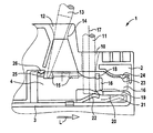
- FIG. 1 is a diagrammatic, partial, simplified, side-elevational view without beads, of a screwless connecting terminal having an insulation-piercing connection that can be displaced in a translational fashion along a conductor rail according to the invention
- FIG. 2 is a front-elevational view of the connecting terminal
- FIG. 3 is a top view of the connecting terminal
- FIGS. 4 and 5 are side-elevational views of functional parts of a specific embodiment of the connecting terminal having a bead on a contact element, with a lateral sliding contacting between the insulation-piercing connection and the conductor rail, in the uncontacted, or contacted, functional position;
- FIG. 6 is an exploded, perspective view of the functional parts of the connecting terminal according to FIGS. 4 and 5;
- FIG. 7 is a side-elevational view of a specific embodiment of the insulation-piercing connection having three beads;
- FIG. 8 is a plan view of a specific embodiment of the insulation-piercing connection having the three beads
- FIG. 9 is a perspective view of the insulation-piercing connection according to FIGS. 7 and 8;
- FIG. 10 is a side-elevational view of the insulation-piercing connection from the same side as is shown in FIG. 7;
- FIG. 11 is a plan view of a front end face of the insulation-piercing connection according to FIG. 10;
- FIG. 12 is a sectional view taken along the line XII—XII in FIG. 10;
- FIG. 13 is a sectional view taken along the line XIII—XIII in FIG. 10;
- FIG. 14 is a top plan view of a rear end face of the insulation-piercing connection according to FIG. 10 .
- FIGS. 1-3 there is shown a simplified view of a screwless connecting terminal 1 in a side view, front view, and top view, for the explanation of functional parts.
- the connecting terminal 1 shown in sections, is preferably realized as what is known as a modular terminal, and for this purpose includes a terminal housing 2 , of which only what is known as a shell, provided with inner contours, is shown.
- the connecting terminal 1 additionally includes, inside the terminal housing 2 , a conductor rail 3 disposed in a stationary fashion, and an insulation-piercing connection 4 situated in a movable fashion thereon.
- the insulation-piercing connection 4 is fashioned in the shape of a U (FIG. 2 ), and has on its clamp limbs 5 , 6 , which are bent towards one another at the free ends, knife-type cutting edges 7 or 8 , between which a cutting and guide slot 9 is formed for the insulation-cutting contacting of a conductor 11 , which is introduced into the terminal housing 2 through a housing lead-through 10 (FIG. 1 ).
- an additional feed-through opening 12 is provided in the terminal housing 2 in front of the feed-through opening 10 , via which additional opening an actuating tool 13 , for example a screwdriver 13 , can be introduced into the terminal housing 2 .
- the feed-through opening 12 is realized as a funnel-shaped housing shaft 12 , which tapers in conical fashion to form a constriction 14 of the funnel-shaped housing shaft 12 , and from there broadens, again in conical fashion, in the direction towards the insulation-piercing connection 4 .
- a dovetail-shaped contact cavity 15 made in the insulation-piercing connection 4 in a region of the cutting edges 7 , 8 thereof, is aligned with the funnel-shaped housing shaft 12 .
- the actuating tool 13 engages in the contact cavity 15 in order to displace the insulation-piercing connection 4 relative to the stationary conductor rail 3 , from the position shown into the position indicated in broken lines.
- the actuating tool 13 is supported in the manner of a lever on a narrowing or constriction 14 .
- the conductor 11 introduced into the terminal housing 2 , is fixed in its position and is held immovable.
- the wall of housing lead-through 10 is used, and on the other hand a support of the conductor 11 in a region between the conductor rail 3 and cutting edges 7 , 8 of the insulation-piercing connection 4 is used.
- guide clips 16 (of which only one is visible), extending in the direction of the housing lead-through 10 , are integrally formed thereon.
- the guide clips 16 flank a conductor end of the conductor 11 , and thus form the lateral support for it.
- An additional backwards support inside the terminal housing 2 in the rail longitudinal direction L behind the housing lead-through 10 , forms a free end 18 , positioned parallel to direction of introduction of the conductor 11 , of an inwardly bent conductor rail segment 19 .
- a sliding contact chamber 21 is formed underneath an underside 20 of conductor rail segment 19 .
- a sliding clip 22 that is integrally formed on the underside, situated opposite the cutting edges 7 and 8 , of the insulation-piercing connection 4 , and is positioned in a direction of the feed-through opening 10 .
- the sliding clip 22 is situated adjacent to the underside of the bent-in conductor rail segment 19 . In this way, the electrically conductive connection is produced between the insulation-piercing connection 4 and the conductor rail 3 .
- the insulation-piercing connection 4 is locked in this contacting functional position, in which the cutting edges 7 and 8 penetrate the insulation of the conductor 11 and contact the leads thereof.
- a locking groove 23 is provided on the clamp clip 16 , or on each such clip, into which groove a locking hook 24 , integrally formed on the inner contour of the terminal housing 2 , snaps in a resilient, spring-loaded fashion.
- a further snap connection, which locks into place in the shown open position, is also provided on the backside, situated opposite guide clips 16 , of the insulation-piercing connection 4 .
- a locking groove 25 is in turn formed therein, into which a likewise springy locking hook 26 snaps in.
- FIGS. 4 and 5 A first specific embodiment of the screwless connecting terminal 1 according to the invention is shown in FIGS. 4 and 5 in the uncontacted or contacted functional position. Only the functional element of the connecting terminal 1 , formed in turn from the conductor rail 3 and the insulation-piercing connection 4 , is shown, for the insulation-piercing contacting of the conductor 11 .
- the insulation-piercing connection 4 is displaced in a translational fashion in the direction L of the conductor rail 3 , and thus in the direction towards the conductor 11 , which is held in immovable and stationary fashion inside the terminal housing 2 .
- the insulation-piercing contacting takes place as a result of a cutting of a conductor insulation 11 a by the cutting edges 7 and 8 of the insulation-piercing connection 4 , until the contacting thereof with conductor leads 11 b takes place.
- a bead 35 formed into the clamp limb 5 , can be seen clearly in FIG. 4 and FIG. 5 .
- the bead 35 reinforces the clamp limb 5 , which can be seen clearly in particular in FIG. 5, precisely in the region that coincides with the electrical conductor 11 in its final contacting position, shown in FIG. 5 .
- the electrically conductive connection between the insulation-piercing connection 4 and the conductor rail 3 takes place by a lateral sliding contact.
- This is realized through sliding clips 27 that are integrally formed on the insulation-piercing connection 4 .
- the clips 27 being situated adjacent to opposed side edges 28 of the conductor rail 3 .
- the inwardly curved sliding clips 27 of the conductor rail 4 enclose between them a conductor rail region 29 , which is constructed in waisted fashion and is formed by recesses 30 on both sides of the conductor rail 3 .
- the recesses 30 thus simultaneously form stop edges 31 and 32 in the contacting, or uncontacting, functional position of the insulation-piercing connection 4 , which can be translationally displaced on the conductor rail 3 .
- FIG. 7 shows, as do FIGS. 8 and 9, a preferred specific embodiment of the insulation cutting connection 4 , having three beads 35 situated alongside one another in the direction of a center longitudinal axis 37 .
- the beads 35 are formed into the clamp limbs 5 , 6 in a circumferential fashion, and thus form U-shaped reinforcing beads.
- the overall region of the insulation-piercing connection 4 is reinforced that comes into contact with electrical conductor 11 of the insulation-piercing contacting.
- the figures also illustrate the possibility of providing additional beads 36 in other regions on the insulation-piercing connection 4 , for the reinforcement of additional regions of insulation-piercing connection 4 .
- the beads 35 result in an increase in the spring force of the U-shaped insulation-piercing connection 4 , with the result that the clamp limbs 5 , 6 , or the cutting edges 7 , 8 , are not spread as far apart by the electrical conductor 11 as is the case in a specific embodiment having the same wall thickness without the beads 35 .
- FIG. 10 shows the same side view of the insulation-piercing connection 4 as does FIG. 7, but with two sections XII—XII, XIII—XIII.
- the beads 35 tapering in the direction towards the cutting edges 7 , 8 , and the concomitant decreasing effective wall thickness W S of the insulation-piercing connection 4 , are described.
- FIG. 11 shows a top view of the front end face of the insulation-piercing connection 4 .
- the clamp limbs 5 , 6 are shown in a partially transparent fashion.
- the effective wall thickness W S of the insulation-piercing connection 4 can be depicted.
- the effective wall thickness W S at the bead 35 in the region of a base 38 of the U of insulation-piercing connection 4 is shown.
- the effective wall thickness in the upper region of clamp limbs 5 , 6 is significantly less, because a bead depth T S decreases as it moves upward.
- FIG. 12 shows a sectional view along the line XII—XII in FIG. 10 .
- the effective wall thickness W S is shown, here in the region of the bead 36 . Because the bead 36 also tapers towards the top, the effective wall thickness W S in turn correspondingly decreases.
- FIG. 13 shows a sectional view taken along the line XIII—XIII in FIG. 10 .
- each of the beads 35 runs out upward in the direction towards the cutting edges 7 , 8 ; i.e., bead depth T S decreases from the base 38 of the U of insulation-piercing connection 4 towards the cutting edges 7 , 8 .
- the bead 35 stands out strongly in the vicinity of the base 38 of the U, and is beveled upward in the direction towards the cutting edges 7 , 8 , to the outer wall of clamp limbs 5 , 6 .
- the effective wall thickness W S of the insulation-piercing connection 4 decreases from the base 38 of the U upwards in the direction towards the cutting edges 7 , 8 .
- the effective wall thickness W S thus tapers from the base 38 of the U of insulation-piercing connection 4 in the direction towards the cutting edges 7 , 8 .
- FIG. 14 shows a top view of the rear end face of the insulation-piercing connection 4 .
- the bead depth T S of the bead 36 and thus also the effective wall thickness (see FIG. 12 ), decreases as it moves upward.
Landscapes
- Connections Arranged To Contact A Plurality Of Conductors (AREA)
- Multi-Conductor Connections (AREA)
- Discharge Heating (AREA)
- Coupling Device And Connection With Printed Circuit (AREA)
- Fixed Capacitors And Capacitor Manufacturing Machines (AREA)
- Adhesive Tapes (AREA)
- Electrochromic Elements, Electrophoresis, Or Variable Reflection Or Absorption Elements (AREA)
- Liquid Crystal Substances (AREA)
Applications Claiming Priority (3)
| Application Number | Priority Date | Filing Date | Title |
|---|---|---|---|
| DE10119652A DE10119652A1 (de) | 2001-04-20 | 2001-04-20 | Schraubenlose Anschlussklemme |
| DE10119652 | 2001-04-20 | ||
| DE10119652.0 | 2001-04-20 |
Publications (2)
| Publication Number | Publication Date |
|---|---|
| US20020155749A1 US20020155749A1 (en) | 2002-10-24 |
| US6796830B2 true US6796830B2 (en) | 2004-09-28 |
Family
ID=7682270
Family Applications (1)
| Application Number | Title | Priority Date | Filing Date |
|---|---|---|---|
| US10/127,668 Expired - Fee Related US6796830B2 (en) | 2001-04-20 | 2002-04-22 | Screwless connecting terminal |
Country Status (8)
| Country | Link |
|---|---|
| US (1) | US6796830B2 (de) |
| EP (1) | EP1251589B1 (de) |
| AT (1) | ATE259103T1 (de) |
| BR (1) | BR0201361A (de) |
| CA (1) | CA2382681C (de) |
| DE (2) | DE10119652A1 (de) |
| DK (1) | DK1251589T3 (de) |
| TR (1) | TR200400485T4 (de) |
Cited By (10)
| Publication number | Priority date | Publication date | Assignee | Title |
|---|---|---|---|---|
| US20070207662A1 (en) * | 2006-03-02 | 2007-09-06 | Emilio Germani | Multipolar electrical connector with spring contacts |
| US7354296B1 (en) | 2006-09-21 | 2008-04-08 | Hubbell Incorporated | Contact termination member for an electrical receptacle |
| US20090088019A1 (en) * | 2007-09-27 | 2009-04-02 | Tuerkekoele Muhammet Ali | Insulation-displacement connection |
| US20100009567A1 (en) * | 2008-07-11 | 2010-01-14 | Reichle & De-Massari Ag | Insulation displacement contact and contacting device |
| US20140113509A1 (en) * | 2011-06-08 | 2014-04-24 | Maria Cristina Moret Codina | Electrical contact |
| US9136518B2 (en) | 2009-12-04 | 2015-09-15 | Brusa Elektronik Ag | Terminal for accumulator cells |
| US9184515B1 (en) * | 2012-09-28 | 2015-11-10 | Anthony Freakes | Terminal blocks for printed circuit boards |
| US9819121B2 (en) * | 2016-03-07 | 2017-11-14 | Omron Corporation | Screwless terminal block |
| US10074917B1 (en) * | 2017-02-28 | 2018-09-11 | Omron Corporation | Terminal block |
| US10944188B2 (en) * | 2018-03-14 | 2021-03-09 | Omron Corporation | Terminal block |
Families Citing this family (1)
| Publication number | Priority date | Publication date | Assignee | Title |
|---|---|---|---|---|
| FR3113544B1 (fr) * | 2020-08-20 | 2022-09-02 | Berker Gmbh & Co Kg | Borne de connexion auto-dénudante d’un conducteur électrique isolé |
Citations (13)
| Publication number | Priority date | Publication date | Assignee | Title |
|---|---|---|---|---|
| US3634818A (en) * | 1968-09-26 | 1972-01-11 | Molex Inc | Female electrical terminal |
| EP0063206A2 (de) | 1981-04-16 | 1982-10-27 | Grote & Hartmann GmbH & Co. KG | Klemmkontakt |
| US5620332A (en) * | 1994-08-10 | 1997-04-15 | Krone Aktiengesellschaft | Terminal element |
| US5624273A (en) | 1995-04-21 | 1997-04-29 | The Whitaker Corporation | Insulation displacement contact with strain relief |
| JPH10134861A (ja) | 1996-10-30 | 1998-05-22 | Fujikura Ltd | フラットケーブル用圧接コネクタ及びそれに用いられる圧接端子 |
| EP0851534A2 (de) | 1996-12-26 | 1998-07-01 | Yazaki Corporation | Druckanschlussklemme |
| US5816843A (en) * | 1995-10-30 | 1998-10-06 | Wago Verwaltungsgesellschaft Mbh | Electrical front wiring clamp |
| US5879181A (en) * | 1996-08-06 | 1999-03-09 | Yazaki Corporation | Insulation piercing terminal |
| US6033255A (en) * | 1997-02-19 | 2000-03-07 | Yazaki Corporation | Press-connecting terminal |
| US6120316A (en) * | 1996-04-13 | 2000-09-19 | Richard Hirschmann Gmbh & Co. | Cable plug connector |
| WO2000070714A1 (de) | 1999-05-14 | 2000-11-23 | Wieland Electric Gmbh | Schraubenlose anschlussklemme |
| US6361352B2 (en) * | 1998-08-07 | 2002-03-26 | Entrelec S.A. | Insulation-displacement connector |
| US6468103B1 (en) * | 2001-04-23 | 2002-10-22 | Corning Cable Systems Llc | Insulation displacement connector for parallel wire insertion |
Family Cites Families (1)
| Publication number | Priority date | Publication date | Assignee | Title |
|---|---|---|---|---|
| DE4417139C2 (de) * | 1994-05-17 | 1996-04-18 | Rudolf Wiesmann | Vorrichtung und Anlage zur Desinfektion von strömenden Flüssigkeiten sowie Verwendung derselben |
-
2001
- 2001-04-20 DE DE10119652A patent/DE10119652A1/de not_active Ceased
-
2002
- 2002-04-17 TR TR2004/00485T patent/TR200400485T4/xx unknown
- 2002-04-17 AT AT02008645T patent/ATE259103T1/de not_active IP Right Cessation
- 2002-04-17 DE DE50200236T patent/DE50200236D1/de not_active Expired - Lifetime
- 2002-04-17 DK DK02008645T patent/DK1251589T3/da active
- 2002-04-17 EP EP02008645A patent/EP1251589B1/de not_active Expired - Lifetime
- 2002-04-19 CA CA002382681A patent/CA2382681C/en not_active Expired - Fee Related
- 2002-04-22 BR BR0201361-4A patent/BR0201361A/pt not_active Application Discontinuation
- 2002-04-22 US US10/127,668 patent/US6796830B2/en not_active Expired - Fee Related
Patent Citations (14)
| Publication number | Priority date | Publication date | Assignee | Title |
|---|---|---|---|---|
| US3634818A (en) * | 1968-09-26 | 1972-01-11 | Molex Inc | Female electrical terminal |
| EP0063206A2 (de) | 1981-04-16 | 1982-10-27 | Grote & Hartmann GmbH & Co. KG | Klemmkontakt |
| US5620332A (en) * | 1994-08-10 | 1997-04-15 | Krone Aktiengesellschaft | Terminal element |
| US5624273A (en) | 1995-04-21 | 1997-04-29 | The Whitaker Corporation | Insulation displacement contact with strain relief |
| US5816843A (en) * | 1995-10-30 | 1998-10-06 | Wago Verwaltungsgesellschaft Mbh | Electrical front wiring clamp |
| US6120316A (en) * | 1996-04-13 | 2000-09-19 | Richard Hirschmann Gmbh & Co. | Cable plug connector |
| US5879181A (en) * | 1996-08-06 | 1999-03-09 | Yazaki Corporation | Insulation piercing terminal |
| JPH10134861A (ja) | 1996-10-30 | 1998-05-22 | Fujikura Ltd | フラットケーブル用圧接コネクタ及びそれに用いられる圧接端子 |
| EP0851534A2 (de) | 1996-12-26 | 1998-07-01 | Yazaki Corporation | Druckanschlussklemme |
| US6033255A (en) * | 1997-02-19 | 2000-03-07 | Yazaki Corporation | Press-connecting terminal |
| US6361352B2 (en) * | 1998-08-07 | 2002-03-26 | Entrelec S.A. | Insulation-displacement connector |
| WO2000070714A1 (de) | 1999-05-14 | 2000-11-23 | Wieland Electric Gmbh | Schraubenlose anschlussklemme |
| US6527580B1 (en) * | 1999-05-14 | 2003-03-04 | Wieland Electric Gmbh | Screwless terminal |
| US6468103B1 (en) * | 2001-04-23 | 2002-10-22 | Corning Cable Systems Llc | Insulation displacement connector for parallel wire insertion |
Non-Patent Citations (4)
| Title |
|---|
| Alfred B�ge: "Formeln und Tabellen zur Mechanik und Festigkeitslehre" [formulas and tables for mechanics and strength], Viewegs Fachb�cher der Technik, p. 29. |
| Alfred Böge: "Formeln und Tabellen zur Mechanik und Festigkeitslehre" [formulas and tables for mechanics and strength], Viewegs Fachbücher der Technik, p. 29. |
| Dubbel: "Taschenbuch f�r den Maschinenbau" [pocket book for mechanical engineering], Springer Verlag, Berlin, 1974, vol. 1, pp. 378-379, 426-427. |
| Dubbel: "Taschenbuch für den Maschinenbau" [pocket book for mechanical engineering], Springer Verlag, Berlin, 1974, vol. 1, pp. 378-379, 426-427. |
Cited By (15)
| Publication number | Priority date | Publication date | Assignee | Title |
|---|---|---|---|---|
| US20070207662A1 (en) * | 2006-03-02 | 2007-09-06 | Emilio Germani | Multipolar electrical connector with spring contacts |
| US7438587B2 (en) * | 2006-03-02 | 2008-10-21 | Industria Lombarda Materiale Elettrico I.L.M.E. S.P.A. | Multipolar electrical connector with spring contacts |
| US7354296B1 (en) | 2006-09-21 | 2008-04-08 | Hubbell Incorporated | Contact termination member for an electrical receptacle |
| US20080085626A1 (en) * | 2006-09-21 | 2008-04-10 | Hubbell Incorporated | Contact termination member for an electrical receptacle |
| US7704093B2 (en) * | 2007-09-27 | 2010-04-27 | Wago Verwaltungsgesellschaft Mbh | Insulation-displacement connection |
| US20090088019A1 (en) * | 2007-09-27 | 2009-04-02 | Tuerkekoele Muhammet Ali | Insulation-displacement connection |
| US20100009567A1 (en) * | 2008-07-11 | 2010-01-14 | Reichle & De-Massari Ag | Insulation displacement contact and contacting device |
| US7857655B2 (en) | 2008-07-11 | 2010-12-28 | Reichle & De-Massari Ag | Insulation displacement contact and contacting device |
| US9136518B2 (en) | 2009-12-04 | 2015-09-15 | Brusa Elektronik Ag | Terminal for accumulator cells |
| US20140113509A1 (en) * | 2011-06-08 | 2014-04-24 | Maria Cristina Moret Codina | Electrical contact |
| US9343826B2 (en) * | 2011-06-08 | 2016-05-17 | Simon, S.A.U. | Electrical contact |
| US9184515B1 (en) * | 2012-09-28 | 2015-11-10 | Anthony Freakes | Terminal blocks for printed circuit boards |
| US9819121B2 (en) * | 2016-03-07 | 2017-11-14 | Omron Corporation | Screwless terminal block |
| US10074917B1 (en) * | 2017-02-28 | 2018-09-11 | Omron Corporation | Terminal block |
| US10944188B2 (en) * | 2018-03-14 | 2021-03-09 | Omron Corporation | Terminal block |
Also Published As
| Publication number | Publication date |
|---|---|
| CA2382681C (en) | 2007-07-03 |
| BR0201361A (pt) | 2003-06-10 |
| CA2382681A1 (en) | 2002-10-20 |
| TR200400485T4 (tr) | 2004-04-21 |
| EP1251589A1 (de) | 2002-10-23 |
| EP1251589B1 (de) | 2004-02-04 |
| DE10119652A1 (de) | 2002-11-14 |
| ATE259103T1 (de) | 2004-02-15 |
| DE50200236D1 (de) | 2004-03-11 |
| US20020155749A1 (en) | 2002-10-24 |
| DK1251589T3 (da) | 2004-06-07 |
Similar Documents
| Publication | Publication Date | Title |
|---|---|---|
| US4340270A (en) | Electrical terminal unit | |
| US10658766B2 (en) | Spring terminal for a conductor | |
| FI64480B (fi) | Elektrisk stickanslutningsklaemma | |
| US6796830B2 (en) | Screwless connecting terminal | |
| US3596229A (en) | Electrical connector | |
| CN101064383B (zh) | 电气连接器 | |
| US6270383B1 (en) | Resilient terminal including conductor centering means | |
| US5005104A (en) | Clip-connected terminal conductor assembly | |
| KR20090048471A (ko) | 절연 변위 커넥터 | |
| CA1286741C (en) | Cutting/clamping sleeve contact | |
| US6099347A (en) | Low profile shunt connector | |
| US4715824A (en) | Connector for interconnecting cable to a printed circuit board | |
| KR970700383A (ko) | 절연변위형의 전기 접속 수단을 포함하는 전자 메모리 카드용 전기 접속기(electrical connector for an electronic memory card, including electrical connection means of the insulation-displacement type) | |
| US4846722A (en) | Arrangement for electrical connections and in particular a junction block | |
| HK1000395B (en) | Connector for interconnecting a cable to a printed circuit board or a contact pinholder | |
| US4346955A (en) | Self-stripping terminal for an electrical connector | |
| US5647761A (en) | Lamp bulb holder and a method of assembling a lamp bulb holder | |
| JPH0626150B2 (ja) | 電線自動露出コネクタ | |
| FI95633C (fi) | Ruuviton kytkentäliitos ja sen valmistusmenetelmä | |
| JP3340325B2 (ja) | 複数段にケーブル列を配する電気コネクタ | |
| CN113629413A (zh) | 接线端子 | |
| CN120089977A (zh) | 弹簧力夹紧连接件和接线端子 | |
| US4735586A (en) | Conductor connector | |
| US7025622B2 (en) | Contact element terminal with a contact element and method for contacting a conductor with a contact element | |
| GB2321790A (en) | A cam operated clamping terminal |
Legal Events
| Date | Code | Title | Description |
|---|---|---|---|
| AS | Assignment |
Owner name: WIELAND ELECTRIC GMBH, GERMANY Free format text: ASSIGNMENT OF ASSIGNORS INTEREST;ASSIGNORS:SUSS, CHRISTIAN;UNGERMANN, HEINZ;REEL/FRAME:015721/0229 Effective date: 20020516 |
|
| FPAY | Fee payment |
Year of fee payment: 4 |
|
| REMI | Maintenance fee reminder mailed | ||
| LAPS | Lapse for failure to pay maintenance fees | ||
| STCH | Information on status: patent discontinuation |
Free format text: PATENT EXPIRED DUE TO NONPAYMENT OF MAINTENANCE FEES UNDER 37 CFR 1.362 |
|
| FP | Lapsed due to failure to pay maintenance fee |
Effective date: 20120928 |