US6831456B2 - Angle sensor and method of increasing the anisotropic field strength of a sensor unit of an angle sensor - Google Patents
Angle sensor and method of increasing the anisotropic field strength of a sensor unit of an angle sensor Download PDFInfo
- Publication number
- US6831456B2 US6831456B2 US10/120,681 US12068102A US6831456B2 US 6831456 B2 US6831456 B2 US 6831456B2 US 12068102 A US12068102 A US 12068102A US 6831456 B2 US6831456 B2 US 6831456B2
- Authority
- US
- United States
- Prior art keywords
- angle sensor
- magnetoresistive
- sensor
- field strength
- anisotropic
- Prior art date
- Legal status (The legal status is an assumption and is not a legal conclusion. Google has not performed a legal analysis and makes no representation as to the accuracy of the status listed.)
- Expired - Fee Related
Links
- 238000000034 method Methods 0.000 title claims abstract description 14
- 239000000463 material Substances 0.000 claims description 7
- 239000010409 thin film Substances 0.000 claims description 6
- 229910003266 NiCo Inorganic materials 0.000 claims description 5
- 230000002269 spontaneous effect Effects 0.000 claims description 4
- 229910019236 CoFeB Inorganic materials 0.000 claims description 3
- 229910001030 Iron–nickel alloy Inorganic materials 0.000 claims description 3
- 230000005389 magnetism Effects 0.000 claims description 3
- 238000005259 measurement Methods 0.000 description 8
- 238000012937 correction Methods 0.000 description 2
- 230000001419 dependent effect Effects 0.000 description 2
- 238000004519 manufacturing process Methods 0.000 description 2
- 238000002485 combustion reaction Methods 0.000 description 1
- 238000013461 design Methods 0.000 description 1
- 238000001514 detection method Methods 0.000 description 1
- 230000000694 effects Effects 0.000 description 1
- 238000011156 evaluation Methods 0.000 description 1
- 230000007774 longterm Effects 0.000 description 1
- 238000012986 modification Methods 0.000 description 1
- 230000004048 modification Effects 0.000 description 1
- 230000002123 temporal effect Effects 0.000 description 1
Images


Classifications
-
- G—PHYSICS
- G01—MEASURING; TESTING
- G01D—MEASURING NOT SPECIALLY ADAPTED FOR A SPECIFIC VARIABLE; ARRANGEMENTS FOR MEASURING TWO OR MORE VARIABLES NOT COVERED IN A SINGLE OTHER SUBCLASS; TARIFF METERING APPARATUS; MEASURING OR TESTING NOT OTHERWISE PROVIDED FOR
- G01D5/00—Mechanical means for transferring the output of a sensing member; Means for converting the output of a sensing member to another variable where the form or nature of the sensing member does not constrain the means for converting; Transducers not specially adapted for a specific variable
- G01D5/12—Mechanical means for transferring the output of a sensing member; Means for converting the output of a sensing member to another variable where the form or nature of the sensing member does not constrain the means for converting; Transducers not specially adapted for a specific variable using electric or magnetic means
- G01D5/14—Mechanical means for transferring the output of a sensing member; Means for converting the output of a sensing member to another variable where the form or nature of the sensing member does not constrain the means for converting; Transducers not specially adapted for a specific variable using electric or magnetic means influencing the magnitude of a current or voltage
- G01D5/142—Mechanical means for transferring the output of a sensing member; Means for converting the output of a sensing member to another variable where the form or nature of the sensing member does not constrain the means for converting; Transducers not specially adapted for a specific variable using electric or magnetic means influencing the magnitude of a current or voltage using Hall-effect devices
- G01D5/145—Mechanical means for transferring the output of a sensing member; Means for converting the output of a sensing member to another variable where the form or nature of the sensing member does not constrain the means for converting; Transducers not specially adapted for a specific variable using electric or magnetic means influencing the magnitude of a current or voltage using Hall-effect devices influenced by the relative movement between the Hall device and magnetic fields
-
- G—PHYSICS
- G01—MEASURING; TESTING
- G01B—MEASURING LENGTH, THICKNESS OR SIMILAR LINEAR DIMENSIONS; MEASURING ANGLES; MEASURING AREAS; MEASURING IRREGULARITIES OF SURFACES OR CONTOURS
- G01B7/00—Measuring arrangements characterised by the use of electric or magnetic techniques
- G01B7/30—Measuring arrangements characterised by the use of electric or magnetic techniques for measuring angles or tapers; for testing the alignment of axes
Definitions
- the invention relates to an angle sensor comprising at least two angle-offset anisotropic magnetoresistive sensor units (AMR sensor unit) comprising anisotropic magnetoresistive elements (AMR elements).
- AMR sensor unit angle-offset anisotropic magnetoresistive sensor units
- AMR elements anisotropic magnetoresistive elements
- angle sensors When such angle sensors are used in a magnetic field which is clearly stronger than its anisotropic field strength, which is the typical field of use of the known AMR angle sensors, the sensor is driven into saturation so that it generates a characteristic with a sin (2 ⁇ ) periodical variation.
- the sin (2 ⁇ ) periodical characteristic has the consequence that the angle sensor can only perform 180° angle measurements because, due to the periodicity, it is not possible to distinguish between 0° and 180°.
- GMR sensors giant magnetoresistive sensors
- technological systems with a plurality of sensors and toothed wheels are required, which leads either to a highly complex manufacture and an attendant increase of costs, or to the fact that the angle sensors can no longer operate without contact.
- long-term stability of GMR sensors is currently not quite clear.
- an angle sensor which comprises at least two angle-offset anisotropic magnetoresistive sensor units comprising anisotropic magnetoresistive elements, in which the angle sensor comprises at least a device for increasing the anisotropic field strength of the sensor units, and by an angle sensor in which the magnetoresistive element comprises magnetoresistive layers, particularly magnetoresistive strips which have a substantially hyperboloid or asteroidal shape.
- the object is further solved by a method of increasing the anisotropic field strength of a sensor unit of an angle sensor comprising magnetoresistive elements, in which a magnetic supporting field present in the preferred direction of the magnetoresistive elements is generated, and by a method in which the magnetoresistive elements are built up of magnetoresistive layers, particularly magnetoresistive strips, in which the magnetoresistive layers are given a substantially hyperboloid or asteroidal shape.
- the angle sensor comprises at least a device for increasing the anisotropic field strength of the sensor units used in the angle sensor.
- An angle sensor according to the invention utilizes the fact that the characteristic of an AMR angle sensor has a periodicity of sin ( ⁇ ) when the sensor is driven at field strengths below the anisotropic field strength. At such a periodicity, a 360° measurement is also possible.
- an AMR angle sensor Due to the use of an angle sensor with a device for increasing the anisotropic field strength of the sensor units, the anisotropic field strength can therefore be increased so far that even the high field strengths occurring particularly in automobiles but also in other areas are below the anisotropic field strength of the AMR angle sensor. Consequently, an AMR angle sensor is provided in a simple and low-cost way which renders a 360° measurement possible in a low-cost and contactless way, even at very high field strengths.
- the device for increasing the anisotropic field strength of the sensor unit impresses a supporting field in a preferred direction of the magnetoresistive elements, which field increases the anisotropic field strength of the sensor units and the magnetoresistive elements (MR elements).
- MR elements magnetoresistive elements
- Typical field strengths for a supporting field in the preferred direction are between 1 and 10 kA/m, preferably between 1 and 6 kA/m, in which conventional magnetic field strengths are at about 4 kA/m.
- the measuring field strengths in which the angle sensor is used are of a similar order of magnitude, but the measuring field strength is preferably slightly smaller than the field strength of the supporting field.
- Typical measuring field strengths are in a range of 3 kA/m but are quite dependent on the fields in which they are used.
- a soft magnetic shield against external interference fields is advantageous.
- the MR elements generally comprise parallel arranged MR strips which are aligned in a preferred direction but may also be formed differently.
- the device for increasing the anisotropic field strength comprises at least a coil arrangement in which at least one external coil per magnetoresistive element is preferably used, which coil substantially completely surrounds the MR element so that, in the core area of the coil, the magnetic field is aligned in the preferred direction of the MR elements.
- another embodiment provides the possibility of using at least one thin-film coil integrated in the layout of each MR element.
- the devices for increasing the anisotropic field strength of the sensor units may be devices which permanently increase the anisotropic field strength such as, for example, the above-mentioned permanent magnet, while the invention also encompasses devices which can increase the anisotropic field strength in a discontinuous and a controlled manner as in, for example, the above-mentioned coil arrangements or in the case of electromagnets.
- the anisotropic field strength may be controlled temporally and as regards its extent, while the invention encompasses both a periodical and also a non-periodical increase of the anisotropic field strength in the case of temporal control.
- a further possibility for the device for increasing the anisotropic field strength is a hard magnetic layer which is provided on the MR elements. This device is a device which permanently increases the anisotropic field strength.
- the at least two angle-offset anisotropic magnetoresistive sensor units are tilted by an angle of 90°, which provides the possibility of a 360° measurement.
- a tilt of, for example, about 45° is possible and that the angle sensor according to the invention can be designed with the device for increasing the anisotropic field strength of the sensor units in dependence upon their field of use and in such a way that it only measures a reduced angle range of, for example, 180°.
- the angle sensor according to the invention is therefore not limited to a 360° AMR angle sensor, although this is a preferred field of use and the advantages of the angle sensor according to the invention become particularly manifest in such a measurement.
- the MR elements in the sensor units preferably comprise MR layers, particularly MR strips having a predetermined length (l), width (b) and thickness (d).
- MR layers particularly MR strips having a predetermined length (l), width (b) and thickness (d).
- l length
- b width
- d thickness
- At least one of the MR layers rectangularly, hyperbolically and/or asteroidally, so that an increase of the anisotropic field strength of the sensor element is also achieved.
- the MR layers consist of a material having a high intrinsic material anisotropy.
- the angle sensor further comprises means for applying magnetic reversal coils, which means preferably comprise at least one coil arrangement.
- the external coils, or the internal thin-film coils integrated in the layout of the MR elements described above are also suitable as coil arrangements.
- the magnetic reversal coils are at least used in a controlled manner at given points, where “flipping” of the characteristic curve is compensated, which occurs when the angle sensor is used in the range of anisotropic field strengths and moves in a limit range in which it generates characteristics with a sin (2 ⁇ ) periodicity and characteristics with a sin ( ⁇ ) periodicity, which leads to a spontaneous magnetic reversal in MR sensor elements.
- the angle sensor according to the invention therefore provides the possibility of a 360° angle detection in that the anisotropic field strength is increased to such an extent that the field strength in which the sensor is used is clearly below the anisotropic field strength of the sensor, so that a characteristic with a sin ( ⁇ ) periodicity is generated, or in that the spontaneous reversal of magnetism (flipping of the characteristic curve) occurring in the limit range between the sin (2 ⁇ ) and the sin ( ⁇ ) periodicity is clearly defined by magnetic reversal coils so that a 360° signal is obtained after signal evaluation.
- a further embodiment of the angle sensor comprises a subsequently arranged or integrated signal electronic circuit which generates a post-correction of the output signals, particularly a correction which becomes necessary because of the above-described flipping of the characteristic curve so that also in this case a 360° signal is obtained, even when the means for applying magnetic reversal coils are not provided and the anisotropic field strength of the sensor unit is not clearly above the field strength in which the angle sensor is used, so that also this signal electronic circuit is an independent inventive aspect.
- the invention further relates to a method of increasing the anisotropic field strength of a sensor unit of an angle sensor comprising magnetoresistive elements having a preferred direction, in which in accordance with the inventive method a magnetic supporting field in the preferred direction is generated.
- An AMR angle sensor can thereby be provided in a simple manner, which renders a 360° measurement possible, also at high field strengths.
- the supporting field may be applied both permanently and discontinuously, in which the above-mentioned devices and methods can be used for generating the supporting field. It is particularly preferred that the supporting field is generated by means of a coil arrangement or a magnet, while it is further possible to generate the supporting field by means of a hard magnetic layer which is provided on or beside the MR elements.
- FIG. 1 shows a principal structure of an embodiment of an angle sensor according to the invention
- FIG. 2 shows an embodiment of a sensor whose principal structure is shown in FIG. 1;
- FIG. 3 a is a plan view of an embodiment of an MR element with MR strips and an external coil according to the invention
- FIG. 3 b is a side elevation of the MR element shown in FIG. 3 a;
- FIG. 4 a is a plan view of an embodiment of an MR element with internal coils according to the invention.
- FIG. 4 b is an enlarged elevational view of the range denoted by b in FIG. 4 a;
- FIG. 5 a is a plan view of an embodiment of an MR element with an external magnet according to the invention.
- FIG. 5 b is a side elevation of the embodiment of the MR element shown in FIG. 5 a;
- FIG. 6 a is a plan view of an embodiment of an MR element with a hard magnetic layer according to the invention.
- FIG. 6 b is a side elevation of the MR element shown in FIG. 6 a;
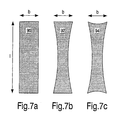
- FIGS. 7 a,b,c show possible geometrical shapes of MR strips according to the invention.
- FIG. 1 shows diagrammatically the principal structure of a 360° AMR sensor 20 as a possible embodiment of a sensor according to the invention.
- the sensor comprises two DC separated sensor units 40 , 42 one of which is aligned parallel to the chip sides (cos bridge) and another one is arranged at an angle of 90° thereto (sin bridge).
- the bridges or sensor units 40 , 42 comprise four anisotropic magnetoresistive elements (MR elements) 60 and 62 , respectively.
- the angle sensor 20 has terminals 22 , 24 , 26 , 28 , 30 , 32 , 34 , 36 .
- FIG. 2 A possible embodiment of an AMR sensor shown in FIG. 1 is shown diagrammatically in FIG. 2 .
- the angle sensor 20 comprises the two sensor units ( 40 , 42 see FIG. 1 ), in which each sensor unit comprises MR elements 60 and 62 , respectively.
- the MR elements 60 , 62 of the two sensor units comprise anisotropic magnetoresistive strips (MR strips) 80 which are arranged always parallel to each other within each MR element 60 , 62 .
- MR strips anisotropic magnetoresistive strips
- Embodiments of MR elements according to the invention which may be used in angle sensors and are shown in FIGS. 1 and 2, will now be described with reference to the following Figures.
- FIG. 3 is a plan view of an MR element 64 provided with MR strips 82 .
- a coil 100 which substantially completely surrounds the MR element 64 , is used as a device for increasing the anisotropic field strength of the MR element.
- the shape of the coil 100 is particularly visible in FIG. 3 b in which the MR element 64 can be clearly seen in a cross-section and has a surface on which the MR strips 82 have been provided.
- the coil 100 substantially completely surrounds the MR element 64 .
- coil cross-section is shown rectangularly in this case, it may also assume any other arbitrary geometrical shape, for example, also a circular cross-section.
- the coil 100 generates a substantially homogeneous magnetic field in the core, which field is denoted by the arrow H.
- the magnetic field is aligned substantially parallel to the longitudinal alignment of the MR strips which corresponds to the preferred direction of the MR strips.
- FIG. 4 shows a further embodiment of an MR element according to the invention.
- FIG. 4 a is a plan view of an MR element 66 which, likewise as the element shown in FIG. 3 a , also has longitudinal MR strips 84 .
- internal coils 120 are provided in this embodiment.
- the structure of an internal coil 120 is particularly clear from FIG. 4 b in which the magnetic field H generated by the coil or the coils 120 substantially corresponds to the magnetic field H as is also generated in the embodiment shown in FIG. 3 .
- the coils 120 are thin-film coils integrated in the layout, so that the dimensions of the MR elements with the coils can be clearly reduced with respect to the dimensions of the embodiment shown in FIG. 3 .
- FIG. 5 shows a further embodiment of an MR element according to the invention.
- the MR element 68 is provided on a permanent magnet 140 with a north pole N and a south pole S. Also in this embodiment, the magnet 140 generates a magnetic field H which is aligned in the direction of the MR strips 86 and the preferred direction of the MR element.
- FIG. 5 b is a side elevation of the embodiment shown in FIG. 5 a , in which the structural form and the arrangement of the MR element 68 on the surface of the magnet 140 is clearly visible.
- the embodiment shown in FIG. 5 is more voluminous as compared with the embodiment shown in FIG. 4 but this embodiment can be manufactured at low cost and is very reliable because of the relative insensitivity of the magnet.
- FIG. 6 shows a further embodiment of an MR element according to the invention.
- the MR element 70 is substantially analog to the MR elements shown in FIGS. 3 to 5 , and in this embodiment MR strips 88 are also arranged in the preferred direction of the MR element 70 .
- a hard-magnetic layer 160 is provided on the surface of the MR element 70 and above the MR strips 88 in this embodiment.
- This hard magnetic layer 160 also generates a magnetic field H in the preferred direction, analogously to the embodiments described hereinbefore.
- the MR strips ( 80 , 82 , 84 , 86 , 88 ) are diagrammatically shown as lines only in FIGS. 3 to 6 .
- the geometrical design may however, be varied in accordance with the invention, which is particularly shown in FIG. 7 .
- FIG. 7 a shows an MR strip 90 which is rectangular and has a length l in the preferred direction and a width b.
- FIG. 7 b shows a further possible embodiment of an MR strip 92 which has a hyperboloid shape, whereas the MR strip 94 shown in FIG. 7 c has an asteroidal shape.
- the aspect ratio between length l and width b should be chosen to be as large as possible so as to achieve a high anisotropic field strength, and is in a range between 50 and 200 in the embodiment shown.
- a particularly preferred aspect ratio is about 100.
Landscapes
- Physics & Mathematics (AREA)
- General Physics & Mathematics (AREA)
- Measuring Magnetic Variables (AREA)
- Hall/Mr Elements (AREA)
- Measurement Of Length, Angles, Or The Like Using Electric Or Magnetic Means (AREA)
- Transmission And Conversion Of Sensor Element Output (AREA)
Applications Claiming Priority (3)
| Application Number | Priority Date | Filing Date | Title |
|---|---|---|---|
| DE10118650.9 | 2001-04-14 | ||
| DE10118650 | 2001-04-14 | ||
| DE10118650A DE10118650A1 (de) | 2001-04-14 | 2001-04-14 | Winkelsensor sowie Verfahren zum Erhöhen der Anisotropiefeldstärke einer Sensoreinheit eines Winkelsensors |
Publications (2)
| Publication Number | Publication Date |
|---|---|
| US20020149358A1 US20020149358A1 (en) | 2002-10-17 |
| US6831456B2 true US6831456B2 (en) | 2004-12-14 |
Family
ID=7681626
Family Applications (1)
| Application Number | Title | Priority Date | Filing Date |
|---|---|---|---|
| US10/120,681 Expired - Fee Related US6831456B2 (en) | 2001-04-14 | 2002-04-11 | Angle sensor and method of increasing the anisotropic field strength of a sensor unit of an angle sensor |
Country Status (4)
| Country | Link |
|---|---|
| US (1) | US6831456B2 (de) |
| EP (1) | EP1249686A3 (de) |
| JP (1) | JP2003004480A (de) |
| DE (1) | DE10118650A1 (de) |
Cited By (11)
| Publication number | Priority date | Publication date | Assignee | Title |
|---|---|---|---|---|
| US20050127905A1 (en) * | 2003-12-03 | 2005-06-16 | Weston Aerospace Limited | Eddy current sensors |
| US20060097721A1 (en) * | 2002-11-29 | 2006-05-11 | Yamaha Corporation | Magnetic sensor, and method of compensating temperature-dependent characteristic of magnetic sensor |
| US20080032158A1 (en) * | 2006-03-30 | 2008-02-07 | Alps Electric Co., Ltd. | Magnetic sensor with limited element width |
| CN102410848A (zh) * | 2010-07-30 | 2012-04-11 | Nxp股份有限公司 | 磁阻传感器 |
| US20130300408A1 (en) * | 2012-05-11 | 2013-11-14 | Memsic, Inc. | Magnetometer with angled set/reset coil |
| US8884616B2 (en) | 2011-06-22 | 2014-11-11 | Infineon Technologies Ag | XMR angle sensors |
| US8947082B2 (en) | 2011-10-21 | 2015-02-03 | University College Cork, National University Of Ireland | Dual-axis anisotropic magnetoresistive sensors |
| US9733107B2 (en) | 2004-12-17 | 2017-08-15 | Infineon Technologies Ag | XMR angle sensors |
| US10275055B2 (en) | 2016-03-31 | 2019-04-30 | Azoteq (Pty) Ltd | Rotational sensing |
| US20210156662A1 (en) * | 2019-11-27 | 2021-05-27 | Dr. Johannes Heidenhain Gmbh | Sensor element for storing rotation or position information |
| US11333721B2 (en) | 2010-10-20 | 2022-05-17 | Infineon Technologies Ag | XMR sensors with serial segment strip configurations |
Families Citing this family (19)
| Publication number | Priority date | Publication date | Assignee | Title |
|---|---|---|---|---|
| RU2328015C2 (ru) * | 2002-07-26 | 2008-06-27 | Роберт Бош Гмбх | Чувствительный элемент с гигантской магниторезистивностью и его применение |
| US6906510B2 (en) * | 2002-11-18 | 2005-06-14 | Ronald J. Wolf | Quadrature output sensor system |
| EP1642086A2 (de) | 2003-06-25 | 2006-04-05 | Philips Intellectual Property & Standards GmbH | Magnetfeldabhängiger winkelsensor |
| DE10342260B4 (de) * | 2003-09-11 | 2014-11-20 | Meas Deutschland Gmbh | Magnetoresistiver Sensor in Form einer Halb- oder Vollbrückenschaltung |
| DE602004024716D1 (de) * | 2004-01-07 | 2010-01-28 | Nxp Bv | Amr-sensorelement für winkelmessungen |
| JP2008521705A (ja) * | 2004-12-01 | 2008-06-26 | コーニンクレッカ フィリップス エレクトロニクス エヌ ヴィ | 二線バスへのビット伝送インタフェースおよびビット伝送方法 |
| JP3848670B1 (ja) | 2005-07-20 | 2006-11-22 | 株式会社トーメンエレクトロニクス | 回転角度検出装置 |
| CN101680740B (zh) * | 2007-05-29 | 2011-06-01 | Nxp股份有限公司 | 外部磁场角度确定 |
| US20090115405A1 (en) * | 2007-11-01 | 2009-05-07 | Magic Technologies, Inc. | Magnetic field angular sensor with a full angle detection |
| EP2177875A3 (de) * | 2008-10-14 | 2013-04-24 | Watson Industries, Inc. | Schwingendes Strukturgyroskop mit Quadratursteuerung |
| US8451003B2 (en) * | 2009-07-29 | 2013-05-28 | Tdk Corporation | Magnetic sensor having magneto-resistive elements on a substrate |
| JP5249156B2 (ja) * | 2009-08-21 | 2013-07-31 | 株式会社東海理化電機製作所 | 多重系磁気センサのセンサパターン配置構造及びその製造方法 |
| DE102010025170B4 (de) * | 2010-06-25 | 2013-02-28 | Meas Deutschland Gmbh | Vorrichtung zum Erzeugen eines Sensorsignals und Verfahren zur Bestimmung der Position eines Gebers |
| US20120229128A1 (en) * | 2011-03-10 | 2012-09-13 | Armin Satz | Magnetic Field Sensor |
| US9316706B2 (en) * | 2012-06-11 | 2016-04-19 | Infineon Technologies Ag | Minimum magnetic field detection systems and methods in magnetoresistive sensors |
| CN103632431B (zh) * | 2012-08-21 | 2018-03-09 | 北京嘉岳同乐极电子有限公司 | 磁图像传感器及鉴伪方法 |
| WO2016013346A1 (ja) * | 2014-07-23 | 2016-01-28 | 株式会社村田製作所 | 磁気センサ |
| DE102014110438B4 (de) * | 2014-07-24 | 2020-11-12 | Infineon Technologies Ag | XMR-Sensorvorrichtung |
| CN121702431A (zh) * | 2026-02-11 | 2026-03-20 | 泉州昆泰芯微电子科技有限公司 | Amr磁阻模块、角度传感器及芯片 |
Citations (9)
| Publication number | Priority date | Publication date | Assignee | Title |
|---|---|---|---|---|
| US4841235A (en) * | 1987-06-11 | 1989-06-20 | Eaton Corporation | MRS current sensor |
| US5287238A (en) * | 1992-11-06 | 1994-02-15 | International Business Machines Corporation | Dual spin valve magnetoresistive sensor |
| US5534355A (en) * | 1990-11-01 | 1996-07-09 | Kabushiki Kaisha Toshiba | Artificial multilayer and method of manufacturing the same |
| US5955211A (en) * | 1996-07-18 | 1999-09-21 | Sanyo Electric Co., Ltd. | Magnetoresistive film |
| US6031273A (en) * | 1996-05-02 | 2000-02-29 | Integrated Magnetoelectronics | All-metal, giant magnetoresistive, solid-state component |
| US6124047A (en) * | 1997-07-29 | 2000-09-26 | Alps Electric Co., Ltd. | Soft magnetic film and a magnetic head of an MR/inductive composite type using such a soft magnetic film |
| US6304074B1 (en) * | 1998-11-13 | 2001-10-16 | U.S. Philips Corporation | Method for the offset calibration of a magnetoresistive angle sensor including at least one wheatstone bridge |
| US6326781B1 (en) * | 1999-01-11 | 2001-12-04 | Bvr Aero Precision Corp | 360 degree shaft angle sensing and remote indicating system using a two-axis magnetoresistive microcircuit |
| US6433535B1 (en) * | 1998-08-29 | 2002-08-13 | Robert Bosch Gmbh | Arrangement for and method of detecting the angle of rotation of a rotatable element |
Family Cites Families (4)
| Publication number | Priority date | Publication date | Assignee | Title |
|---|---|---|---|---|
| DE4301704A1 (de) * | 1993-01-22 | 1994-07-28 | Siemens Ag | Vorrichtung zum Erfassen einer Winkelposition eines Objektes |
| DE4335826A1 (de) * | 1993-10-20 | 1995-04-27 | Siemens Ag | Meßvorrichtung mit magnetoresistiven Sensoreinrichtungen in einer Brückenschaltung |
| US5654854A (en) * | 1995-11-30 | 1997-08-05 | Quantum Corporation | Longitudinally biased magnetoresistive sensor having a concave shaped active region to reduce Barkhausen noise by achieving a substantially single magnetic domain state |
| DE19810218A1 (de) * | 1997-03-10 | 1998-10-15 | Klemens Gintner | Magnetfeldsensor auf Basis des magnetoresistiven Effektes |
-
2001
- 2001-04-14 DE DE10118650A patent/DE10118650A1/de not_active Withdrawn
-
2002
- 2002-04-11 US US10/120,681 patent/US6831456B2/en not_active Expired - Fee Related
- 2002-04-12 EP EP02100369A patent/EP1249686A3/de not_active Withdrawn
- 2002-04-12 JP JP2002110762A patent/JP2003004480A/ja active Pending
Patent Citations (9)
| Publication number | Priority date | Publication date | Assignee | Title |
|---|---|---|---|---|
| US4841235A (en) * | 1987-06-11 | 1989-06-20 | Eaton Corporation | MRS current sensor |
| US5534355A (en) * | 1990-11-01 | 1996-07-09 | Kabushiki Kaisha Toshiba | Artificial multilayer and method of manufacturing the same |
| US5287238A (en) * | 1992-11-06 | 1994-02-15 | International Business Machines Corporation | Dual spin valve magnetoresistive sensor |
| US6031273A (en) * | 1996-05-02 | 2000-02-29 | Integrated Magnetoelectronics | All-metal, giant magnetoresistive, solid-state component |
| US5955211A (en) * | 1996-07-18 | 1999-09-21 | Sanyo Electric Co., Ltd. | Magnetoresistive film |
| US6124047A (en) * | 1997-07-29 | 2000-09-26 | Alps Electric Co., Ltd. | Soft magnetic film and a magnetic head of an MR/inductive composite type using such a soft magnetic film |
| US6433535B1 (en) * | 1998-08-29 | 2002-08-13 | Robert Bosch Gmbh | Arrangement for and method of detecting the angle of rotation of a rotatable element |
| US6304074B1 (en) * | 1998-11-13 | 2001-10-16 | U.S. Philips Corporation | Method for the offset calibration of a magnetoresistive angle sensor including at least one wheatstone bridge |
| US6326781B1 (en) * | 1999-01-11 | 2001-12-04 | Bvr Aero Precision Corp | 360 degree shaft angle sensing and remote indicating system using a two-axis magnetoresistive microcircuit |
Cited By (24)
| Publication number | Priority date | Publication date | Assignee | Title |
|---|---|---|---|---|
| US7372260B2 (en) * | 2002-11-29 | 2008-05-13 | Yamaha Corporation | Magnetic sensor, and method of compensating temperature-dependent characteristic of magnetic sensor |
| US7573262B2 (en) | 2002-11-29 | 2009-08-11 | Yamaha Corporation | Magnetic sensor, and method of compensating temperature-dependent characteristic of magnetic sensor |
| US20060103379A1 (en) * | 2002-11-29 | 2006-05-18 | Yamaha Corporation | Magnetic sensor, and method of compensating temperature-dependent characteristic of magnetic sensor |
| US20060164079A1 (en) * | 2002-11-29 | 2006-07-27 | Yamaha Corporation | Magnetic sensor, and method of compensating temperature-dependent characteristic of magnetic sensor |
| US20060290348A1 (en) * | 2002-11-29 | 2006-12-28 | Yamaha Corporation | Magnetic sensor, and method of compensating temperature-dependent characteristic of magnetic sensor |
| US7262598B2 (en) | 2002-11-29 | 2007-08-28 | Yamaha Corporation | Magnetic sensor, and method of compensating temperature-dependent characteristic of magnetic sensor |
| US20060097721A1 (en) * | 2002-11-29 | 2006-05-11 | Yamaha Corporation | Magnetic sensor, and method of compensating temperature-dependent characteristic of magnetic sensor |
| US7268545B2 (en) | 2002-11-29 | 2007-09-11 | Yamaha Corporation | Magnetic sensor, and method of compensating temperature-dependent characteristic of magnetic sensor |
| US20050127905A1 (en) * | 2003-12-03 | 2005-06-16 | Weston Aerospace Limited | Eddy current sensors |
| US9733107B2 (en) | 2004-12-17 | 2017-08-15 | Infineon Technologies Ag | XMR angle sensors |
| US20080032158A1 (en) * | 2006-03-30 | 2008-02-07 | Alps Electric Co., Ltd. | Magnetic sensor with limited element width |
| CN102410848A (zh) * | 2010-07-30 | 2012-04-11 | Nxp股份有限公司 | 磁阻传感器 |
| CN102410848B (zh) * | 2010-07-30 | 2015-02-04 | Nxp股份有限公司 | 磁阻传感器 |
| US12092704B2 (en) | 2010-10-20 | 2024-09-17 | Infineon Technologies Ag | XMR sensors with serial segment strip configurations |
| US11506732B2 (en) | 2010-10-20 | 2022-11-22 | Infineon Technologies Ag | XMR sensors with serial segment strip configurations |
| US11333721B2 (en) | 2010-10-20 | 2022-05-17 | Infineon Technologies Ag | XMR sensors with serial segment strip configurations |
| US8884616B2 (en) | 2011-06-22 | 2014-11-11 | Infineon Technologies Ag | XMR angle sensors |
| US10712176B2 (en) | 2011-06-22 | 2020-07-14 | Infineon Technologies Ag | XMR angle sensors |
| US8947082B2 (en) | 2011-10-21 | 2015-02-03 | University College Cork, National University Of Ireland | Dual-axis anisotropic magnetoresistive sensors |
| US9372242B2 (en) * | 2012-05-11 | 2016-06-21 | Memsic, Inc. | Magnetometer with angled set/reset coil |
| US20130300408A1 (en) * | 2012-05-11 | 2013-11-14 | Memsic, Inc. | Magnetometer with angled set/reset coil |
| US10275055B2 (en) | 2016-03-31 | 2019-04-30 | Azoteq (Pty) Ltd | Rotational sensing |
| US20210156662A1 (en) * | 2019-11-27 | 2021-05-27 | Dr. Johannes Heidenhain Gmbh | Sensor element for storing rotation or position information |
| US11796301B2 (en) * | 2019-11-27 | 2023-10-24 | Dr. Johannes Heidenhain Gmbh | Sensor element for storing rotation or position information |
Also Published As
| Publication number | Publication date |
|---|---|
| JP2003004480A (ja) | 2003-01-08 |
| EP1249686A3 (de) | 2004-08-04 |
| DE10118650A1 (de) | 2002-10-17 |
| EP1249686A2 (de) | 2002-10-16 |
| US20020149358A1 (en) | 2002-10-17 |
Similar Documents
| Publication | Publication Date | Title |
|---|---|---|
| US6831456B2 (en) | Angle sensor and method of increasing the anisotropic field strength of a sensor unit of an angle sensor | |
| US7112957B2 (en) | GMR sensor with flux concentrators | |
| JP3028377B2 (ja) | 磁気抵抗近接センサ | |
| US9599693B2 (en) | Magnetometer with dual purpose reset and calibration coil | |
| CN105785290B (zh) | 磁场传感器 | |
| JP5389005B2 (ja) | 磁気抵抗型積層構造体ならびに該構造体を備えたグラジオメータ | |
| US20140354270A1 (en) | Magnetic position detection device | |
| US11037715B2 (en) | Magnetic sensor including a plurality of magnetic detection elements and a plurality of magnetic field generators | |
| KR100606584B1 (ko) | 바이어스층의 선택적 자화 방향을 갖는 자기 저항 센서 소자 | |
| WO2006040719A1 (en) | Non-linear magnetic field sensors and current sensors | |
| JP6508332B2 (ja) | 液面検出装置 | |
| US4849696A (en) | Apparatus for determinig the strength and direction of a magnetic field, particularly the geomagnetic field | |
| JP2000035343A (ja) | 巨大磁気抵抗効果素子を備えたエンコーダ | |
| JPH08178937A (ja) | 磁気検出装置 | |
| US6657476B1 (en) | AC-coupled sensor signal conditioning circuit | |
| KR20060050168A (ko) | 스핀 밸브형 거대 자기 저항 효과 소자를 가진 방위계 | |
| Rohrmann et al. | A novel methodology for stray field insensitive xMR angular position sensors | |
| KR20230101134A (ko) | 스핀 궤도 결합 토크를 이용한 자기 센서 및 그것을 이용한 센싱 방법 | |
| JP2003106866A (ja) | 磁気センサ | |
| JP3064293B2 (ja) | 回転センサ | |
| JP2001174286A (ja) | 磁気エンコーダ | |
| JPH11287669A (ja) | 磁界センサ | |
| JPH0329875A (ja) | 強磁性体磁気抵抗素子 | |
| JP4237855B2 (ja) | 磁界センサ | |
| JP6769882B2 (ja) | 磁気センサ |
Legal Events
| Date | Code | Title | Description |
|---|---|---|---|
| AS | Assignment |
Owner name: KONINKLIJKE PHILIPS ELECTRONICS N.V., NETHERLANDS Free format text: ASSIGNMENT OF ASSIGNORS INTEREST;ASSIGNOR:DOESCHER, MICHAEL;REEL/FRAME:012986/0134 Effective date: 20020425 |
|
| REMI | Maintenance fee reminder mailed | ||
| LAPS | Lapse for failure to pay maintenance fees | ||
| STCH | Information on status: patent discontinuation |
Free format text: PATENT EXPIRED DUE TO NONPAYMENT OF MAINTENANCE FEES UNDER 37 CFR 1.362 |
|
| FP | Lapsed due to failure to pay maintenance fee |
Effective date: 20081214 |