US6866785B2 - Photopolymerized sol-gel column and associated methods - Google Patents
Photopolymerized sol-gel column and associated methods Download PDFInfo
- Publication number
- US6866785B2 US6866785B2 US09/929,275 US92927501A US6866785B2 US 6866785 B2 US6866785 B2 US 6866785B2 US 92927501 A US92927501 A US 92927501A US 6866785 B2 US6866785 B2 US 6866785B2
- Authority
- US
- United States
- Prior art keywords
- separation
- column
- sample
- solution
- peak
- Prior art date
- Legal status (The legal status is an assumption and is not a legal conclusion. Google has not performed a legal analysis and makes no representation as to the accuracy of the status listed.)
- Expired - Lifetime
Links
- 238000000034 method Methods 0.000 title claims description 26
- 238000000926 separation method Methods 0.000 claims abstract description 176
- 239000011159 matrix material Substances 0.000 claims abstract description 96
- 229910052751 metal Inorganic materials 0.000 claims abstract description 30
- 239000002184 metal Substances 0.000 claims abstract description 30
- 229920000620 organic polymer Polymers 0.000 claims abstract description 4
- 239000000203 mixture Substances 0.000 claims description 35
- 239000003361 porogen Substances 0.000 claims description 20
- 239000000178 monomer Substances 0.000 claims description 19
- 239000002245 particle Substances 0.000 claims description 14
- 239000011148 porous material Substances 0.000 claims description 14
- 239000003960 organic solvent Substances 0.000 claims description 12
- CERQOIWHTDAKMF-UHFFFAOYSA-M Methacrylate Chemical compound CC(=C)C([O-])=O CERQOIWHTDAKMF-UHFFFAOYSA-M 0.000 claims description 7
- 150000004703 alkoxides Chemical class 0.000 claims description 7
- 239000000463 material Substances 0.000 claims description 7
- 238000006116 polymerization reaction Methods 0.000 claims description 7
- 150000002902 organometallic compounds Chemical class 0.000 claims description 5
- 230000001678 irradiating effect Effects 0.000 claims 4
- 238000004519 manufacturing process Methods 0.000 abstract description 3
- WEVYAHXRMPXWCK-UHFFFAOYSA-N Acetonitrile Chemical compound CC#N WEVYAHXRMPXWCK-UHFFFAOYSA-N 0.000 description 144
- YXFVVABEGXRONW-UHFFFAOYSA-N Toluene Chemical compound CC1=CC=CC=C1 YXFVVABEGXRONW-UHFFFAOYSA-N 0.000 description 105
- 239000000243 solution Substances 0.000 description 84
- 239000000523 sample Substances 0.000 description 78
- 238000002347 injection Methods 0.000 description 55
- 239000007924 injection Substances 0.000 description 55
- 230000014759 maintenance of location Effects 0.000 description 51
- BBEAQIROQSPTKN-UHFFFAOYSA-N pyrene Chemical compound C1=CC=C2C=CC3=CC=CC4=CC=C1C2=C43 BBEAQIROQSPTKN-UHFFFAOYSA-N 0.000 description 47
- UFWIBTONFRDIAS-UHFFFAOYSA-N Naphthalene Chemical compound C1=CC=CC2=CC=CC=C21 UFWIBTONFRDIAS-UHFFFAOYSA-N 0.000 description 42
- 238000002835 absorbance Methods 0.000 description 38
- UMGDCJDMYOKAJW-UHFFFAOYSA-N thiourea Chemical compound NC(N)=S UMGDCJDMYOKAJW-UHFFFAOYSA-N 0.000 description 36
- 239000012488 sample solution Substances 0.000 description 35
- 239000002243 precursor Substances 0.000 description 30
- XLYOFNOQVPJJNP-UHFFFAOYSA-N water Substances O XLYOFNOQVPJJNP-UHFFFAOYSA-N 0.000 description 28
- USFZMSVCRYTOJT-UHFFFAOYSA-N Ammonium acetate Chemical compound N.CC(O)=O USFZMSVCRYTOJT-UHFFFAOYSA-N 0.000 description 25
- 239000005695 Ammonium acetate Substances 0.000 description 25
- 229940043376 ammonium acetate Drugs 0.000 description 25
- 235000019257 ammonium acetate Nutrition 0.000 description 25
- GVEPBJHOBDJJJI-UHFFFAOYSA-N fluoranthrene Natural products C1=CC(C2=CC=CC=C22)=C3C2=CC=CC3=C1 GVEPBJHOBDJJJI-UHFFFAOYSA-N 0.000 description 25
- 238000004094 preconcentration Methods 0.000 description 24
- 239000012491 analyte Substances 0.000 description 23
- 239000002904 solvent Substances 0.000 description 21
- YNPNZTXNASCQKK-UHFFFAOYSA-N phenanthrene Chemical compound C1=CC=C2C3=CC=CC=C3C=CC2=C1 YNPNZTXNASCQKK-UHFFFAOYSA-N 0.000 description 20
- NBIIXXVUZAFLBC-UHFFFAOYSA-N Phosphoric acid Chemical compound OP(O)(O)=O NBIIXXVUZAFLBC-UHFFFAOYSA-N 0.000 description 18
- XSQUKJJJFZCRTK-UHFFFAOYSA-N Urea Natural products NC(N)=O XSQUKJJJFZCRTK-UHFFFAOYSA-N 0.000 description 18
- 230000000694 effects Effects 0.000 description 17
- 238000010828 elution Methods 0.000 description 17
- 101150041393 rsd gene Proteins 0.000 description 17
- KWOLFJPFCHCOCG-UHFFFAOYSA-N Acetophenone Chemical compound CC(=O)C1=CC=CC=C1 KWOLFJPFCHCOCG-UHFFFAOYSA-N 0.000 description 16
- 108090000765 processed proteins & peptides Proteins 0.000 description 15
- QXZGBUJJYSLZLT-FDISYFBBSA-N bradykinin Chemical compound NC(=N)NCCC[C@H](N)C(=O)N1CCC[C@H]1C(=O)N1[C@H](C(=O)NCC(=O)N[C@@H](CC=2C=CC=CC=2)C(=O)N[C@@H](CO)C(=O)N2[C@@H](CCC2)C(=O)N[C@@H](CC=2C=CC=CC=2)C(=O)N[C@@H](CCCNC(N)=N)C(O)=O)CCC1 QXZGBUJJYSLZLT-FDISYFBBSA-N 0.000 description 14
- 239000012071 phase Substances 0.000 description 14
- 238000002360 preparation method Methods 0.000 description 14
- 238000002045 capillary electrochromatography Methods 0.000 description 13
- 238000001514 detection method Methods 0.000 description 13
- CZGUSIXMZVURDU-JZXHSEFVSA-N Ile(5)-angiotensin II Chemical compound C([C@@H](C(=O)N[C@@H]([C@@H](C)CC)C(=O)N[C@@H](CC=1NC=NC=1)C(=O)N1[C@@H](CCC1)C(=O)N[C@@H](CC=1C=CC=CC=1)C([O-])=O)NC(=O)[C@@H](NC(=O)[C@H](CCCNC(N)=[NH2+])NC(=O)[C@@H]([NH3+])CC([O-])=O)C(C)C)C1=CC=C(O)C=C1 CZGUSIXMZVURDU-JZXHSEFVSA-N 0.000 description 12
- 102000004196 processed proteins & peptides Human genes 0.000 description 12
- QQXJNLYVPPBERR-UHFFFAOYSA-N 1-phenyldecan-1-one Chemical compound CCCCCCCCCC(=O)C1=CC=CC=C1 QQXJNLYVPPBERR-UHFFFAOYSA-N 0.000 description 11
- 230000005684 electric field Effects 0.000 description 11
- 230000006872 improvement Effects 0.000 description 11
- LFQSCWFLJHTTHZ-UHFFFAOYSA-N Ethanol Chemical compound CCO LFQSCWFLJHTTHZ-UHFFFAOYSA-N 0.000 description 9
- UXMQORVHJMUQFD-UHFFFAOYSA-N Heptanophenone Chemical compound CCCCCCC(=O)C1=CC=CC=C1 UXMQORVHJMUQFD-UHFFFAOYSA-N 0.000 description 9
- 229910000147 aluminium phosphate Inorganic materials 0.000 description 9
- 238000006243 chemical reaction Methods 0.000 description 9
- 230000007423 decrease Effects 0.000 description 9
- 238000005370 electroosmosis Methods 0.000 description 9
- 230000007935 neutral effect Effects 0.000 description 9
- 230000035945 sensitivity Effects 0.000 description 9
- MAHPVQDVMLWUAG-UHFFFAOYSA-N 1-phenylhexan-1-one Chemical compound CCCCCC(=O)C1=CC=CC=C1 MAHPVQDVMLWUAG-UHFFFAOYSA-N 0.000 description 8
- UDEVCZRUNOLVLU-UHFFFAOYSA-N 1-phenyloctan-1-one Chemical compound CCCCCCCC(=O)C1=CC=CC=C1 UDEVCZRUNOLVLU-UHFFFAOYSA-N 0.000 description 8
- QGZKDVFQNNGYKY-UHFFFAOYSA-N Ammonia Chemical compound N QGZKDVFQNNGYKY-UHFFFAOYSA-N 0.000 description 8
- VEXZGXHMUGYJMC-UHFFFAOYSA-N Hydrochloric acid Chemical compound Cl VEXZGXHMUGYJMC-UHFFFAOYSA-N 0.000 description 8
- SYWDWCWQXBUCOP-UHFFFAOYSA-N benzene;ethene Chemical compound C=C.C1=CC=CC=C1 SYWDWCWQXBUCOP-UHFFFAOYSA-N 0.000 description 8
- 239000011248 coating agent Substances 0.000 description 8
- 238000000576 coating method Methods 0.000 description 8
- 230000005012 migration Effects 0.000 description 8
- 238000013508 migration Methods 0.000 description 8
- KRIOVPPHQSLHCZ-UHFFFAOYSA-N propiophenone Chemical compound CCC(=O)C1=CC=CC=C1 KRIOVPPHQSLHCZ-UHFFFAOYSA-N 0.000 description 8
- ODLMAHJVESYWTB-UHFFFAOYSA-N propylbenzene Chemical compound CCCC1=CC=CC=C1 ODLMAHJVESYWTB-UHFFFAOYSA-N 0.000 description 8
- 239000011550 stock solution Substances 0.000 description 8
- 238000012360 testing method Methods 0.000 description 8
- XKGLSKVNOSHTAD-UHFFFAOYSA-N valerophenone Chemical compound CCCCC(=O)C1=CC=CC=C1 XKGLSKVNOSHTAD-UHFFFAOYSA-N 0.000 description 8
- VYPSYNLAJGMNEJ-UHFFFAOYSA-N Silicium dioxide Chemical compound O=[Si]=O VYPSYNLAJGMNEJ-UHFFFAOYSA-N 0.000 description 7
- 238000004458 analytical method Methods 0.000 description 7
- 125000005037 alkyl phenyl group Chemical group 0.000 description 6
- 238000013459 approach Methods 0.000 description 6
- FFSAXUULYPJSKH-UHFFFAOYSA-N butyrophenone Chemical compound CCCC(=O)C1=CC=CC=C1 FFSAXUULYPJSKH-UHFFFAOYSA-N 0.000 description 6
- 230000003247 decreasing effect Effects 0.000 description 6
- 238000002474 experimental method Methods 0.000 description 6
- 230000035699 permeability Effects 0.000 description 6
- 125000005575 polycyclic aromatic hydrocarbon group Chemical group 0.000 description 6
- 229920000642 polymer Polymers 0.000 description 6
- 150000003431 steroids Chemical class 0.000 description 6
- 238000012546 transfer Methods 0.000 description 6
- FOQJQXVUMYLJSU-UHFFFAOYSA-N triethoxy(1-triethoxysilylethyl)silane Chemical compound CCO[Si](OCC)(OCC)C(C)[Si](OCC)(OCC)OCC FOQJQXVUMYLJSU-UHFFFAOYSA-N 0.000 description 6
- 239000004642 Polyimide Substances 0.000 description 5
- BLRPTPMANUNPDV-UHFFFAOYSA-N Silane Chemical compound [SiH4] BLRPTPMANUNPDV-UHFFFAOYSA-N 0.000 description 5
- 230000008901 benefit Effects 0.000 description 5
- 239000003153 chemical reaction reagent Substances 0.000 description 5
- 230000001143 conditioned effect Effects 0.000 description 5
- 229920001721 polyimide Polymers 0.000 description 5
- 230000005855 radiation Effects 0.000 description 5
- 229910000077 silane Inorganic materials 0.000 description 5
- XDLMVUHYZWKMMD-UHFFFAOYSA-N 3-trimethoxysilylpropyl 2-methylprop-2-enoate Chemical compound CO[Si](OC)(OC)CCCOC(=O)C(C)=C XDLMVUHYZWKMMD-UHFFFAOYSA-N 0.000 description 4
- 101800004538 Bradykinin Proteins 0.000 description 4
- 102400000967 Bradykinin Human genes 0.000 description 4
- 230000005526 G1 to G0 transition Effects 0.000 description 4
- QXZGBUJJYSLZLT-UHFFFAOYSA-N H-Arg-Pro-Pro-Gly-Phe-Ser-Pro-Phe-Arg-OH Natural products NC(N)=NCCCC(N)C(=O)N1CCCC1C(=O)N1C(C(=O)NCC(=O)NC(CC=2C=CC=CC=2)C(=O)NC(CO)C(=O)N2C(CCC2)C(=O)NC(CC=2C=CC=CC=2)C(=O)NC(CCCN=C(N)N)C(O)=O)CCC1 QXZGBUJJYSLZLT-UHFFFAOYSA-N 0.000 description 4
- XEEYBQQBJWHFJM-UHFFFAOYSA-N Iron Chemical compound [Fe] XEEYBQQBJWHFJM-UHFFFAOYSA-N 0.000 description 4
- YFGBQHOOROIVKG-FKBYEOEOSA-N Met-enkephalin Chemical compound C([C@@H](C(=O)N[C@@H](CCSC)C(O)=O)NC(=O)CNC(=O)CNC(=O)[C@@H](N)CC=1C=CC(O)=CC=1)C1=CC=CC=C1 YFGBQHOOROIVKG-FKBYEOEOSA-N 0.000 description 4
- 108010042237 Methionine Enkephalin Proteins 0.000 description 4
- 238000005251 capillar electrophoresis Methods 0.000 description 4
- 239000003054 catalyst Substances 0.000 description 4
- 125000002091 cationic group Chemical group 0.000 description 4
- 239000012141 concentrate Substances 0.000 description 4
- 238000001962 electrophoresis Methods 0.000 description 4
- 239000005350 fused silica glass Substances 0.000 description 4
- VLKZOEOYAKHREP-UHFFFAOYSA-N n-Hexane Chemical compound CCCCCC VLKZOEOYAKHREP-UHFFFAOYSA-N 0.000 description 4
- 238000000581 reactive spray deposition Methods 0.000 description 4
- 238000004626 scanning electron microscopy Methods 0.000 description 4
- OSAJVUUALHWJEM-UHFFFAOYSA-N triethoxy(8-triethoxysilyloctyl)silane Chemical compound CCO[Si](OCC)(OCC)CCCCCCCC[Si](OCC)(OCC)OCC OSAJVUUALHWJEM-UHFFFAOYSA-N 0.000 description 4
- 102400000345 Angiotensin-2 Human genes 0.000 description 3
- 101800000733 Angiotensin-2 Proteins 0.000 description 3
- UHOVQNZJYSORNB-UHFFFAOYSA-N Benzene Chemical compound C1=CC=CC=C1 UHOVQNZJYSORNB-UHFFFAOYSA-N 0.000 description 3
- 229950006323 angiotensin ii Drugs 0.000 description 3
- 150000001768 cations Chemical class 0.000 description 3
- 238000013375 chromatographic separation Methods 0.000 description 3
- 230000001419 dependent effect Effects 0.000 description 3
- 238000004128 high performance liquid chromatography Methods 0.000 description 3
- 238000006460 hydrolysis reaction Methods 0.000 description 3
- 230000003993 interaction Effects 0.000 description 3
- 150000002738 metalloids Chemical group 0.000 description 3
- -1 octadecyl silica Chemical compound 0.000 description 3
- 238000001878 scanning electron micrograph Methods 0.000 description 3
- 241000894007 species Species 0.000 description 3
- 239000000126 substance Substances 0.000 description 3
- 210000002700 urine Anatomy 0.000 description 3
- DXBHBZVCASKNBY-UHFFFAOYSA-N 1,2-Benz(a)anthracene Chemical compound C1=CC=C2C3=CC4=CC=CC=C4C=C3C=CC2=C1 DXBHBZVCASKNBY-UHFFFAOYSA-N 0.000 description 2
- URDOJQUSEUXVRP-UHFFFAOYSA-N 3-triethoxysilylpropyl 2-methylprop-2-enoate Chemical compound CCO[Si](OCC)(OCC)CCCOC(=O)C(C)=C URDOJQUSEUXVRP-UHFFFAOYSA-N 0.000 description 2
- OYPRJOBELJOOCE-UHFFFAOYSA-N Calcium Chemical compound [Ca] OYPRJOBELJOOCE-UHFFFAOYSA-N 0.000 description 2
- VYZAMTAEIAYCRO-UHFFFAOYSA-N Chromium Chemical compound [Cr] VYZAMTAEIAYCRO-UHFFFAOYSA-N 0.000 description 2
- RYGMFSIKBFXOCR-UHFFFAOYSA-N Copper Chemical compound [Cu] RYGMFSIKBFXOCR-UHFFFAOYSA-N 0.000 description 2
- 239000004971 Cross linker Substances 0.000 description 2
- 229910052691 Erbium Inorganic materials 0.000 description 2
- LTEQMZWBSYACLV-UHFFFAOYSA-N Hexylbenzene Chemical compound CCCCCCC1=CC=CC=C1 LTEQMZWBSYACLV-UHFFFAOYSA-N 0.000 description 2
- WHXSMMKQMYFTQS-UHFFFAOYSA-N Lithium Chemical compound [Li] WHXSMMKQMYFTQS-UHFFFAOYSA-N 0.000 description 2
- OAICVXFJPJFONN-UHFFFAOYSA-N Phosphorus Chemical compound [P] OAICVXFJPJFONN-UHFFFAOYSA-N 0.000 description 2
- ZLMJMSJWJFRBEC-UHFFFAOYSA-N Potassium Chemical compound [K] ZLMJMSJWJFRBEC-UHFFFAOYSA-N 0.000 description 2
- RJKFOVLPORLFTN-LEKSSAKUSA-N Progesterone Chemical compound C1CC2=CC(=O)CC[C@]2(C)[C@@H]2[C@@H]1[C@@H]1CC[C@H](C(=O)C)[C@@]1(C)CC2 RJKFOVLPORLFTN-LEKSSAKUSA-N 0.000 description 2
- XUIMIQQOPSSXEZ-UHFFFAOYSA-N Silicon Chemical compound [Si] XUIMIQQOPSSXEZ-UHFFFAOYSA-N 0.000 description 2
- FAPWRFPIFSIZLT-UHFFFAOYSA-M Sodium chloride Chemical compound [Na+].[Cl-] FAPWRFPIFSIZLT-UHFFFAOYSA-M 0.000 description 2
- WYURNTSHIVDZCO-UHFFFAOYSA-N Tetrahydrofuran Chemical compound C1CCOC1 WYURNTSHIVDZCO-UHFFFAOYSA-N 0.000 description 2
- ATJFFYVFTNAWJD-UHFFFAOYSA-N Tin Chemical compound [Sn] ATJFFYVFTNAWJD-UHFFFAOYSA-N 0.000 description 2
- RTAQQCXQSZGOHL-UHFFFAOYSA-N Titanium Chemical compound [Ti] RTAQQCXQSZGOHL-UHFFFAOYSA-N 0.000 description 2
- HCHKCACWOHOZIP-UHFFFAOYSA-N Zinc Chemical compound [Zn] HCHKCACWOHOZIP-UHFFFAOYSA-N 0.000 description 2
- QCWXUUIWCKQGHC-UHFFFAOYSA-N Zirconium Chemical compound [Zr] QCWXUUIWCKQGHC-UHFFFAOYSA-N 0.000 description 2
- 239000003377 acid catalyst Substances 0.000 description 2
- 150000004996 alkyl benzenes Chemical class 0.000 description 2
- 229910052782 aluminium Inorganic materials 0.000 description 2
- XAGFODPZIPBFFR-UHFFFAOYSA-N aluminium Chemical compound [Al] XAGFODPZIPBFFR-UHFFFAOYSA-N 0.000 description 2
- 229910052787 antimony Inorganic materials 0.000 description 2
- WATWJIUSRGPENY-UHFFFAOYSA-N antimony atom Chemical compound [Sb] WATWJIUSRGPENY-UHFFFAOYSA-N 0.000 description 2
- 229910052788 barium Inorganic materials 0.000 description 2
- DSAJWYNOEDNPEQ-UHFFFAOYSA-N barium atom Chemical compound [Ba] DSAJWYNOEDNPEQ-UHFFFAOYSA-N 0.000 description 2
- ISAOCJYIOMOJEB-UHFFFAOYSA-N benzoin Chemical compound C=1C=CC=CC=1C(O)C(=O)C1=CC=CC=C1 ISAOCJYIOMOJEB-UHFFFAOYSA-N 0.000 description 2
- 230000015572 biosynthetic process Effects 0.000 description 2
- OCKPCBLVNKHBMX-UHFFFAOYSA-N butylbenzene Chemical compound CCCCC1=CC=CC=C1 OCKPCBLVNKHBMX-UHFFFAOYSA-N 0.000 description 2
- 229910052791 calcium Inorganic materials 0.000 description 2
- 239000011575 calcium Substances 0.000 description 2
- 238000005515 capillary zone electrophoresis Methods 0.000 description 2
- 229910052799 carbon Inorganic materials 0.000 description 2
- 230000008859 change Effects 0.000 description 2
- 229910052804 chromium Inorganic materials 0.000 description 2
- 239000011651 chromium Substances 0.000 description 2
- 238000006482 condensation reaction Methods 0.000 description 2
- 230000003750 conditioning effect Effects 0.000 description 2
- 229910052802 copper Inorganic materials 0.000 description 2
- 239000010949 copper Substances 0.000 description 2
- 238000005336 cracking Methods 0.000 description 2
- 238000010790 dilution Methods 0.000 description 2
- 239000012895 dilution Substances 0.000 description 2
- 238000009826 distribution Methods 0.000 description 2
- UYAHIZSMUZPPFV-UHFFFAOYSA-N erbium Chemical compound [Er] UYAHIZSMUZPPFV-UHFFFAOYSA-N 0.000 description 2
- 238000011049 filling Methods 0.000 description 2
- 229910052732 germanium Inorganic materials 0.000 description 2
- GNPVGFCGXDBREM-UHFFFAOYSA-N germanium atom Chemical compound [Ge] GNPVGFCGXDBREM-UHFFFAOYSA-N 0.000 description 2
- JYGXADMDTFJGBT-VWUMJDOOSA-N hydrocortisone Chemical compound O=C1CC[C@]2(C)[C@H]3[C@@H](O)C[C@](C)([C@@](CC4)(O)C(=O)CO)[C@@H]4[C@@H]3CCC2=C1 JYGXADMDTFJGBT-VWUMJDOOSA-N 0.000 description 2
- 229910052742 iron Inorganic materials 0.000 description 2
- 238000002218 isotachophoresis Methods 0.000 description 2
- 239000007788 liquid Substances 0.000 description 2
- 229910052744 lithium Inorganic materials 0.000 description 2
- 239000003550 marker Substances 0.000 description 2
- 229910052752 metalloid Inorganic materials 0.000 description 2
- 239000011574 phosphorus Substances 0.000 description 2
- 229910052698 phosphorus Inorganic materials 0.000 description 2
- 230000000704 physical effect Effects 0.000 description 2
- 229910052700 potassium Inorganic materials 0.000 description 2
- 239000011591 potassium Substances 0.000 description 2
- 229910052710 silicon Inorganic materials 0.000 description 2
- 239000010703 silicon Substances 0.000 description 2
- 239000000377 silicon dioxide Substances 0.000 description 2
- 239000007787 solid Substances 0.000 description 2
- 238000000638 solvent extraction Methods 0.000 description 2
- 229910052715 tantalum Inorganic materials 0.000 description 2
- GUVRBAGPIYLISA-UHFFFAOYSA-N tantalum atom Chemical compound [Ta] GUVRBAGPIYLISA-UHFFFAOYSA-N 0.000 description 2
- 229910052718 tin Inorganic materials 0.000 description 2
- 229910052719 titanium Inorganic materials 0.000 description 2
- 239000010936 titanium Substances 0.000 description 2
- 229910052720 vanadium Inorganic materials 0.000 description 2
- GPPXJZIENCGNKB-UHFFFAOYSA-N vanadium Chemical compound [V]#[V] GPPXJZIENCGNKB-UHFFFAOYSA-N 0.000 description 2
- 229910052725 zinc Inorganic materials 0.000 description 2
- 239000011701 zinc Substances 0.000 description 2
- 229910052726 zirconium Inorganic materials 0.000 description 2
- FUFLCEKSBBHCMO-UHFFFAOYSA-N 11-dehydrocorticosterone Natural products O=C1CCC2(C)C3C(=O)CC(C)(C(CC4)C(=O)CO)C4C3CCC2=C1 FUFLCEKSBBHCMO-UHFFFAOYSA-N 0.000 description 1
- MFYSYFVPBJMHGN-ZPOLXVRWSA-N Cortisone Chemical compound O=C1CC[C@]2(C)[C@H]3C(=O)C[C@](C)([C@@](CC4)(O)C(=O)CO)[C@@H]4[C@@H]3CCC2=C1 MFYSYFVPBJMHGN-ZPOLXVRWSA-N 0.000 description 1
- MFYSYFVPBJMHGN-UHFFFAOYSA-N Cortisone Natural products O=C1CCC2(C)C3C(=O)CC(C)(C(CC4)(O)C(=O)CO)C4C3CCC2=C1 MFYSYFVPBJMHGN-UHFFFAOYSA-N 0.000 description 1
- OWYWGLHRNBIFJP-UHFFFAOYSA-N Ipazine Chemical compound CCN(CC)C1=NC(Cl)=NC(NC(C)C)=N1 OWYWGLHRNBIFJP-UHFFFAOYSA-N 0.000 description 1
- 239000004793 Polystyrene Substances 0.000 description 1
- 229910007156 Si(OH)4 Inorganic materials 0.000 description 1
- 229910020175 SiOH Inorganic materials 0.000 description 1
- 229910002808 Si–O–Si Inorganic materials 0.000 description 1
- PMZURENOXWZQFD-UHFFFAOYSA-L Sodium Sulfate Chemical compound [Na+].[Na+].[O-]S([O-])(=O)=O PMZURENOXWZQFD-UHFFFAOYSA-L 0.000 description 1
- 244000028419 Styrax benzoin Species 0.000 description 1
- 235000000126 Styrax benzoin Nutrition 0.000 description 1
- 235000008411 Sumatra benzointree Nutrition 0.000 description 1
- 238000010521 absorption reaction Methods 0.000 description 1
- 239000002253 acid Substances 0.000 description 1
- 125000003545 alkoxy group Chemical group 0.000 description 1
- 125000000217 alkyl group Chemical group 0.000 description 1
- 238000012305 analytical separation technique Methods 0.000 description 1
- 229960002130 benzoin Drugs 0.000 description 1
- JTRPLRMCBJSBJV-UHFFFAOYSA-N benzonaphthacene Natural products C1=CC=C2C3=CC4=CC5=CC=CC=C5C=C4C=C3C=CC2=C1 JTRPLRMCBJSBJV-UHFFFAOYSA-N 0.000 description 1
- 239000012472 biological sample Substances 0.000 description 1
- 244000309464 bull Species 0.000 description 1
- 239000000073 carbamate insecticide Substances 0.000 description 1
- DUEPRVBVGDRKAG-UHFFFAOYSA-N carbofuran Chemical compound CNC(=O)OC1=CC=CC2=C1OC(C)(C)C2 DUEPRVBVGDRKAG-UHFFFAOYSA-N 0.000 description 1
- 238000012512 characterization method Methods 0.000 description 1
- 150000001875 compounds Chemical class 0.000 description 1
- 230000001010 compromised effect Effects 0.000 description 1
- 229960004544 cortisone Drugs 0.000 description 1
- 238000007405 data analysis Methods 0.000 description 1
- 238000011033 desalting Methods 0.000 description 1
- 238000000502 dialysis Methods 0.000 description 1
- 239000012470 diluted sample Substances 0.000 description 1
- 239000000539 dimer Substances 0.000 description 1
- 239000006185 dispersion Substances 0.000 description 1
- 238000010494 dissociation reaction Methods 0.000 description 1
- 230000005593 dissociations Effects 0.000 description 1
- 238000004193 electrokinetic chromatography Methods 0.000 description 1
- 238000005516 engineering process Methods 0.000 description 1
- 238000001704 evaporation Methods 0.000 description 1
- 230000008020 evaporation Effects 0.000 description 1
- 239000012634 fragment Substances 0.000 description 1
- 238000004817 gas chromatography Methods 0.000 description 1
- PCHJSUWPFVWCPO-UHFFFAOYSA-N gold Chemical compound [Au] PCHJSUWPFVWCPO-UHFFFAOYSA-N 0.000 description 1
- 229910052737 gold Inorganic materials 0.000 description 1
- 239000010931 gold Substances 0.000 description 1
- 235000019382 gum benzoic Nutrition 0.000 description 1
- 229960000890 hydrocortisone Drugs 0.000 description 1
- 230000007062 hydrolysis Effects 0.000 description 1
- 230000002209 hydrophobic effect Effects 0.000 description 1
- 125000002887 hydroxy group Chemical group [H]O* 0.000 description 1
- 229910017053 inorganic salt Inorganic materials 0.000 description 1
- 230000002452 interceptive effect Effects 0.000 description 1
- 238000001696 ion exchange chromatographie Methods 0.000 description 1
- 150000002605 large molecules Chemical class 0.000 description 1
- 230000000670 limiting effect Effects 0.000 description 1
- 238000004811 liquid chromatography Methods 0.000 description 1
- 229920002521 macromolecule Polymers 0.000 description 1
- GMHKMTDVRCWUDX-UHFFFAOYSA-N mephenytoin Chemical compound C=1C=CC=CC=1C1(CC)NC(=O)N(C)C1=O GMHKMTDVRCWUDX-UHFFFAOYSA-N 0.000 description 1
- 229960000906 mephenytoin Drugs 0.000 description 1
- 150000002739 metals Chemical class 0.000 description 1
- 239000000693 micelle Substances 0.000 description 1
- 238000001000 micrograph Methods 0.000 description 1
- 238000012986 modification Methods 0.000 description 1
- 230000004048 modification Effects 0.000 description 1
- 238000002414 normal-phase solid-phase extraction Methods 0.000 description 1
- 230000003287 optical effect Effects 0.000 description 1
- 239000013110 organic ligand Substances 0.000 description 1
- 238000012856 packing Methods 0.000 description 1
- 239000000575 pesticide Substances 0.000 description 1
- 238000006552 photochemical reaction Methods 0.000 description 1
- 229920003229 poly(methyl methacrylate) Polymers 0.000 description 1
- 239000004926 polymethyl methacrylate Substances 0.000 description 1
- 229920002223 polystyrene Polymers 0.000 description 1
- 239000000843 powder Substances 0.000 description 1
- 230000008569 process Effects 0.000 description 1
- 239000000047 product Substances 0.000 description 1
- 229960003387 progesterone Drugs 0.000 description 1
- 239000000186 progesterone Substances 0.000 description 1
- 230000006920 protein precipitation Effects 0.000 description 1
- 102000004169 proteins and genes Human genes 0.000 description 1
- 108090000623 proteins and genes Proteins 0.000 description 1
- 238000000746 purification Methods 0.000 description 1
- 238000009790 rate-determining step (RDS) Methods 0.000 description 1
- 230000002829 reductive effect Effects 0.000 description 1
- 230000004044 response Effects 0.000 description 1
- 230000000717 retained effect Effects 0.000 description 1
- 238000004366 reverse phase liquid chromatography Methods 0.000 description 1
- 230000002441 reversible effect Effects 0.000 description 1
- 150000003839 salts Chemical class 0.000 description 1
- 125000005372 silanol group Chemical group 0.000 description 1
- 150000003384 small molecules Chemical class 0.000 description 1
- 239000011780 sodium chloride Substances 0.000 description 1
- 229910052938 sodium sulfate Inorganic materials 0.000 description 1
- 235000011152 sodium sulphate Nutrition 0.000 description 1
- 238000003980 solgel method Methods 0.000 description 1
- 230000003637 steroidlike Effects 0.000 description 1
- HIFJUMGIHIZEPX-UHFFFAOYSA-N sulfuric acid;sulfur trioxide Chemical compound O=S(=O)=O.OS(O)(=O)=O HIFJUMGIHIZEPX-UHFFFAOYSA-N 0.000 description 1
- 239000006228 supernatant Substances 0.000 description 1
- 238000010408 sweeping Methods 0.000 description 1
- YLQBMQCUIZJEEH-UHFFFAOYSA-N tetrahydrofuran Natural products C=1C=COC=1 YLQBMQCUIZJEEH-UHFFFAOYSA-N 0.000 description 1
- WEUBQNJHVBMUMD-UHFFFAOYSA-N trichloro(3,3,3-trifluoropropyl)silane Chemical compound FC(F)(F)CC[Si](Cl)(Cl)Cl WEUBQNJHVBMUMD-UHFFFAOYSA-N 0.000 description 1
- QUJHWGZPSFBJAP-UHFFFAOYSA-N trichloro-(2,3,4,5,6-pentafluorophenyl)silane Chemical compound FC1=C(F)C(F)=C([Si](Cl)(Cl)Cl)C(F)=C1F QUJHWGZPSFBJAP-UHFFFAOYSA-N 0.000 description 1
- GJRKFSHBYXBQBT-UHFFFAOYSA-N triethoxy(1-triethoxysilyloctyl)silane Chemical compound CCCCCCCC([Si](OCC)(OCC)OCC)[Si](OCC)(OCC)OCC GJRKFSHBYXBQBT-UHFFFAOYSA-N 0.000 description 1
- 239000013638 trimer Substances 0.000 description 1
Images




Classifications
-
- B—PERFORMING OPERATIONS; TRANSPORTING
- B01—PHYSICAL OR CHEMICAL PROCESSES OR APPARATUS IN GENERAL
- B01J—CHEMICAL OR PHYSICAL PROCESSES, e.g. CATALYSIS OR COLLOID CHEMISTRY; THEIR RELEVANT APPARATUS
- B01J20/00—Solid sorbent compositions or filter aid compositions; Sorbents for chromatography; Processes for preparing, regenerating or reactivating thereof
- B01J20/281—Sorbents specially adapted for preparative, analytical or investigative chromatography
- B01J20/286—Phases chemically bonded to a substrate, e.g. to silica or to polymers
-
- B—PERFORMING OPERATIONS; TRANSPORTING
- B01—PHYSICAL OR CHEMICAL PROCESSES OR APPARATUS IN GENERAL
- B01J—CHEMICAL OR PHYSICAL PROCESSES, e.g. CATALYSIS OR COLLOID CHEMISTRY; THEIR RELEVANT APPARATUS
- B01J20/00—Solid sorbent compositions or filter aid compositions; Sorbents for chromatography; Processes for preparing, regenerating or reactivating thereof
- B01J20/281—Sorbents specially adapted for preparative, analytical or investigative chromatography
-
- B—PERFORMING OPERATIONS; TRANSPORTING
- B01—PHYSICAL OR CHEMICAL PROCESSES OR APPARATUS IN GENERAL
- B01J—CHEMICAL OR PHYSICAL PROCESSES, e.g. CATALYSIS OR COLLOID CHEMISTRY; THEIR RELEVANT APPARATUS
- B01J20/00—Solid sorbent compositions or filter aid compositions; Sorbents for chromatography; Processes for preparing, regenerating or reactivating thereof
- B01J20/30—Processes for preparing, regenerating, or reactivating
- B01J20/32—Impregnating or coating ; Solid sorbent compositions obtained from processes involving impregnating or coating
- B01J20/3202—Impregnating or coating ; Solid sorbent compositions obtained from processes involving impregnating or coating characterised by the carrier, support or substrate used for impregnation or coating
- B01J20/3206—Organic carriers, supports or substrates
- B01J20/3208—Polymeric carriers, supports or substrates
-
- B—PERFORMING OPERATIONS; TRANSPORTING
- B01—PHYSICAL OR CHEMICAL PROCESSES OR APPARATUS IN GENERAL
- B01J—CHEMICAL OR PHYSICAL PROCESSES, e.g. CATALYSIS OR COLLOID CHEMISTRY; THEIR RELEVANT APPARATUS
- B01J20/00—Solid sorbent compositions or filter aid compositions; Sorbents for chromatography; Processes for preparing, regenerating or reactivating thereof
- B01J20/30—Processes for preparing, regenerating, or reactivating
- B01J20/32—Impregnating or coating ; Solid sorbent compositions obtained from processes involving impregnating or coating
- B01J20/3231—Impregnating or coating ; Solid sorbent compositions obtained from processes involving impregnating or coating characterised by the coating or impregnating layer
- B01J20/3242—Layers with a functional group, e.g. an affinity material, a ligand, a reactant or a complexing group
- B01J20/3244—Non-macromolecular compounds
- B01J20/3246—Non-macromolecular compounds having a well defined chemical structure
- B01J20/3257—Non-macromolecular compounds having a well defined chemical structure the functional group or the linking, spacer or anchoring group as a whole comprising at least one of the heteroatoms nitrogen, oxygen or sulfur together with at least one silicon atom, these atoms not being part of the carrier as such
- B01J20/3259—Non-macromolecular compounds having a well defined chemical structure the functional group or the linking, spacer or anchoring group as a whole comprising at least one of the heteroatoms nitrogen, oxygen or sulfur together with at least one silicon atom, these atoms not being part of the carrier as such comprising at least two different types of heteroatoms selected from nitrogen, oxygen or sulfur with at least one silicon atom
-
- B—PERFORMING OPERATIONS; TRANSPORTING
- B01—PHYSICAL OR CHEMICAL PROCESSES OR APPARATUS IN GENERAL
- B01J—CHEMICAL OR PHYSICAL PROCESSES, e.g. CATALYSIS OR COLLOID CHEMISTRY; THEIR RELEVANT APPARATUS
- B01J2220/00—Aspects relating to sorbent materials
- B01J2220/50—Aspects relating to the use of sorbent or filter aid materials
- B01J2220/54—Sorbents specially adapted for analytical or investigative chromatography
-
- B—PERFORMING OPERATIONS; TRANSPORTING
- B01—PHYSICAL OR CHEMICAL PROCESSES OR APPARATUS IN GENERAL
- B01J—CHEMICAL OR PHYSICAL PROCESSES, e.g. CATALYSIS OR COLLOID CHEMISTRY; THEIR RELEVANT APPARATUS
- B01J2220/00—Aspects relating to sorbent materials
- B01J2220/80—Aspects related to sorbents specially adapted for preparative, analytical or investigative chromatography
- B01J2220/86—Sorbents applied to inner surfaces of columns or capillaries
-
- G—PHYSICS
- G01—MEASURING; TESTING
- G01N—INVESTIGATING OR ANALYSING MATERIALS BY DETERMINING THEIR CHEMICAL OR PHYSICAL PROPERTIES
- G01N30/00—Investigating or analysing materials by separation into components using adsorption, absorption or similar phenomena or using ion-exchange, e.g. chromatography or field flow fractionation
- G01N30/02—Column chromatography
- G01N30/50—Conditioning of the sorbent material or stationary liquid
- G01N30/52—Physical parameters
- G01N2030/524—Physical parameters structural properties
- G01N2030/528—Monolithic sorbent material
Definitions
- the invention relates in general to a separation column, and, in particular, to a photopolymerized sol-gel column.
- Capillary electrochromatography has been regarded as a very promising analytical separation technique that combines the efficiency of capillary zone electrophoresis (CZE) with the selectivity of liquid chromatography.
- CZE capillary zone electrophoresis
- Capillary columns containing small silica packings have been the mainstay of CEC.
- One disadvantage of packed columns is the fabrication of porous frits of controlled pore sizes, lengths, and high mechanical stabilities.
- surface-functionalized open-tubular capillary columns and monolithic capillaries are being developed as variants of packed capillary columns.
- Monolithic capillary columns have received much attention because of the advantages offered in the control of permeability and surface charge.
- a major challenge in CEC techniques is the detection of samples containing analytes at low concentration.
- the lack of sensitivity at low concentration stems from the small sample volume and the short optical path length for on-line detection.
- Dedicated sample preparation schemes that enrich the target analytes before sample injection are often necessary in order to obtain the necessary sensitivity for many real-world analyses.
- Schemes such as solvent-solvent extraction and solid-phase extraction are often very tedious and time-consuming.
- on-line preconcentration In gas chromatography, this goal is met by passing a gas stream through a cold column that is subsequently heated. In high-performance liquid chromatography (HPLC), this process is usually done by gradient HPLC in which the analytes are retained on the column much more strongly for the first solvent than for succeeding ones.
- HPLC high-performance liquid chromatography
- On-line preconcentration has also enjoyed some success in electrophoretic separations. For example, in capillary electrophoresis (CE), these include isotachophoresis, sample stacking, sweeping, and the use of a dynamic pH junction.
- CZE F. E. P. Mikkers, F. M. Everaerts, P. E. M. Verheggen, J. Chromatogr.
- the maximum allowable sample plug length was ⁇ 20 cm and a 500-fold sensitivity increase is achieved for carbofuran.
- a further increase in detection sensitivity was achieved by Zhang co-workers, who combined field-enhanced sample injection with solvent gradient elution. They demonstrated a 17,000-fold increase in peak height for a positively charged analyte, propatenene.
- a separation column includes a separation channel and a fritless separation medium in the channel.
- the medium includes a porous matrix, and the porous matrix includes a metal organic polymer.
- the polymer may be a photopolymer.
- the porous matrix contains no chromatographic particles.
- the porous matrix may be used to both preconcentrate and separate analytes without chromatographic particles.
- the separation column allows for the concentration and separation of larger volumes of analytes than a separation column with chromatographic particles.
- a method of preparing a monolith is provided.
- a separation column is provided.
- a mixture is introduced into the separation column.
- the mixture includes a metal organic compound.
- the mixture is irradiated to form a solid, porous matrix via photoinitiated polymerization.
- a fritless separation medium is formed in the separation column.
- the porous matrix contains no chromatographic particles. Preparation of a fritless separation medium without chromatographic particles is simpler than preparing a separation medium with a frit or chromatographic particles.
- the porous matrix may be used both to preconcentrate and separate analytes.
- the photochemical route to the preparation of the porous matrix has many advantages: (1) short preparation time, (2) control of the pore size, (3) control over the placement and length of the porous matrix, (4) high mechanical strength, and (5) avoidance of high temperatures that lead to cracking.
- a method of separating a sample of analytes is provided.
- a separation column including a separation channel and a fritless separation medium in the channel is provided.
- the medium includes a porous matrix, and the porous matrix includes a metal organic polymer, such as a photopolymer.
- the porous matrix contains no chromatographic particles.
- a sample of analytes carried in a solution is introduced through the column.
- the medium concentrates the analytes on the column.
- a solution is caused to flow through the column, thereby separating and eluting the analytes.
- the medium both preconcentrates and separates the analytes. In addition to the effect exerted by the medium, preconcentration can be further enhanced by a solvent gradient or sample stacking.
- FIG. 1 is a schematic longitudinal view of a separation column, according to an embodiment of the present invention.
- FIGS. 2A and 2B are two representative electrochromatograms showing a plot of absorbance versus retention time for (a) one column and (b) another column, using an embodiment of the present invention
- FIG. 3 is a representative electrochromatogram showing a plot of absorbance versus retention time using an embodiment of the present invention
- FIGS. 4A and 4B are SEM micrographs of embodiments of the present invention.
- FIGS. 5A and 5B are representative electrochromatograms showing plots of absorbance versus retention time for different analytes using embodiments of the present invention
- FIG. 6 is a representative electrochromatogram showing a plot of absorbance versus retention time using an embodiment of the present invention
- FIG. 7 panels a and b are representative electrochromatograms showing plots of absorbance versus retention time using an embodiment of the present invention
- FIG. 8 panels a, b, and c are representative electrochromatograms showing plots of absorbance versus retention time using an embodiment of the present invention
- FIG. 9 panels a, b, c, d, and e are representative electrochromatograms showing plots of absorbance versus retention time using an embodiment of the present invention.
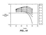
- FIG. 10 is a graphical representation showing a plot of the logarithm of peak height ratio versus the percentage of water in a sample using an embodiment of the present invention
- FIG. 11 panels a, b, and c are representative electrochromatograms showing plots of absorbance versus retention time using an embodiment of the present invention
- FIGS. 12A , 12 B, and 12 C are representative electrochromatograms showing plots of absorbance versus retention time using an embodiment of the present invention
- FIG. 13 panels a and b are representative electrochromatograms showing plots of absorbance versus retention time using an embodiment of the present invention
- FIG. 14 panels a, b, c, d, and e are representative electrochromatograms showing plots of absorbance versus retention time using an embodiment of the present invention
- FIG. 15 panels a, b, c, d, e, and f are representative electrochromatograms showing plots of absorbance versus retention time using an embodiment of the present invention
- FIG. 16 panels a and b are representative electrochromatograms showing plots of absorbance versus retention time using an embodiment of the present invention.
- FIG. 17 panels a, b, c, d, and e are representative electrochromatograms showing plots of absorbance versus retention time using an embodiment of the present invention.
- FIG. 1 is a longitudinal cross-sectional view of a separation column, according to an embodiment of the present invention.
- the separation column 11 includes a separation channel 13 in tube 12 and a separation medium 15 in the channel 13 .
- the separation column 11 may be a capillary or a planar chip, and the separation channel 13 may include a detection window.
- the separation medium 15 fills at least a section of the channel 13 .
- the medium 15 is homogeneous and preferably does not have frits or chromatographic particles.
- the medium 15 may be attached to a channel wall 17 of the channel 13 .
- the medium 15 may be covalently bound to the channel wall 17 .
- Tube 12 can have many different cross-sections, such as a circular cross-section. Alternatively, tube 12 can have an elongated cross-section. These and other cross-sections are possible for tube 12 and are within the scope of the invention.
- Tube 12 may be a round capillary typically made of fused silica. The inside diameter (i.d.) of the capillary may be from about 10 ⁇ m to about 1000 ⁇ m, preferably from about 75 ⁇ m to about 500 ⁇ m.
- Tube 12 may be a planar chip or a confined space, such as a column confined by two sheets.
- the medium 15 includes porous matrix, and the porous matrix includes a metal organic, or metalorganic, polymer, such as a photopolymer, wherein the term metal organic, or metalorganic, refers to a material that comprises an organic ligand attached to a metal atom or a metalloid atom.
- a precursor of the polymer may be a metal alkoxide, wherein the term metal alkoxide refers to a metal organic, or metalorganic, material, that has a metal-oxygen-carbon linkage or metalloid-oxygen-carbon linkage.
- metal is used in connection with a metal organic, or metalorganic, material, or in connection with a metal alkoxide, it encompasses metals and metalloids.
- the metal or metalloid may be aluminum, barium, antimony, calcium, chromium, copper, erbium, germanium, iron, lead, lithium, phosphorus, potassium, silicon, tantalum, tin, titanium, vanadium, zinc, or zirconium.
- the precursor may include a photoactive group, such as methacrylate.
- the precursor may be trimethoxysilypropyl methacrylate, also known as methacryloxypropyltrimethoxy silane.
- a porous matrix 15 with different physical properties can be used to prepare a porous matrix 15 with different physical properties, such as pore size, polymer charge density, and hydrophobicity. Control of the pore shapes and sizes through the use of different porogens can result in a porous matrix with a wide distribution of pore sizes (i.e., pore-size gradient).
- a porous matrix with a pore-size gradient can function as “molecule sorter” in capillary electrophoresis and capillary electrochromatography.
- the porous matrix 15 can separate a mixture of large molecules whose size structures or chemistries (e.g., DNA fragments) may differ.
- separation columns 11 can be designed for reversed-phase, size-exclusion, affinity, ion-exchange chromatographies, etc.
- a porous matrix 15 may be a mixed phase porous matrix prepared from a mixture of monomers.
- the monomers may include methacryloxypropyltrimethoxy silane, bis(triethoxysilyl)ethane, and bis(triethoxysilyl)octane.
- the mixed phase porous matrix may have different properties, such as hydrophobicity.
- the porous matrix has an affinity for analytes and can be used to both preconcentrate and separate a sample of analytes.
- the affinity for an analyte may be described by the retention factor, k, of the analyte.
- the retention factor is affected by the nature of the solvent, the nature of the analyte, the length of the column, the permeability of the porous matrix, the hydrophobicity of the porous matrix, and the detailed
- the separation column 11 may be used for analytic or semipreparative work. Separation of analytes in the submilligram to milligram quantities may become possible with preconcentration on separation columns 11 . For example, more than about 100-nL of sample solution at analyte concentrations in the mM levels can be injected into the column without significant evidence of overloading.
- a method of preparing a monolith in the separation column 11 is provided.
- a separation column is provided.
- the separation column may be a round capillary typically made of fused-silica.
- the inside diameter (i.d.) of the capillary may be from about 10 ⁇ m to about 1000 ⁇ m, preferably from about 75 ⁇ m to about 500 ⁇ m.
- a mixture that includes a metal organic compound is introduced into the separation column.
- the mixture forms a solid, porous matrix via photoinitiated polymerization.
- the mixture may comprise a metal organic monomer, a porogen, and a photoinitiator.
- the metal organic monomer may be a metal alkoxide, such as a silane, or a mixture of metal alkoxides.
- the metal may be aluminum, barium, antimony, calcium, chromium, copper, erbium, germanium, iron, lead, lithium, phosphorus, potassium, silicon, tantalum, tin, titanium, vanadium, zinc, or zirconium.
- the metal alkoxide may include a photoactive group, such as methacrylate.
- the precursor may be trimethoxysilypropyl methacrylate, also known as methacryloxypropyltrimethoxy silane.
- the precursor may be a mixture of methacryloxypropyltrimethoxy silane and another precursor, such as bis(triethoxysilyl)ethane or bis(triethoxysilyl)octane.
- the metal organic monomer may be added to an acid or base catalyst for the hydrolysis of the precursor.
- the catalyst converts the alkoxy groups to hydroxyl groups.
- a silane may undergo the following hydrolysis reaction to form a fully hydrolyzed silane: Si(OR) 4 +4H 2 O ⁇ Si(OH) 4 +4ROH (3).
- the hydrolysis reaction may stop at a partially hydrolyzed silane, Si(OR) 4-n (OH) n .
- the metal organic monomer and the catalyst may be stirred for about zero minutes to about twenty-four hours.
- a porogen or a mixture of porogens may be mixed with the metal organic monomer and the catalyst, and the mixture may be stirred for about zero minutes to about twenty-four hours.
- the metal organic monomer may undergo a condensation reaction to form dimers, trimers, and other oligomers.
- a partially hydrolyzed silane may undergo the following condensation reaction: 2(RO) 3 SiOH ⁇ (RO) 3 Si—O—Si(OR) 3 +H 2 O (4). Larger oligomers may be formed by increasing the temperature of the reaction.
- the porogen provides a molecular template to form pores within the matrix.
- the porogen may be a solvent, such as toluene or a 1:1 mixture of hexane and toluene, a polymer, or an inorganic salt, such as sodium chloride powder or sodium sulfate.
- the polymeric porogen may be poly(methyl methacrylate) or polystyrene, as reported by D. Horak, J. Labsky, J. Pilar, M. Bleha, Z. Pelzbauer, F. Svec, Polymer 34(16) (1993) pp. 3481-89.
- the porogen may be selected controllably to form pores in the matrix 15 .
- the porosity of the matrix may be controlled by the type of chemical (i.e., porogen) used and its volume or concentration in the reaction solution.
- a molar or volume ratio of monomer to porogen may be selected to form pores in the mixture.
- the physical properties (e.g., pore sizes) of the matrix may be controlled.
- the photoinitator or a photoactive group, such as methacrylate, on the monomer absorbs light to catalyze the polymerization of the metal organic compound.
- the photoinitiator may be Irgacure 1800, available from Ciba Geigy, Tarrytown, N.Y.
- the coating is first removed to make an irradiation window.
- the length of the coating will determine the length of the porous matrix formed within the separation column.
- the fixture is introduced into the separation column.
- the mixture may be flowed through the separation column using a syringe.
- the ends of the separation column may be sealed.
- the mixture is irradiated, thereby forming a fritless, homogeneous separation medium in the separation column.
- the separation column may be exposed to radiation for a short period of time, such as about five minutes.
- the wavelength of the radiation is dependent on the type of photoinitiator or photoactive group used in the reaction.
- the radiation may include visible or ultraviolet light.
- radiation of 365 nm maybe used for the photoinitiator Irgacure 1800.
- the photoactive group methacrylate may be photopolymerized at a wavelength of 300 nm or 365 nm, as reported in C. Yu, F. Svec, J. M. J. Frechet, Electrophoresis 21(1) (2000) pp. 120-27 and H.-G. Woo, L.-Y. Hong, S.-Y. Kim, S.-H. Park, S.-J. Song, H.-S. Ham, Bull. Korean Chem. Soc. 16 (1995) pp. 1056-59,
- a photochemical reaction occurs when the mixture is exposed to radiation.
- the photoinitator or photoactive group on the monomer absorbs the light to catalyze the polymerization of the metal organic compound.
- the photochemical route to the preparation of a porous matrix has many advantages: (1) short preparation time, (2) control of the pore size, (3) control over the placement and length of the porous matrix, (4) high mechanical strength, and (5) avoidance of high temperatures that lead to cracking.
- the separation medium preferably does not have frits or chromatographic particles, so the preparation of the separation medium is easier than preparation of a conventional separation medium with frits or chromatographic particles is.
- an organic solvent may be introduced into the separation column.
- the organic solvent may be ethanol.
- the porous matrix may be washed clean of any unreacted material, the porogen, and the photoinitiator using an organic solvent.
- the solvent may be flowed through the separation column using a syringe or other means.
- the separation column may be conditioned with a separation solution before using the column for separation.
- a separation solution may comprise a buffer, such as aqueous ammonium acetate, and an eluting solvent, such as acetonitrile.
- a method to separate a sample of analytes is provided.
- a sample of analytes is introduced in a sample solution through a separation column 11 .
- Analytes includes neutral species, such as polycyclic aromatic hydrocarbons, alkyl benzenes, alkyl phenyl ketones, and steroids, and charged species, such as peptides.
- the sample solution may comprise a buffer, such as aqueous ammonium acetate, and an eluting solvent, such as acetonitrile.
- the separation column 11 includes a separation channel 13 and a fritless, homogeneous separation medium 15 in the channel 13 .
- the separation column 11 may be a capillary or planar structure.
- the separation medium 15 preferably does not have frits or chromatographic particles.
- the use of a homogeneous separation medium is advantageous because, in some applications, the use of chromatographic particles (i.e., inhomogeneous separation phase) introduces unwanted broadening (i.e., lack of resolution).
- the separation medium 15 may possibly include two sections containing substantially the same porous homogeneous stationary phase, and the two sections may be separated by another section, such as a monolith with a different pore size or surface charge.
- the separation medium 15 is continuous.
- the separation medium 15 includes a metal organic photopolymer and concentrates the analytes on the column.
- the sample may be introduced by applying a pressure or a voltage to the column 11 .
- the pressure may be 0.5 psi or 20 psi for a period of time, such as two to 1920 seconds, or a field strength of about 40 V/cm may be applied for a period of time.
- an injection plug length of greater than about two centimeters may be injected into the column 11 .
- the analyte is concentrated by the column 11 .
- the extent of preconcentration is purely dependent on the retention factor, the k value.
- the retention factor is affected by the nature of the solvent, the nature of the analyte, and the detailed morphology of the separation medium.
- the flow rate hardly influenced the extent of preconcentration.
- the highly porous nature of the porous matrix results in a high mass transfer rate for the analyte, which facilitates the preconcentration effect.
- the high mass transfer rates arise from the enhanced accessibility of the analytes to the binding sites of the porous structure. Because of the high mass transfer rates, the kinetics of analyte-porous matrix interaction (i.e., the partitioning of the analyte between the mobile and stationary phases) is not the rate-limiting step in the separation.
- the high mass transfer rate distinguishes this separation method from previous forms of chromatographic separations. With this separation method, because of the high mass transfer rate, it is possible to inject and concentrate larger volumes of sample solution than in columns containing normal chromatographic materials.
- the total preconcentration effect is directly proportional to the retention factor, with longer injection plug lengths (e.g., greater than about 25 mm) leading to severe peak broadening of analytes having low-k values. This behavior implies a maximum length of sample plug for each analyte before peak shape becomes compromised.
- a major advantage of on-line preconcentration is that it lowers the detection limit for a given analyte.
- preconcentration may be used to clean up the analytes from possible interfering species found in the sample matrix.
- a separation solution is caused to flow through the column 11 , thereby separating and eluting the analytes.
- the separation solution may be caused to flow by applying a voltage or a pressure to the column 11 .
- the pressure may be 0.5 psi or 20 psi for a period of time, such as two to 1920 seconds, or a field strength of 300 V/cm may be applied for a period of time.
- the separation solution may comprise a buffer, such as aqueous ammonium acetate, and an eluting solvent, such as acetonitrile.
- the separation solution is the same as the sample solution.
- the porous matrix acts to extract the analytes from solution as well as provides the stationary phase for chromatographic separation of the analytes. It is this extractor-separator combination that gives this method such power. For example, more than about two-centimeter plugs of sample solution can be loaded into the capillary and concentrated using a separation solution that is the same as the sample solution.
- a solvent gradient may be used to further enhance preconcentration of the analytes.
- the sample may be dissolved in a solution with a higher concentration of a buffer (e.g., water) than in the separation solution.
- the higher concentration of the buffer in the sample solution increases the affinity of the sample to the stationary phase.
- the plug length can be longer than the length of the column. For example, injection of a 91.2-cm plug, which was more than three times the total length of the capillary, was possible with only a minor loss in resolution. Improvements in peak heights obtained under gradient conditions can be more than a thousand-fold.
- the first approach is to increase the organic solvent ratio between the separation solution and the sample solution.
- the second approach is to increase the retention factor k in the separation by increasing the percentage of water in the separation solution while maintaining a reasonable percentage of organic solvent between the separation solution and the sample solution. Analysis is faster with the first approach, whereas the resolution is better with the second one.
- sample stacking in addition to the effect exerted by the porous matrix, sample stacking may be used to further enhance the preconcentration of analytes.
- Sample stacking is the focusing of charged analytes when analytes pass the concentration boundary that separates regions of high and low electric field strengths.
- the high electric field zone is a lower conductivity sample solution containing more of the eluting solvent, whereas the low electric field region is a higher conductivity separation solution.
- the eluting solvent such as acetonitrile, has a lower conductivity than the buffer, such as aqueous ammonium acetate.
- a higher concentration of the eluting solvent results in lowering the sample matrix conductivity.
- the separation column is prepared with the separation solution.
- analytes are introduced into the separation column and a voltage is applied, the analytes in the sample solution at the inlet of the column rapidly accelerate toward the separation solution (lower electric field strength) already in the column, where on crossing the boundary between the sample solution and the separation solution, they slow down and stack into narrow zones at the interface.
- Sample stacking is basically caused by the change in electrophoretic velocity at the concentration boundary. Electrophoretic velocity is the product of electrophoretic mobility and electric field strength. Focusing occurs (sample stacking) when the electrophoretic velocity decreases at the concentration boundary. Sample stacking is also explained using the fundamentals of isotachophoresis and Kohlrausch rules.
- the first approach is to increase the percentage of organic solvent, such as acetonitrile.
- the second is to decrease the concentration of the buffer component in the sample solution.
- Increasing the percentage of acetonitrile or other suitable organic solvent is especially useful for real samples containing high concentration of salts. Desalting, for example by dialysis, is therefore not necessary to make a lower conductivity solution for injection.
- Use of organic solvents is also usefull for biological samples when deproteination is part of the sample preparation.
- Fused-silica capillaries 75- ⁇ m i.d. ⁇ 365- ⁇ m o.d.
- Methacryloxypropyltrimetoxysilane MPTMS
- HPLC-grade toluene, phenanthrene, pyrene, alkyl benzenes, alkyl phenyl ketones, and steroids were purchased from Sigma-Aldrich, Milwaukee, Wis.
- Irgacure 1800 was received from Ciba, Tarrytown, N.Y.
- the monomer stock solution was prepared just prior to use by adding 375 ⁇ L of MPTMS to 100 ⁇ L of 0.12 N HCl. This solution was stirred at room temperature for approximately thirty minutes to afford a clear, monophasic solution. An appropriate amount of toluene (porogen) was added to the monomer stock solution, as shown below in Table 1.
- a 15-cm stripe of the polyimide coating on a 30-cm long capillary was removed using a razor blade positioned at 45° to the capillary surface.
- the mechanical stability of the capillary was remarkably good despite the removal of a stripe of polyimide coating.
- the irradiation light entered the capillary only through this 15-cm stripe. No monolith was formed in the capillary where the polyimide coating (“mask”) remained intact.
- the capillaries were washed with ethanol using a hand-held syringe to removed unreacted reagents or porogens. Because the monoliths were highly permeable, high pressures were not required to drive liquid through the capillaries. Once the unreacted reagents were removed, the monolith became opaque and could be viewed clearly through the capillary without the aid of a microscope. The homogenity of the porous matrix was confirmed at 100 ⁇ magnification. Burning off the polyimide coating immediately after the monolith section with fuming sulfuric acid made a detection window.
- the capillary was successfully installed in the cartridge without any damage.
- the capillary was conditioned with the separation buffer for approximately five minutes using a syringe and a band-held vise. Once in the instrument, the capillary was further conditioned by pressure rinsing (20 psi) with the separation buffer or by electrokinetically conditioning at 5 kV or 10 kV for thirty minutes.
- the analytes were prepared in the mobile phase to prevent gradient effects during the CEC experiments.
- the mobile phase was made up of various ratios (v/v) of 50 mM ammonium acetate, water, and acetonitrile.
- a new sample solution was used for every injection to maintain the same concentration of acetonitrile in the sample solution and the mobile phase.
- FIG. 2A is a representative electrochromatogram showing a plot of absorbance versus retention time for column B.
- the separation was performed with a 50 mM ammonium acetate/water/acetronitrile (1/3/6) solution.
- the sample solution was injected at 0.5 psi pressure for three seconds, and the separation was performed with an applied voltage of 1 kV at a temperature of 20° C. and detected at 214 nm.
- the elution order of the separation was (1) thiourea, (2) tetrahydrofuran, (3) naphthalene, (4) phenanthrene, (5) fluoranthene, (6) pyrene, (7) 1,2-benzanthracene, and (8) 1,2,5,6-bienzanthracene.
- FIG. 2B is a representative electrochromatogram showing a plot of absorbance versus retention time for column D.
- the separation was performed with a 50 mM ammonium acetate/water/acetronitrile (1/4/5) solution.
- the sample solution was injected at 0.5 psi pressure for three seconds, and the separation was performed with an applied voltage of 15 kV at a temperature of 20° C. and detected at 200 nm.
- the elution order of the separation was (1) benzene, (2) toluene, (3) ethylene benzene, (4) propyl benzene, (5) butyl benzene, and (6) hexyl benzene.
- the elution order of the column was similar to that of reversed-phase chromatography with the larger molecular weight or more hydrophobic analytes eluting later than the smaller molecular weight or more hydrophilic analytes. Elution of the analytes in both figures occurred in less than seven minutes. Bubble formation was not a problem during the CEC experiments, for which the typical operating currents were between 3 and 10 ⁇ A.
- FIG. 3 is a representative electrochromatogram showing a plot of absorbance versus retention time for column D.
- the separation was performed with a 50 mM ammonium acetate/water/acetronitrile (1/3/6) solution.
- the sample solution was injected at 0.5 psi pressure for three seconds, and the separation was performed with an applied voltage of 1 kV at a temperature of 20° C. and detected at 214 nm.
- a sample of thiourea, napthalene, phenanthrene, and pyrene was separated within 110 minutes at an applied pressure of only 20 psi (the maximum limit of the instrument). Peak tailing was most severe for pyrene because of its strong interaction with the porous matrix, and tailing was not observed for thiourea, which has low retention on the column.
- FIG. 4A is a scanning electron micrograph of the cross-section of a metal organic photopolymer formed with 80% (v/v) toluene (capillary B) in a 75- ⁇ m-i.d. capillary column.
- the micrograph showed an interconnecting network of 1- ⁇ m spherical structures through which micrometer-sized macropores (as large as 5 ⁇ m) are interspersed.
- FIG. 4B is a scanning electron micrograph of the cross-section of a metal organic photopolymer formed with 50% (v/v) toluene in a 75- ⁇ m-i.d. capillary column.
- the structure shown in FIG. 4B was a dense photopolymer with macropores of 2 ⁇ m or less in diameter. Consequently, the matrix in FIG. 4B was less permeable, and a significant back pressure occurs. No liquid could be driven through the column at pressures near 200 psi.
- the permeability of a porous matrix was determined by the linear velocity of the porous matrix, which is proportional to permeability as described in Darcy's law.
- the permeability of a porous matrix as a function of the macropore size was highly dependent on the volume and type of porogen used to prepare the photopolymer.
- the linear velocity is 12.3 cm/min
- an 80% (v/v) column (column B) had a linear velocity of 3.3 cm/min
- a column made with 73% (v/v) toluene (column D) had a linear velocity of 0.6 cm/min.
- a mixture of 375 ⁇ L of MPTMS and 100 ⁇ L of 0.12 M hydrochloric acid was stirred for thirty minutes at room temperature. 27 parts of this mixture were combined with 73 parts of toluene to give 200 ⁇ L of the final solution. 5% by weight of the final solution of the photoinitator Irgacure 1800 was added, and the resulting sol-gel solution was stirred for five minutes before use.
- a 75- ⁇ m i.d. ⁇ 365- ⁇ m o.d. fused silica capillary was filled with the sol-gel solution, and the separation column was exposed to UV light in a Spectrolinker Xl-1500 at 365 nm to affect photopolymerization.
- the polymerization length of the porous matrix was controlled by removing a 15-cm strip of the polyimide coating of the capillary prior to irradiation for five minutes. Unreacted reagents were flushed with ethanol. The total length of the capillary was 25.6 cm (18.8 cm from inlet to the detector window). The resulting column was conditioned with the separation solution prior to use.
- FIGS. 5A and 5B are representative electrochromatograms showing plots of absorbance versus retention time using an embodiment of the present invention.
- the figures illustrate the increase in detection sensitivity with an increase in injected plug length in the CEC separation of a mixture containing the small molecule, thiourea, three polycyclic aromatic hydrocarbons (PAHs), and eight alkyl phenyl ketones.
- PAHs polycyclic aromatic hydrocarbons
- the sample was prepared in the separation solution.
- the sample and separation solutions were 50 mM ammonium acetate/water/acetonitrile (1/4/5).
- the plug lengths were 0.1 mm, 6.8 mm, 13.7 mm, 27.4 mm, and 34.2 mm.
- the 0.1 mm plug length was for an applied pressure of 0.5 psi, whereas all other plug lengths were for an applied pressure of 20 psi.
- the applied voltage for the separation was 20 kV, and the absorbance was measured at 214 nm.
- the elution order of the column was (1) 12.5. ⁇ M thiourea, (2) 51.0 ⁇ M naphthalene, (3) 1.0 ⁇ M phenanthrene, and (4) 123 ⁇ M pyrene.
- the column was prepared in the same manner as the column as described earlier, except that the column was post-modified by continuous flow of (3,3,3-trifluoropropyl)trichlorosilane for thirty minutes at room temperature and followed by rinsing with toluene.
- the plug lengths were 0.7 m, 7.2 mm, 10.7 mm, 17.9 mm, and 28.6 mm.
- the applied voltage was 15 kV, and the absorbance was measured at 254 nm.
- the elution order of the column was (1) 5 ⁇ M thiourea, (2) acetophenone, (3) propiophenone, (4) butyrophenone, (5) valerophenone, (6) hexanophenone, (7) heptanophenone; (8) octanophenone, and (9) decanophenone.
- the concentration of each of the alkyl phenyl ketones was 0.1 ⁇ g/mL in the separation solution.
- the peaks were barely visible with the typical injection of a 0.1 mm plug length, but the peak heights increased when the plug length increased from 6.8 to 34.2 mm.
- the separation column an embodiment of the present invention, allowed for the injection of a longer plug length than a typical separation column does.
- the peak heights increased when the plug length was increased from 0.7 mm to 57.3 mm. As the plug length was increased, all four peaks showed increased broadening, but the later eluting peaks are more symmetrical to a small extent than the earlier ones.
- the improvement in peak heights for a 27.4-mm injection compared to a typical injection of 0.1 mm is 50, 125, and 127 times for naphthalene, phenanthrene, and pyrene, respectively.
- the sample solution in the 27.4-mm injection is a 10-fold dilution of the sample in the typical 0.1-mm injection.
- the separation column was prepared as described in Example 3.
- the sample and separation solution was 50 mM ammonium acetate/water/acetonitrile (1/3/6).
- the samples were injected at 1 kV.
- the applied voltage was 15 kV, and the absorbance was detected at 214 nm.
- FIG. 6 is a representative electrochromatogram of a plot showing absorbance versus retention time using an embodiment of the present invention. 39.0 mM of naphthalene in the separation solution was injected for five seconds, as represented by signal a, and a 3.9 mM of naphthalene in the separation solution was injected for eighty-five seconds, as represented by signal b.
- the corrected peak areas (peak area/migration time) for both electrochromatograms were made close to each other by controlling the injection time of the ten-fold dilution of sample.
- Preconcentration was evidenced by the slightly higher peak height for the longer injection of diluted sample and almost the same corrected peak widths (peak width/migration time) for both experiments, despite the different sample concentration.
- the shift in migration time on line b was caused by the longer injection time, which made the center of the sample plug closer to the detector window.
- FIG. 7 panels a and b are representative electrochromatograms showing plots of absorbance versus retention time using an embodiment of the present invention.
- the separation solution was 50 mM phosphoric acid/water/acetonitrile (1/5/4).
- the applied voltage was 15 kV, and the absorbance was detected at 214 nm.
- FIG. 7 (panel a) shows a 0.5 psi injection at 0.1 mm plug length of test peptides
- FIG. 7 (panel b) shows a 0.5 psi injection at 12 mm plug length of test peptides.
- test peptides which were charged analytes, were (1) bradykinin, (2) angiotensin II, (3) tripeptide I, (4) tripeptide II, and (5) methionine enkephalin.
- concentration of the peptides were 16.7 ⁇ g/ml.
- the cathode directed velocities of the peptides were dictated by both electrophoretic and electroosmotic flow effects.
- FIG. 8 panels a, b, and c are representative electrochromatograms showing plots of absorbance versus retention time using an embodiment of the present invention.
- FIG. 8 shows an analysis of a urine sample, spiked with 0.1 mM hydrocortisone (peak 1 ), 0.3 mM progesterone (peak 2 ) and 0.2 mM cortisone (peak 3 ).
- Four parts of spike or unspiked urine were mixed with six parts of acetonitrile and centrifuged to remove proteins.
- One part of each supernatant was mixed with one part of 50 mM ammonium acetate/water/acetonitrile (1/7/2) before injection.
- FIG. 8 (panel a) shows an injection plug length of 0.1 mm
- FIG. 8 (panel b) shows an injection plug length of 21.4 mm
- FIG. 8 (panel c) represents a 21.4-mm injection plug length of urine blank.
- the separation solution consisted of 50 mM ammonium acetate/water/acetonitrile (1/5/4).
- the applied voltage for the separation was 17 kV, and the absorbance was measured at 254 nm.
- these steroids were detected and quantified with a 21.4-mm injection of the sample solution, but are weakly detected with a typical 0.1-mm injection.
- a comparison between the blank run and the spiked run showed that the sample matrix, which still contained other biomolecules, did not significantly interfere with steroid analysis on the separation column. This result demonstrates the usefulness of the technique for biofluid analysis.
- FIG. 9 panels a, b, c, d, and e are representative electrochromatograms showing plots of absorbance versus retention time using an embodiment of the present invention.
- Sample plug lengths of 1.1 cm were injected.
- the separation solution was 5 mM ammonium acetate in 60% acetonitrile, and the sample solutions were 5 mM ammonium acetate in 60% acetonitrile (panel a), 50% acetonitrile (panel b), 40% acetonitrile (panel c), 30% acetonitrile (panel d), and 20% acetonitrile (panel e).
- the applied voltage for the separation was 15 kV, and the absorbance was detected at 254 nm.
- the elution order was (1) thiourea, (2) acetophenone, (3) propiophenone, (4) butyrophenone, (5) valerophenone, (6) hexanophenone, (7) heptanophenone, (8) octanophenone, and (9) decanophenone.
- the concentration of each analyte was 2 nl/ml.
- FIG. 10 is a graphical representation of a plot showing the logarithm of peak height ratio (peak height obtained from a higher concentration of water in the sample matrix divided by peak height obtained from a sample matrix similar to that of the separation solution) versus the percentage of water in the sample matrix.
- the data indicated that a limit exists to which the peak heights can be improved by increasing the concentration of the buffer in the sample matrix. Preconcentration was improved owing to the increased attraction of the analytes to the porous matrix.
- the value for the logarithm of the peak height ratio was less than 1, about 1, or greater than 1 there was a decrease, no change, or increase, respectively, in peak height compared to a similar injection using the separation solution as the sample matrix.
- Peak heights improved when the water concentration was increased from 40% to 50% and from 50% to 60%. Peak heights did not improve when the percentage of water was increased from 60% to 70% or more, except for the two lowest k analytes (acetophenone and propiophenone) when the percentage of water was increased from 60% to 70%. Peak heights worsened for the higher k analytes (heptanophenone, octanophenone, and decanophenone) in the 80% water matrix. The reason for the decrease in peak heights is the decrease in the solubility of the high k analytes in the highly aqueous sample matrix.
- the corrected peak areas which is a measure of the amount of sample loaded for octanophenone and decanophenone is 10% to 60% lower in the 80% water matrix compared to the other sample matrices used.
- the test APKs in succeeding experiments were prepared in matrices having at least 30% acetonitrile.
- FIG. 11 panels a, b, and c are representative electrochromatograms showing plots of absorbance versus retention time using an embodiment of the present invention.
- the separation solution is 5 mM ammonium acetate in 60% acetonitrile.
- the plug lengths were 0.2 cm for a sample solution of 5 mM ammonium acetate in 60% acetonitrile (panel a); 2.74 cm for the same sample solution was used in panel a (panel b), and 2.74 cm for a sample solution of 5 mM ammonium acetate in 30% acetonitrile (panel c).
- Other conditions and identification of peaks are the same as in Example 7.
- the gradient condition as shown in FIG. 11 (panel c), showed improved resolution and peak shapes. Improvements in peak heights under the gradient condition illustrated in FIG. 11 (panel c) were 36, 35, 38, 41, 42, 38, 32, and 24 times for acetophenone, propiophenone, butyrophenone, valerophenone, hexanophenone, heptanophenone, octanophenone, and decanophenone, respectively.
- FIGS. 12A , 12 B, and 12 C are representative electrochromatograms showing plots of absorbance versus retention time using an embodiment of the present invention.
- the plug lengths were 2.74 cm for sample solution of 5 mM ammonium acetate in 40% acetonitrile (FIG. 12 A), 2.74-cm for sample solution of 5 mM ammonium acetate in 30% acetonitrile (FIG. 12 B), and 5.48 cm for a sample solution the same as in FIG. 12B (FIG. 12 C).
- the separation solutions were 5 mM ammonium acetate in 60% acetonitrile ( FIG. 12A ) and 5 mM ammonium acetate in 50% acetonitrile (FIGS. 12 B and 12 C). Other conditions and identification of peaks are the same as in Example 7.
- the kvalues were higher in FIG. 12B than in FIG. 12A because of the high percentage of water in the separation solution.
- the analyte molecules were more attracted to the PSG phase at high percentages of water.
- the distribution constant K (number of moles of solute in the PSG phase divided by the number of moles of solute in the separation solution), which is directly proportional to k increases with increasing concentration of water in the separation solution.
- the k values for acetophenone, propiophenone, butyrophenone, valerophenone, hexanophenone, heptanophenone, octanophenone, and decanophenone were 0.29, 0.47, 0.65, 0.92, 1.28, 1.76, 2.37, and 4.25, respectively.
- the percentage of organic solvent ratio between the separation solution and sample matrix was kept at the same value for FIGS. 12A and 12B .
- the result in FIG. 12B shows that for analytes with lower k values (acetophenone and propiophenone) there were slight increases in peak heights compared to FIG. 12 A. For the other test solutes, there are some decreases in peak heights.
- FIG. 12C illustrates what happens for a longer injection plug of 5.48 cm and a higher percentage of water in the separation solution. Improvements in peak heights were 31, 33, 55, 44, 44, 37, 29, and 19 times for acetophenone, propiophenone, butyrophenone, valerophenone, hexanophenone, heptanophenone, octanophenone, and decanophenone, respectively. As in FIG. 11 (panel c), the improvements in peak heights do not follow k, unlike in nongradient conditions. The improvements in peak heights were comparable to those obtained with a higher percentage of organic solvent between the separation solution and the sample matrix ( FIG. 11 , panel c). Note that the injection plug is two times shorter in FIG. 11 (panel c) than in FIG. 12 C.
- FIG. 13 panels a and b are representative electrochromatograms showing plots of absorbance versus retention time using an embodiment of the present invention.
- the plug lengths were 0.22 mm (panel a) and 19.5 cm (panel b).
- the separation solution was 5 mM ammonium acetate in 60% acetonitrile.
- the sample solutions were: 5 mM ammonium acetate in 60% acetonitrile (panel a) and 36% acetonitrile (panel b).
- the sample concentrations were 11 to 53 ⁇ g/ml (panel a) and 1.1 to 5.3 ⁇ g/ml (panel b).
- the applied voltage was 30 kV, and the absorbance was detected at 214 nm.
- the elution order was thiourea (peak 1 ), naphthalene (peak 2 ), phenanthrene (peak 3 ), pyrene (peak 4 ), and benz(e)acephenanthylene (peak 5 ).
- FIG. 13 (panel b) A solvent gradient improved detection of four PAHs, as shown in FIG. 13 (panel b).
- FIG. 13 (panel a) is a 0.22-mm typical injection of sample prepared in the separation solution.
- FIG. 13 (panel b) is a 19.5-cm injection using a gradient where the sample is in a 36% acetonitrile matrix, which provides a high percentage of organic solvent between the sample solution and the separation solution. Longer than 19.5-cm plug lengths cause broadering of the naphthalene peak.
- the injection length is longer than the length from the inlet to the detector window (18.8-cm).
- the faster eluting thiourea zone is actually observed during the sample injection.
- the thiourea zone is therefore at the detection window at the start of the separation voltage.
- FIG. 14 panels a, b, c, d, and e are representative electrochromatograms showing plots of absorbance versus retention time using an embodiment of the present invention.
- the plug lengths were 0.23 mm (panel a), 7.6 cm (panel b), 22.8 cm (panel c), 45.6 cm (panel d), and 91.2 cm (panel e).
- the separation solution was 5 mM ammonium acetate in 60% acetonitrile.
- the sample solutions were: 5 mM ammonium acetate in 60% acetonitrile (panel a) and 40% acetonitrile (panels b, c, d, and e).
- the sample concentrations were 9 to 50 ⁇ g/ml (panel a), 0.9 to 5 ⁇ g/ml (panels b, c, d, and e).
- the applied voltage was 22 kV, and absorbance was detected at 254 nm.
- the elution order was thiourea (peak 1 ), decanophenone (peak 2 ), and pyrene (peak 3 ).
- the electrochromatogram in panel d or e is believed to be the first demonstration in CEC showing sample injections longer than the total capillary length.
- the volume of sample injected was also greater than 1 ⁇ l.
- a comparison of the peak heights obtained in panels a and e suggests improvements in peak heights of 1118 times and 1104 times for decanophenone and pyrene, respectively. These values are the highest reported sensitivity improvements for neutral analytes using a simple on-line preconcentration technique in CEC.
- the strong interaction of the analytes to the porous matrix and the inherent rapid mass transfer characteristics of the porous matrix allowed for the observation of such marked preconcentration effects.
- FIG. 15 panels a, b, c, d, e, and f are representative electrochromatograms showing plots of absorbance versus retention time using an embodiment of the present invention.
- the plug lengths were 0.1 mm (panel a) and 1.8 cm (panels b, c, d, e, and f). Injections were done using pressure wherein the injection length is fixed at 1.8 cm.
- the sample solutions were the same as the separation solution (panels a and b), 10 mM phosphoric acid in 20% acetonitrile (panel c), 10 mM phosphoric acid in 70% acetonitrile (panel d), 50 mM phosphoric acid in 40% acetonitrile (panel e), 0.05 mM phosphoric acid in 40% acetonitrile (panel f).
- the separation solution was 10 mM phosphoric acid in 40% acetonitrile.
- the peptide concentrations were 16.7 ⁇ g/ml each, the applied voltage was 12 kV, and the absorption detection was at 214 nm.
- the elution order was bradykinin (peak 1 ), angiotensin II (peak 2 ), tripeptide I (peak 3 ), tripeptide II (peak 4 ), and methionine enkephalin (peak 5 ).
- Destacking is the broadening of charged analytes when analytes pass the concentration boundary that separates regions of low and high electric field strengths.
- the low electric field zone is the high conductivity sample matrix containing more water.
- Destacking is also shown in FIG. 15 (panel e) where the sample is prepared in a matrix having a higher concentration of buffer component and a similar percentage of acetonitrile compared to the separation solution.
- FIG. 16 panels a and b are representative electrochromatograms showing plots of absorbance versus retention time using an embodiment of the present invention.
- the injections were 0.1 mm using 0.5 psi pressure (panel a) and 15-s at 5 kV (panel b).
- the sample solutions were 10 mM phosphoric acid in 40% acetonitrile (panel a) and 0.5 ⁇ M phosphoric acid in 40% acetonitrile (panel b).
- the peptide concentrations were 16.7 ⁇ g/ml each (panel a) and 167 ng/ml each (panel b).
- the separation voltage was 12 kV.
- Other conditions are the same as in Example 13.
- Field enhanced sample injection was performed by dissolving the sample in a low conductivity matrix (0.5 ⁇ M phosphoric acid in 40% acetonitrile), followed by injection using voltage with the negative electrode at the detector end. As the voltage was applied, the low conductivity sample matrix entered the capillary by virtue of electroosmotic flow (EOF) while the cationic peptides entered the column by virtue of both EOF and electrophoretic flow. Only a very small plug of sample matrix was introduced because the low pH of the separation solution markedly decreases the EOF, which prevents the dissociation of silanol groups at the capillary walls. An unretained neutral solute (thiourea) was actually detected after 30 minutes.
- a low conductivity matrix 0.5 ⁇ M phosphoric acid in 40% acetonitrile
- the electric field in the sample matrix zone introduced into the column was much higher than the separation zone. This effect caused the high electrophoretic velocity of the cationic peptides entering the capillary.
- the high analyte electrophoretic velocity caused a large amount of peptides to be introduced, unlike in hydrodynamic injection, the volume of sample loaded limited the amount of sample introduced.
- the high analyte electrophoretic velocity also caused focusing or preconcentration of peptides at the concentration boundary between the sample matrix and separation solution (sample stacking).
- Introduction of a water plug before electrokinetic injection which is suggested to be useful in sample stacking with electrokinetic injection, did not improve the peak heights because of the similar direction of the EOF and analyte electrophoretic velocities.
- the low conductivity sample matrix that entered the capillary also maintained the enhancement of the electric field at the inlet end of the capillary during injection.
- Table 2 lists the types and volumes of reagents used to make different precursor stock solutions where the ratio of the acid catalyst to the precursor, methacryloxypropyltriethoxysilane, was varied or where the precursor was reacted with a co-precursor (to form a mixed phase PSG monolith).
- PSG monoliths PSG-A and PSG-J, prepared from solutions A and J, respectively, differ only in the volume of precursor used in the reaction with J containing a higher volume of the precursor than A. A higher volume of the precursor in the reaction should result in a denser monolith in the capillary column.
- the PSG monolith, PSG-K was prepared with the precursor and bis(triethoxysilyl)ethane as a co-precursor.
- the PSG monoliths, PSG-M and PSG-P were prepared with the precursor and different amounts of bis(triethoxysilyl)octane as the co-precursor.
- the co-precursors hydrolyze and condense with the precursor to form hybrid sols (mixed phases).
- solutions A and J the appropriate volume of the precursor was added to 100 ⁇ L of the acid catalyst (0.12 M HCl), and the resulting solution was stirred for 15 minutes at room temperature (in the dark).
- solutions K, M, and P the appropriate volume of the precursor was added to 100 ⁇ L of 0.12 M HCl followed by the addition of the appropriate amount of bis(triethoxysilyl)ethane; the resulting solution was stirred for 15 minutes at room temperature (in the dark). All of these solutions were used within two hours of their preparation.
- the capillary was prepared and conditioned in the same manner as previously described. PSG capillary column conditioning was the same as before.
- the separation factors of the monoliths for two test mixtures of alkyl phenyl ketones (APKs) and polycyclic aromatic hydrocarbons (PAHs) were determined.
- the separation factor is a measure of the analyte separation capability of a chromatographic system.
- the separation factor, ⁇ is given by k 2 /k 1 , where k is the retention factor for a particular analyte, and k 2 and k 1 are the k values for adjacent analytes.
- Table 3 lists the separation factor of each PSG monolith for naphthalene and pyrene.
- FIG. 17 panels a, b, c, d, and e are representative electrochromatograms showing plots of absorbance versus retention time using an embodiment of the present invention.
- a mixture of thiourea (T), naphthalene (N), phenanthrene (Ph), and pyrene (Py) were separated on PSG-A ( FIG. 17 , panel a), PSG-K ( FIG. 17 , panel b), PSG-J ( FIG. 17 , panel c), PSG-M ( FIG. 17 , panel d), and PSG-P ( FIG. 17 , panel e). In all cases the peaks of the different analytes were well resolved.
- N the efficiency (theoretical plate number)
- ⁇ the separation factor
- k the retention factor for a particular analyte.
- PSG-A has the lowest resolution of 2.43 for naphthalene and pyrene whereas PSG-J has a resolution of 4.35 for the same two analytes.
- the higher volume of the precursor used in the preparation of PSG-J as compared to PSG-A resulted in increased hydrophobicity of the monolith.
- the retention factors for naphthalene and pyrene on PSG-J were 0.31 and 0.79, respectively, and these values reflected the increase in the hydrophobicity of the monolith. These values represent increases of 55% and 5
- the separation column was prepared as described above in Example 15 for monolith PSG-J.
- the retention factors for napthalene and pyrene, k N and k Py were 0.31 and 0.79, respectively, for a porous matrix made with 80% toluene.
- k N and k Py were 0.10 and 0.24, respectively.
- the separation factors for 15-cm, 10-cm, and 5-cm porous matrices were 2.55, 2.52, and 2.40, respectively.
- the separation column was prepared as described above in Example 15.
- k N was 0.14 and k Py is 0.36
- k N was 0.30 and k Py was 0.74 for PSG-A made with 73% toluene.
- the separation factors for PSG-A made with 80% toluene and 73% toluene were 2.57 (0.1%RSD) and 2.47 (0.1%RSD), respectively.
- the value of k increased by 53% and 51% for naphthalene and pyrene when 73% toluene was used in the preparation of the monoliths.
- the resolution of naphthalene and pyrene differed significantly when comparing PSG monoliths made with 80% and 73% toluene.
- the pore size decreased, which was brought about by using lower volumes of toluene, the PSG surface increased with a resulting increase in the retention and resolution under the same separation solution conditions.
- the permeability of the porous matrix affects the retention of the analytes.
Landscapes
- Chemical & Material Sciences (AREA)
- Analytical Chemistry (AREA)
- Organic Chemistry (AREA)
- Chemical Kinetics & Catalysis (AREA)
- Treatment Of Liquids With Adsorbents In General (AREA)
- Folding Of Thin Sheet-Like Materials, Special Discharging Devices, And Others (AREA)
- Catching Or Destruction (AREA)
- Display Devices Of Pinball Game Machines (AREA)
- Colloid Chemistry (AREA)
- Polysaccharides And Polysaccharide Derivatives (AREA)
- Physical Or Chemical Processes And Apparatus (AREA)
Priority Applications (17)
| Application Number | Priority Date | Filing Date | Title |
|---|---|---|---|
| US09/929,275 US6866785B2 (en) | 2001-08-13 | 2001-08-13 | Photopolymerized sol-gel column and associated methods |
| US09/978,515 US6884346B2 (en) | 2001-08-13 | 2001-10-15 | Bonded phase photopolymerized sol-gel column and associated methods |
| US10/124,654 US6875348B2 (en) | 2000-02-18 | 2002-04-16 | Separation column having a photopolymerized sol-gel component and associated methods |
| PCT/US2002/025757 WO2003016859A2 (en) | 2001-08-13 | 2002-08-13 | Separation column having a photopolymerized sol-gel component and associated methods |
| PCT/US2002/025760 WO2003015891A1 (en) | 2001-08-13 | 2002-08-13 | Bonded phase photopolymerized sol-gel column and associated methods |
| EP02761357A EP1507574B1 (de) | 2001-08-13 | 2002-08-13 | Trennsäule mit photopolymerisierter sol-gel-komponente und damit zusammenhängende verfahren |
| AT02761357T ATE432117T1 (de) | 2001-08-13 | 2002-08-13 | Trennsäule mit photopolymerisierter sol-gel- komponente und damit zusammenhängende verfahren |
| CNB028185919A CN100509102C (zh) | 2001-08-13 | 2002-08-13 | 具有光聚合溶胶-凝胶组分的分离柱和相关的方法 |
| JP2003521317A JP4033834B2 (ja) | 2001-08-13 | 2002-08-13 | 光重合ゾルゲル成分を有する分離カラムおよび関連する方法 |
| AT02768529T ATE465795T1 (de) | 2001-08-13 | 2002-08-13 | Photopolymerisierte sol-gel-säule mit gebundener phase und zugehörige verfahren |
| EP02768529A EP1418997B1 (de) | 2001-08-13 | 2002-08-13 | Photopolymerisierte sol-gel-säule mit gebundener phase und zugehörige verfahren |
| ES02768529T ES2345328T3 (es) | 2001-08-13 | 2002-08-13 | Columna sol-gel fotopolimerizada de fase unida y metodos asociados. |
| DE60236165T DE60236165D1 (de) | 2001-08-13 | 2002-08-13 | Photopolymerisierte sol-gel-säule mit gebundener phase und zugehörige verfahren |
| DE60232468T DE60232468D1 (de) | 2001-08-13 | 2002-08-13 | Ente und damit zusammenhängende verfahren |
| JP2003520842A JP4295095B2 (ja) | 2001-08-13 | 2002-08-13 | 結合相光重合ゾルゲルカラムおよび関連する方法 |
| CNB02818548XA CN1315557C (zh) | 2001-08-13 | 2002-08-13 | 键合相光聚合溶胶-凝胶柱和相关的方法 |
| AU2002326633A AU2002326633A1 (en) | 2001-08-13 | 2002-08-13 | Separation column having a photopolymerized sol-gel component and associated methods |
Applications Claiming Priority (1)
| Application Number | Priority Date | Filing Date | Title |
|---|---|---|---|
| US09/929,275 US6866785B2 (en) | 2001-08-13 | 2001-08-13 | Photopolymerized sol-gel column and associated methods |
Related Child Applications (3)
| Application Number | Title | Priority Date | Filing Date |
|---|---|---|---|
| US50770700A Continuation-In-Part | 2000-02-18 | 2000-02-18 | |
| US09/978,515 Continuation-In-Part US6884346B2 (en) | 2001-08-13 | 2001-10-15 | Bonded phase photopolymerized sol-gel column and associated methods |
| US10/124,654 Continuation-In-Part US6875348B2 (en) | 2000-02-18 | 2002-04-16 | Separation column having a photopolymerized sol-gel component and associated methods |
Publications (2)
| Publication Number | Publication Date |
|---|---|
| US20030062308A1 US20030062308A1 (en) | 2003-04-03 |
| US6866785B2 true US6866785B2 (en) | 2005-03-15 |
Family
ID=25457591
Family Applications (2)
| Application Number | Title | Priority Date | Filing Date |
|---|---|---|---|
| US09/929,275 Expired - Lifetime US6866785B2 (en) | 2000-02-18 | 2001-08-13 | Photopolymerized sol-gel column and associated methods |
| US09/978,515 Expired - Lifetime US6884346B2 (en) | 2001-08-13 | 2001-10-15 | Bonded phase photopolymerized sol-gel column and associated methods |
Family Applications After (1)
| Application Number | Title | Priority Date | Filing Date |
|---|---|---|---|
| US09/978,515 Expired - Lifetime US6884346B2 (en) | 2001-08-13 | 2001-10-15 | Bonded phase photopolymerized sol-gel column and associated methods |
Country Status (5)
| Country | Link |
|---|---|
| US (2) | US6866785B2 (de) |
| AT (2) | ATE432117T1 (de) |
| AU (1) | AU2002326633A1 (de) |
| DE (2) | DE60236165D1 (de) |
| ES (1) | ES2345328T3 (de) |
Cited By (25)
| Publication number | Priority date | Publication date | Assignee | Title |
|---|---|---|---|---|
| US20020058332A1 (en) * | 2000-09-15 | 2002-05-16 | California Institute Of Technology | Microfabricated crossflow devices and methods |
| US20020109114A1 (en) * | 2000-11-06 | 2002-08-15 | California Institute Of Technology | Electrostatic valves for microfluidic devices |
| US20030134129A1 (en) * | 2001-10-11 | 2003-07-17 | Lammertink Rob G.H. | Devices utilizing self-assembled gel and method of manufacture |
| US20030164297A1 (en) * | 2002-03-04 | 2003-09-04 | Corning Incorporated | Electrophoretic inorganic porous material |
| US20040180377A1 (en) * | 2002-06-24 | 2004-09-16 | Fluidigm | Recirculating fluidic network and methods for using the same |
| US20040224380A1 (en) * | 2002-04-01 | 2004-11-11 | Fluidigm Corp. | Microfluidic particle-analysis systems |
| US20040229349A1 (en) * | 2002-04-01 | 2004-11-18 | Fluidigm Corporation | Microfluidic particle-analysis systems |
| US20050019792A1 (en) * | 2001-11-30 | 2005-01-27 | Fluidigm Corporation | Microfluidic device and methods of using same |
| US20050053952A1 (en) * | 2002-10-02 | 2005-03-10 | California Institute Of Technology | Microfluidic nucleic acid analysis |
| US20050065735A1 (en) * | 2000-06-27 | 2005-03-24 | Fluidigm Corporation | Microfluidic design automation method and system |
| US20050129581A1 (en) * | 2003-04-03 | 2005-06-16 | Fluidigm Corporation | Microfluidic devices and methods of using same |
| US20050221373A1 (en) * | 2001-04-06 | 2005-10-06 | California Institute Of Technology | Nucleic acid amplification using microfluidic devices |
| US20050252773A1 (en) * | 2003-04-03 | 2005-11-17 | Fluidigm Corporation | Thermal reaction device and method for using the same |
| US20060118895A1 (en) * | 2001-08-30 | 2006-06-08 | Fluidigm Corporation | Electrostatic/electrostrictive actuation of elastomer structures using compliant electrodes |
| US20070004033A1 (en) * | 2001-11-30 | 2007-01-04 | Fluidigm Corporation | Microfluidic device and methods of using same |
| US20070141599A1 (en) * | 1997-09-23 | 2007-06-21 | California Institute Of Technology | Methods and systems for molecular fingerprinting |
| US7413712B2 (en) | 2003-08-11 | 2008-08-19 | California Institute Of Technology | Microfluidic rotary flow reactor matrix |
| US7476363B2 (en) | 2003-04-03 | 2009-01-13 | Fluidigm Corporation | Microfluidic devices and methods of using same |
| US20090014388A1 (en) * | 2005-02-28 | 2009-01-15 | Jian Wen | Grafted Photo-Polymerized Monolithic Column |
| US20090206034A1 (en) * | 2006-03-29 | 2009-08-20 | Osakazu Nakajima | Modified silica gel and use thereof |
| US20090291435A1 (en) * | 2005-03-18 | 2009-11-26 | Unger Marc A | Thermal reaction device and method for using the same |
| US20100154890A1 (en) * | 2002-09-25 | 2010-06-24 | California Institute Of Technology | Microfluidic Large Scale Integration |
| US7867454B2 (en) | 2003-04-03 | 2011-01-11 | Fluidigm Corporation | Thermal reaction device and method for using the same |
| US8440093B1 (en) | 2001-10-26 | 2013-05-14 | Fuidigm Corporation | Methods and devices for electronic and magnetic sensing of the contents of microfluidic flow channels |
| US9129785B2 (en) | 2013-08-01 | 2015-09-08 | The Board Of Trustees Of The Leland Stanford Junior University | Metal organic polymer matrices and systems for chemical and biochemical mass spectrometry and methods of use thereof |
Families Citing this family (12)
| Publication number | Priority date | Publication date | Assignee | Title |
|---|---|---|---|---|
| US7473367B2 (en) * | 2002-06-26 | 2009-01-06 | Dionex Corporation | Monolithic column |
| US20050061745A1 (en) * | 2002-06-26 | 2005-03-24 | Teledyne Isco, Inc. | Separation system, components of a separation system and methods of making and using them |
| US6749749B2 (en) * | 2002-06-26 | 2004-06-15 | Isco, Inc. | Separation system, components of a separation system and methods of making and using them |
| GB0227424D0 (en) * | 2002-11-25 | 2002-12-31 | Univ Warwick | Coatings |
| DE112004000906T5 (de) | 2003-05-28 | 2006-10-19 | Waters Investments Ltd., New Castle | Neue Nanoverbundstoffe und ihre Anwendung als Monolithsäulen |
| US20050127002A1 (en) * | 2003-12-12 | 2005-06-16 | Zare Richard N. | Immobilized-enzyme microreactor devices for characterization of biomolecular analytes and associated methods |
| US20070181479A1 (en) * | 2005-11-21 | 2007-08-09 | Pentax Corporation | Column and method of manufacturing the column |
| EP2105736A1 (de) * | 2008-03-28 | 2009-09-30 | Novartis Ag | DNA-Analyse mittels Kapillar-Elektrophorese |
| WO2009126207A1 (en) * | 2008-04-08 | 2009-10-15 | Waters Technologies Corporation | Composite materials containing nanoparticles and their use in chromatography |
| WO2009132330A2 (en) * | 2008-04-25 | 2009-10-29 | Biotrove, Inc. | Separation cartridges and methods for fabrication and use thereof |
| WO2015160996A1 (en) * | 2014-04-15 | 2015-10-22 | University Of Washington | Isotachophoretic device and methods |
| CN112337411B (zh) * | 2020-10-13 | 2023-05-23 | 烟台大学 | 一种金属有机凝胶的制备方法及其应用 |
Citations (46)
| Publication number | Priority date | Publication date | Assignee | Title |
|---|---|---|---|---|
| US3503712A (en) | 1966-05-18 | 1970-03-31 | Research Corp | Apparatus for effecting interactions of fluids at extended solid surfaces |
| US3568840A (en) | 1967-12-30 | 1971-03-09 | Mitsubishi Chem Ind | Packing materials for gel permeation chromatography |
| US3757490A (en) | 1971-06-07 | 1973-09-11 | Ja Ma | Chromatographic adsorbents |
| US3808125A (en) | 1972-08-25 | 1974-04-30 | Phillips Petroleum Co | Chromatographic apparatus |
| US3878092A (en) | 1973-03-12 | 1975-04-15 | Phillips Petroleum Co | Chromatographic colums |
| US4293415A (en) | 1979-04-27 | 1981-10-06 | Hewlett-Packard Company | Silica chromatographic column |
| US4323439A (en) | 1979-12-31 | 1982-04-06 | The Regents Of The University Of California | Method and apparatus for dynamic equilibrium electrophoresis |
| US4617102A (en) | 1985-03-21 | 1986-10-14 | Lifecodes Corp. | Process and apparatus for purifying and concentrating DNA from crude mixtures containing DNA |
| US4675300A (en) | 1985-09-18 | 1987-06-23 | The Board Of Trustees Of The Leland Stanford Junior University | Laser-excitation fluorescence detection electrokinetic separation |
| US4790919A (en) | 1984-06-28 | 1988-12-13 | E. I. Du Pont De Nemours And Company | Process for preparation of electrophoresis gel material |
| EP0439318A2 (de) | 1990-01-23 | 1991-07-31 | Yissum Research Development Company Of The Hebrew University Of Jerusalem | Dotierte Sol-Gel-Gläser für chemische Interaktionen |
| US5085756A (en) | 1990-08-21 | 1992-02-04 | Hewlett-Packard Company | Column separation system for electrophoresis with sample pretreatment |
| US5116495A (en) | 1987-09-11 | 1992-05-26 | Ottosensors Corporation | Capillary chromatography device |
| US5116471A (en) | 1991-10-04 | 1992-05-26 | Varian Associates, Inc. | System and method for improving sample concentration in capillary electrophoresis |
| US5135627A (en) | 1990-10-15 | 1992-08-04 | Soane Technologies, Inc. | Mosaic microcolumns, slabs, and separation media for electrophoresis and chromatography |
| US5200150A (en) * | 1990-06-14 | 1993-04-06 | Hewlett-Packard Company | Preparation of gel-filled separation columns |
| US5202010A (en) | 1987-11-25 | 1993-04-13 | Princeton Biochemicals, Inc. | Automated capillary electrophoresis apparatus |
| US5308495A (en) | 1990-01-23 | 1994-05-03 | Yissum, Research Development Company Of The Hebrew University Of Jerusalem | Chromatography processes using doped sol gel glasses as chromatographic media |
| US5316680A (en) | 1992-10-21 | 1994-05-31 | Cornell Research Foundation, Inc. | Multimodal chromatographic separation media and process for using same |
| US5334310A (en) | 1991-10-21 | 1994-08-02 | Cornell Research Foundation, Inc. | Column with macroporous polymer media |
| US5340452A (en) | 1991-02-01 | 1994-08-23 | Beckman Instruments, Inc. | On-column preconcentration of samples in capillary electrophoresis |
| US5423966A (en) | 1994-01-25 | 1995-06-13 | Perkin-Elmer Corporation | On line ion contaminant removal apparatus and method for capillary electrophoresis |
| US5453382A (en) | 1991-08-05 | 1995-09-26 | Indiana University Foundation | Electrochromatographic preconcentration method |
| US5522994A (en) | 1995-02-01 | 1996-06-04 | Cornell Research Foundation, Inc. | Single column chromatographic determination of small molecules in mixtures with large molecules |
| US5599445A (en) | 1994-02-04 | 1997-02-04 | Supelco, Inc. | Nucleophilic bodies bonded to siloxane and use thereof for separations from sample matrices |
| US5624875A (en) * | 1993-07-19 | 1997-04-29 | Merck Patent Gesellschaft Mit Beschrankter Haftung | Inorganic porous material and process for making same |
| US5637135A (en) | 1995-06-26 | 1997-06-10 | Capillary Technology Corporation | Chromatographic stationary phases and adsorbents from hybrid organic-inorganic sol-gels |
| US5647979A (en) | 1996-06-14 | 1997-07-15 | Bio-Rad Laboratories, Inc. | One-step preparation of separation media for reversed-phase chromatography |
| US5667674A (en) | 1996-01-11 | 1997-09-16 | Minnesota Mining And Manufacturing Company | Adsorption medium and method of preparing same |
| US5719322A (en) | 1996-09-20 | 1998-02-17 | Uop | Zeolitic capillary columns for gas chromatography |
| US5728457A (en) | 1994-09-30 | 1998-03-17 | Cornell Research Foundation, Inc. | Porous polymeric material with gradients |
| US5728296A (en) | 1996-03-20 | 1998-03-17 | Bio-Rad Laboratories, Inc. | Selective recognition of solutes in chromatographic media by artificially created affinity |
| US5759405A (en) | 1995-03-03 | 1998-06-02 | Alltech Associates, Inc. | Apparatuses and methods for electrochemically modifying the retention of species on chromatography material |
| US5766435A (en) | 1993-01-26 | 1998-06-16 | Bio-Rad Laboratories, Inc. | Concentration of biological samples on a microliter scale and analysis by capillary electrophoresis |
| US5772875A (en) | 1994-06-14 | 1998-06-30 | Amersham Pharmacia Biotech Ab | Chromatography column |
| US5800692A (en) | 1995-04-17 | 1998-09-01 | Mayo Foundation For Medical Education And Research | Preseparation processor for use in capillary electrophoresis |
| US5858241A (en) | 1996-05-20 | 1999-01-12 | Hewlett-Packard Company | Column for capillary chromatographic separations and method of manufacturing same |
| WO1999030147A1 (en) | 1997-12-09 | 1999-06-17 | The Board Of Trustees Of The Leland Stanford Junior University | Separation column containing porous matrix and method of packing column |
| US5916427A (en) | 1995-11-08 | 1999-06-29 | Kirkpatrick; Francis H | Methods and reagents for gel electrophoresis |
| US5938919A (en) | 1995-12-22 | 1999-08-17 | Phenomenex | Fused silica capillary columns protected by flexible shielding |
| WO2000049396A1 (en) | 1999-02-22 | 2000-08-24 | Sandia Corporation | Electrokinetic concentration of charged molecules |
| US6210570B1 (en) * | 1998-08-21 | 2001-04-03 | Agilent Technologies, Inc. | Monolithic silica column |
| EP0779512B1 (de) | 1995-12-14 | 2001-10-31 | Hewlett-Packard Company, A Delaware Corporation | Säule für kapillarchromatographische Trennverfahren |
| US6398962B1 (en) * | 1997-06-18 | 2002-06-04 | Merck Kgaa | Use of monolithic sorbents for preparative chromatographic separation |
| US6531060B1 (en) * | 1998-04-01 | 2003-03-11 | Merck Patent Gesellschaft | Capillary column including porous silica gel having continuous throughpores and mesopores |
| US6562744B1 (en) * | 1998-01-23 | 2003-05-13 | Merck Patent Gmbh | Process for producing inorganic porous material in a capillary |
Family Cites Families (3)
| Publication number | Priority date | Publication date | Assignee | Title |
|---|---|---|---|---|
| US5552994A (en) * | 1992-09-23 | 1996-09-03 | Onkor, Ltd. | System for printing social expression cards in response to electronically transmitted orders |
| JP3498865B2 (ja) * | 1994-09-26 | 2004-02-23 | 本田技研工業株式会社 | 小型雪上車のステップフロア |
| JP4843845B2 (ja) * | 2000-07-03 | 2011-12-21 | トヨタ自動車株式会社 | 燃料電池システムおよびその制御方法 |
-
2001
- 2001-08-13 US US09/929,275 patent/US6866785B2/en not_active Expired - Lifetime
- 2001-10-15 US US09/978,515 patent/US6884346B2/en not_active Expired - Lifetime
-
2002
- 2002-08-13 ES ES02768529T patent/ES2345328T3/es not_active Expired - Lifetime
- 2002-08-13 DE DE60236165T patent/DE60236165D1/de not_active Expired - Lifetime
- 2002-08-13 AU AU2002326633A patent/AU2002326633A1/en not_active Abandoned
- 2002-08-13 DE DE60232468T patent/DE60232468D1/de not_active Expired - Fee Related
- 2002-08-13 AT AT02761357T patent/ATE432117T1/de not_active IP Right Cessation
- 2002-08-13 AT AT02768529T patent/ATE465795T1/de not_active IP Right Cessation
Patent Citations (48)
| Publication number | Priority date | Publication date | Assignee | Title |
|---|---|---|---|---|
| US3503712A (en) | 1966-05-18 | 1970-03-31 | Research Corp | Apparatus for effecting interactions of fluids at extended solid surfaces |
| US3568840A (en) | 1967-12-30 | 1971-03-09 | Mitsubishi Chem Ind | Packing materials for gel permeation chromatography |
| US3757490A (en) | 1971-06-07 | 1973-09-11 | Ja Ma | Chromatographic adsorbents |
| US3808125A (en) | 1972-08-25 | 1974-04-30 | Phillips Petroleum Co | Chromatographic apparatus |
| US3878092A (en) | 1973-03-12 | 1975-04-15 | Phillips Petroleum Co | Chromatographic colums |
| US4293415A (en) | 1979-04-27 | 1981-10-06 | Hewlett-Packard Company | Silica chromatographic column |
| US4323439A (en) | 1979-12-31 | 1982-04-06 | The Regents Of The University Of California | Method and apparatus for dynamic equilibrium electrophoresis |
| US4790919A (en) | 1984-06-28 | 1988-12-13 | E. I. Du Pont De Nemours And Company | Process for preparation of electrophoresis gel material |
| US4617102A (en) | 1985-03-21 | 1986-10-14 | Lifecodes Corp. | Process and apparatus for purifying and concentrating DNA from crude mixtures containing DNA |
| US4675300A (en) | 1985-09-18 | 1987-06-23 | The Board Of Trustees Of The Leland Stanford Junior University | Laser-excitation fluorescence detection electrokinetic separation |
| US5116495A (en) | 1987-09-11 | 1992-05-26 | Ottosensors Corporation | Capillary chromatography device |
| US5202010A (en) | 1987-11-25 | 1993-04-13 | Princeton Biochemicals, Inc. | Automated capillary electrophoresis apparatus |
| EP0439318A2 (de) | 1990-01-23 | 1991-07-31 | Yissum Research Development Company Of The Hebrew University Of Jerusalem | Dotierte Sol-Gel-Gläser für chemische Interaktionen |
| US5308495A (en) | 1990-01-23 | 1994-05-03 | Yissum, Research Development Company Of The Hebrew University Of Jerusalem | Chromatography processes using doped sol gel glasses as chromatographic media |
| US5200150A (en) * | 1990-06-14 | 1993-04-06 | Hewlett-Packard Company | Preparation of gel-filled separation columns |
| US5085756A (en) | 1990-08-21 | 1992-02-04 | Hewlett-Packard Company | Column separation system for electrophoresis with sample pretreatment |
| US5135627A (en) | 1990-10-15 | 1992-08-04 | Soane Technologies, Inc. | Mosaic microcolumns, slabs, and separation media for electrophoresis and chromatography |
| US5340452A (en) | 1991-02-01 | 1994-08-23 | Beckman Instruments, Inc. | On-column preconcentration of samples in capillary electrophoresis |
| US5453382A (en) | 1991-08-05 | 1995-09-26 | Indiana University Foundation | Electrochromatographic preconcentration method |
| US5116471A (en) | 1991-10-04 | 1992-05-26 | Varian Associates, Inc. | System and method for improving sample concentration in capillary electrophoresis |
| US5334310A (en) | 1991-10-21 | 1994-08-02 | Cornell Research Foundation, Inc. | Column with macroporous polymer media |
| US5453185A (en) | 1991-10-21 | 1995-09-26 | Cornell Research Foundation, Inc. | Column with macroporous polymer media |
| US5316680A (en) | 1992-10-21 | 1994-05-31 | Cornell Research Foundation, Inc. | Multimodal chromatographic separation media and process for using same |
| US5766435A (en) | 1993-01-26 | 1998-06-16 | Bio-Rad Laboratories, Inc. | Concentration of biological samples on a microliter scale and analysis by capillary electrophoresis |
| US5624875A (en) * | 1993-07-19 | 1997-04-29 | Merck Patent Gesellschaft Mit Beschrankter Haftung | Inorganic porous material and process for making same |
| US5423966A (en) | 1994-01-25 | 1995-06-13 | Perkin-Elmer Corporation | On line ion contaminant removal apparatus and method for capillary electrophoresis |
| US5599445A (en) | 1994-02-04 | 1997-02-04 | Supelco, Inc. | Nucleophilic bodies bonded to siloxane and use thereof for separations from sample matrices |
| US5772875A (en) | 1994-06-14 | 1998-06-30 | Amersham Pharmacia Biotech Ab | Chromatography column |
| US5728457A (en) | 1994-09-30 | 1998-03-17 | Cornell Research Foundation, Inc. | Porous polymeric material with gradients |
| US5522994A (en) | 1995-02-01 | 1996-06-04 | Cornell Research Foundation, Inc. | Single column chromatographic determination of small molecules in mixtures with large molecules |
| US5759405A (en) | 1995-03-03 | 1998-06-02 | Alltech Associates, Inc. | Apparatuses and methods for electrochemically modifying the retention of species on chromatography material |
| US5800692A (en) | 1995-04-17 | 1998-09-01 | Mayo Foundation For Medical Education And Research | Preseparation processor for use in capillary electrophoresis |
| US5637135A (en) | 1995-06-26 | 1997-06-10 | Capillary Technology Corporation | Chromatographic stationary phases and adsorbents from hybrid organic-inorganic sol-gels |
| US5916427A (en) | 1995-11-08 | 1999-06-29 | Kirkpatrick; Francis H | Methods and reagents for gel electrophoresis |
| EP0779512B1 (de) | 1995-12-14 | 2001-10-31 | Hewlett-Packard Company, A Delaware Corporation | Säule für kapillarchromatographische Trennverfahren |
| US5938919A (en) | 1995-12-22 | 1999-08-17 | Phenomenex | Fused silica capillary columns protected by flexible shielding |
| US5667674A (en) | 1996-01-11 | 1997-09-16 | Minnesota Mining And Manufacturing Company | Adsorption medium and method of preparing same |
| US5728296A (en) | 1996-03-20 | 1998-03-17 | Bio-Rad Laboratories, Inc. | Selective recognition of solutes in chromatographic media by artificially created affinity |
| US5858241A (en) | 1996-05-20 | 1999-01-12 | Hewlett-Packard Company | Column for capillary chromatographic separations and method of manufacturing same |
| US5647979A (en) | 1996-06-14 | 1997-07-15 | Bio-Rad Laboratories, Inc. | One-step preparation of separation media for reversed-phase chromatography |
| US5719322A (en) | 1996-09-20 | 1998-02-17 | Uop | Zeolitic capillary columns for gas chromatography |
| US6398962B1 (en) * | 1997-06-18 | 2002-06-04 | Merck Kgaa | Use of monolithic sorbents for preparative chromatographic separation |
| WO1999030147A1 (en) | 1997-12-09 | 1999-06-17 | The Board Of Trustees Of The Leland Stanford Junior University | Separation column containing porous matrix and method of packing column |
| US6136187A (en) | 1997-12-09 | 2000-10-24 | The Board Of Trustees Of The Leland Stanford Junior University | Separation column containing porous matrix and method of packing column |
| US6562744B1 (en) * | 1998-01-23 | 2003-05-13 | Merck Patent Gmbh | Process for producing inorganic porous material in a capillary |
| US6531060B1 (en) * | 1998-04-01 | 2003-03-11 | Merck Patent Gesellschaft | Capillary column including porous silica gel having continuous throughpores and mesopores |
| US6210570B1 (en) * | 1998-08-21 | 2001-04-03 | Agilent Technologies, Inc. | Monolithic silica column |
| WO2000049396A1 (en) | 1999-02-22 | 2000-08-24 | Sandia Corporation | Electrokinetic concentration of charged molecules |
Non-Patent Citations (62)
Cited By (76)
| Publication number | Priority date | Publication date | Assignee | Title |
|---|---|---|---|---|
| US20070141599A1 (en) * | 1997-09-23 | 2007-06-21 | California Institute Of Technology | Methods and systems for molecular fingerprinting |
| US20100196892A1 (en) * | 1997-09-23 | 2010-08-05 | California Institute Of Technology | Methods and Systems for Molecular Fingerprinting |
| US20050065735A1 (en) * | 2000-06-27 | 2005-03-24 | Fluidigm Corporation | Microfluidic design automation method and system |
| US9926521B2 (en) | 2000-06-27 | 2018-03-27 | Fluidigm Corporation | Microfluidic particle-analysis systems |
| US7526741B2 (en) | 2000-06-27 | 2009-04-28 | Fluidigm Corporation | Microfluidic design automation method and system |
| US8658367B2 (en) | 2000-09-15 | 2014-02-25 | California Institute Of Technology | Microfabricated crossflow devices and methods |
| US20020058332A1 (en) * | 2000-09-15 | 2002-05-16 | California Institute Of Technology | Microfabricated crossflow devices and methods |
| US8445210B2 (en) | 2000-09-15 | 2013-05-21 | California Institute Of Technology | Microfabricated crossflow devices and methods |
| US8252539B2 (en) | 2000-09-15 | 2012-08-28 | California Institute Of Technology | Microfabricated crossflow devices and methods |
| US8592215B2 (en) | 2000-09-15 | 2013-11-26 | California Institute Of Technology | Microfabricated crossflow devices and methods |
| US8658368B2 (en) | 2000-09-15 | 2014-02-25 | California Institute Of Technology | Microfabricated crossflow devices and methods |
| US20090035838A1 (en) * | 2000-09-15 | 2009-02-05 | California Institute Of Technology | Microfabricated Crossflow Devices and Methods |
| US7294503B2 (en) | 2000-09-15 | 2007-11-13 | California Institute Of Technology | Microfabricated crossflow devices and methods |
| US7232109B2 (en) | 2000-11-06 | 2007-06-19 | California Institute Of Technology | Electrostatic valves for microfluidic devices |
| US20020109114A1 (en) * | 2000-11-06 | 2002-08-15 | California Institute Of Technology | Electrostatic valves for microfluidic devices |
| US8486636B2 (en) | 2001-04-06 | 2013-07-16 | California Institute Of Technology | Nucleic acid amplification using microfluidic devices |
| US7833708B2 (en) | 2001-04-06 | 2010-11-16 | California Institute Of Technology | Nucleic acid amplification using microfluidic devices |
| US8936764B2 (en) | 2001-04-06 | 2015-01-20 | California Institute Of Technology | Nucleic acid amplification using microfluidic devices |
| US20050221373A1 (en) * | 2001-04-06 | 2005-10-06 | California Institute Of Technology | Nucleic acid amplification using microfluidic devices |
| US20060118895A1 (en) * | 2001-08-30 | 2006-06-08 | Fluidigm Corporation | Electrostatic/electrostrictive actuation of elastomer structures using compliant electrodes |
| US7291512B2 (en) | 2001-08-30 | 2007-11-06 | Fluidigm Corporation | Electrostatic/electrostrictive actuation of elastomer structures using compliant electrodes |
| US20030134129A1 (en) * | 2001-10-11 | 2003-07-17 | Lammertink Rob G.H. | Devices utilizing self-assembled gel and method of manufacture |
| US7192629B2 (en) * | 2001-10-11 | 2007-03-20 | California Institute Of Technology | Devices utilizing self-assembled gel and method of manufacture |
| US8845914B2 (en) | 2001-10-26 | 2014-09-30 | Fluidigm Corporation | Methods and devices for electronic sensing |
| US9103761B2 (en) | 2001-10-26 | 2015-08-11 | Fluidigm Corporation | Methods and devices for electronic sensing |
| US8440093B1 (en) | 2001-10-26 | 2013-05-14 | Fuidigm Corporation | Methods and devices for electronic and magnetic sensing of the contents of microfluidic flow channels |
| US8343442B2 (en) | 2001-11-30 | 2013-01-01 | Fluidigm Corporation | Microfluidic device and methods of using same |
| US20050019792A1 (en) * | 2001-11-30 | 2005-01-27 | Fluidigm Corporation | Microfluidic device and methods of using same |
| US20110189678A1 (en) * | 2001-11-30 | 2011-08-04 | Fluidigm Corporation | Microfluidic Device and Methods of Using Same |
| US9643178B2 (en) | 2001-11-30 | 2017-05-09 | Fluidigm Corporation | Microfluidic device with reaction sites configured for blind filling |
| US8163492B2 (en) | 2001-11-30 | 2012-04-24 | Fluidign Corporation | Microfluidic device and methods of using same |
| US20110053784A1 (en) * | 2001-11-30 | 2011-03-03 | Fluidigm Corporation | Microfluidic Device and Methods of Using Same |
| US20070004033A1 (en) * | 2001-11-30 | 2007-01-04 | Fluidigm Corporation | Microfluidic device and methods of using same |
| US7691333B2 (en) | 2001-11-30 | 2010-04-06 | Fluidigm Corporation | Microfluidic device and methods of using same |
| US7837946B2 (en) | 2001-11-30 | 2010-11-23 | Fluidigm Corporation | Microfluidic device and methods of using same |
| US7820427B2 (en) | 2001-11-30 | 2010-10-26 | Fluidigm Corporation | Microfluidic device and methods of using same |
| US20030164297A1 (en) * | 2002-03-04 | 2003-09-04 | Corning Incorporated | Electrophoretic inorganic porous material |
| US20100120077A1 (en) * | 2002-04-01 | 2010-05-13 | Fluidigm Corporation | Microfluidic particle-analysis systems |
| US20040224380A1 (en) * | 2002-04-01 | 2004-11-11 | Fluidigm Corp. | Microfluidic particle-analysis systems |
| US20040229349A1 (en) * | 2002-04-01 | 2004-11-18 | Fluidigm Corporation | Microfluidic particle-analysis systems |
| US8658418B2 (en) | 2002-04-01 | 2014-02-25 | Fluidigm Corporation | Microfluidic particle-analysis systems |
| US7452726B2 (en) | 2002-04-01 | 2008-11-18 | Fluidigm Corporation | Microfluidic particle-analysis systems |
| US20040180377A1 (en) * | 2002-06-24 | 2004-09-16 | Fluidigm | Recirculating fluidic network and methods for using the same |
| US20060086309A1 (en) * | 2002-06-24 | 2006-04-27 | Fluiding Corporation | Recirculating fluidic network and methods for using the same |
| US20100154890A1 (en) * | 2002-09-25 | 2010-06-24 | California Institute Of Technology | Microfluidic Large Scale Integration |
| US9714443B2 (en) | 2002-09-25 | 2017-07-25 | California Institute Of Technology | Microfabricated structure having parallel and orthogonal flow channels controlled by row and column multiplexors |
| US20050053952A1 (en) * | 2002-10-02 | 2005-03-10 | California Institute Of Technology | Microfluidic nucleic acid analysis |
| US8871446B2 (en) | 2002-10-02 | 2014-10-28 | California Institute Of Technology | Microfluidic nucleic acid analysis |
| US10940473B2 (en) | 2002-10-02 | 2021-03-09 | California Institute Of Technology | Microfluidic nucleic acid analysis |
| US10328428B2 (en) | 2002-10-02 | 2019-06-25 | California Institute Of Technology | Apparatus for preparing cDNA libraries from single cells |
| US9579650B2 (en) | 2002-10-02 | 2017-02-28 | California Institute Of Technology | Microfluidic nucleic acid analysis |
| US7867454B2 (en) | 2003-04-03 | 2011-01-11 | Fluidigm Corporation | Thermal reaction device and method for using the same |
| US20090061428A1 (en) * | 2003-04-03 | 2009-03-05 | Fluidigm Corporation | Thermal Reaction Device and Method for Using the Same |
| US8007746B2 (en) | 2003-04-03 | 2011-08-30 | Fluidigm Corporation | Microfluidic devices and methods of using same |
| US7476363B2 (en) | 2003-04-03 | 2009-01-13 | Fluidigm Corporation | Microfluidic devices and methods of using same |
| US10131934B2 (en) | 2003-04-03 | 2018-11-20 | Fluidigm Corporation | Thermal reaction device and method for using the same |
| US20050129581A1 (en) * | 2003-04-03 | 2005-06-16 | Fluidigm Corporation | Microfluidic devices and methods of using same |
| US20100184202A1 (en) * | 2003-04-03 | 2010-07-22 | Fluidigm Corporation | Thermal Reaction Device and Method for Using the Same |
| US7749737B2 (en) | 2003-04-03 | 2010-07-06 | Fluidigm Corporation | Thermal reaction device and method for using the same |
| US20050252773A1 (en) * | 2003-04-03 | 2005-11-17 | Fluidigm Corporation | Thermal reaction device and method for using the same |
| US7666361B2 (en) | 2003-04-03 | 2010-02-23 | Fluidigm Corporation | Microfluidic devices and methods of using same |
| US8247178B2 (en) | 2003-04-03 | 2012-08-21 | Fluidigm Corporation | Thermal reaction device and method for using the same |
| US9150913B2 (en) | 2003-04-03 | 2015-10-06 | Fluidigm Corporation | Thermal reaction device and method for using the same |
| US7604965B2 (en) | 2003-04-03 | 2009-10-20 | Fluidigm Corporation | Thermal reaction device and method for using the same |
| US20090142236A1 (en) * | 2003-04-03 | 2009-06-04 | Fluidigm Corporation | Microfluidic Devices and Methods of Using Same |
| US20090087356A1 (en) * | 2003-08-11 | 2009-04-02 | California Institute Of Technology | Microfluidic Rotary Flow Reactor Matrix |
| US20100104477A1 (en) * | 2003-08-11 | 2010-04-29 | California Institute Of Technology | Microfluidic rotary flow reactor matrix |
| US7964139B2 (en) | 2003-08-11 | 2011-06-21 | California Institute Of Technology | Microfluidic rotary flow reactor matrix |
| US7413712B2 (en) | 2003-08-11 | 2008-08-19 | California Institute Of Technology | Microfluidic rotary flow reactor matrix |
| US9044735B2 (en) | 2005-02-28 | 2015-06-02 | University Of Virginia Patent Foundation | DNA extraction using a photo-polymerized monolith in a capillary |
| US20090014388A1 (en) * | 2005-02-28 | 2009-01-15 | Jian Wen | Grafted Photo-Polymerized Monolithic Column |
| US7815802B2 (en) * | 2005-02-28 | 2010-10-19 | University Of Virginia Patent Foundation | Grafted photo-polymerized monolithic column |
| US20090291435A1 (en) * | 2005-03-18 | 2009-11-26 | Unger Marc A | Thermal reaction device and method for using the same |
| US8828663B2 (en) | 2005-03-18 | 2014-09-09 | Fluidigm Corporation | Thermal reaction device and method for using the same |
| US20090206034A1 (en) * | 2006-03-29 | 2009-08-20 | Osakazu Nakajima | Modified silica gel and use thereof |
| US9129785B2 (en) | 2013-08-01 | 2015-09-08 | The Board Of Trustees Of The Leland Stanford Junior University | Metal organic polymer matrices and systems for chemical and biochemical mass spectrometry and methods of use thereof |
Also Published As
| Publication number | Publication date |
|---|---|
| DE60232468D1 (de) | 2009-07-09 |
| AU2002326633A1 (en) | 2003-03-03 |
| US20030062308A1 (en) | 2003-04-03 |
| US20030062309A1 (en) | 2003-04-03 |
| ATE465795T1 (de) | 2010-05-15 |
| ATE432117T1 (de) | 2009-06-15 |
| DE60236165D1 (de) | 2010-06-10 |
| ES2345328T3 (es) | 2010-09-21 |
| US6884346B2 (en) | 2005-04-26 |
Similar Documents
| Publication | Publication Date | Title |
|---|---|---|
| US6866785B2 (en) | Photopolymerized sol-gel column and associated methods | |
| US6875348B2 (en) | Separation column having a photopolymerized sol-gel component and associated methods | |
| EP1418997B1 (de) | Photopolymerisierte sol-gel-säule mit gebundener phase und zugehörige verfahren | |
| Yu et al. | Towards stationary phases for chromatography on a microchip: Molded porous polymer monoliths prepared in capillaries by photoinitiated in situ polymerization as separation media for electrochromatography | |
| Svec | Recent developments in the field of monolithic stationary phases for capillary electrochromatography | |
| Dulay et al. | Photopolymerized sol− gel monoliths for capillary electrochromatography | |
| Hayes et al. | Sol− gel monolithic columns with reversed electroosmotic flow for capillary electrochromatography | |
| Mistry et al. | Capillary electrochromatography: An alternative to HPLC and CE | |
| US6998040B2 (en) | Sol-gel open tubular ODS columns with charged inner surface for capillary electrochromatography | |
| US20120000850A1 (en) | Sol-gel monolithic column with optical window and method of making | |
| JP2004538482A5 (de) | ||
| Ro et al. | Capillary electrochromatography and preconcentration of neutral compounds on poly (dimethylsiloxane) microchips | |
| US6770201B2 (en) | Cast-to-shape electrokinetic trapping medium | |
| US6986841B2 (en) | Fused-silica capillaries with photopolymer components | |
| Cakal et al. | Development of a micro-total analysis system (μ-TAS) for the determination of catecholamines | |
| Dulay et al. | Visible light‐induced photopolymerization of an in situ macroporous sol–gel monolith | |
| EP1126276A2 (de) | Trennungssäule, die eine poröse Photopolymer-Matrix enthält, sowie Füllungsverfahren der Säule | |
| Chirica | Novel monolithic columns for microscale liquid chromatography and capillary electrochromatography | |
| Tang | Sol-gel bonded continuous-bed columns for capillary electrochromatography | |
| Allen | Monolithic silica: Bonded stationary phases for capillary electrochromatography | |
| Gústafsson et al. | Chromatography in Microstructures | |
| Tan | Stationary phase optimization for miniaturized chromatography and electrophoresis columns | |
| Iyer | Synthesis and evaluation of capillaries for separation by CEC |
Legal Events
| Date | Code | Title | Description |
|---|---|---|---|
| AS | Assignment |
Owner name: BOARD OF TRUSTEES OF THE LELAND STANFORD JUNIOR UN Free format text: ASSIGNMENT OF ASSIGNORS INTEREST;ASSIGNORS:ZARE, RICHARD N.;DULAY, MARIA T.;QUIRINO, JOSELITO;AND OTHERS;REEL/FRAME:012380/0712 Effective date: 20011120 |
|
| STCF | Information on status: patent grant |
Free format text: PATENTED CASE |
|
| CC | Certificate of correction | ||
| FPAY | Fee payment |
Year of fee payment: 4 |
|
| FPAY | Fee payment |
Year of fee payment: 8 |
|
| FPAY | Fee payment |
Year of fee payment: 12 |