US6881475B2 - Amorphous carbon coated tool and fabrication method thereof - Google Patents
Amorphous carbon coated tool and fabrication method thereof Download PDFInfo
- Publication number
- US6881475B2 US6881475B2 US10/167,770 US16777002A US6881475B2 US 6881475 B2 US6881475 B2 US 6881475B2 US 16777002 A US16777002 A US 16777002A US 6881475 B2 US6881475 B2 US 6881475B2
- Authority
- US
- United States
- Prior art keywords
- amorphous carbon
- coated tool
- tool according
- carbon film
- film
- Prior art date
- Legal status (The legal status is an assumption and is not a legal conclusion. Google has not performed a legal analysis and makes no representation as to the accuracy of the status listed.)
- Expired - Lifetime, expires
Links
- 229910003481 amorphous carbon Inorganic materials 0.000 title claims abstract description 137
- 238000000034 method Methods 0.000 title description 22
- 238000004519 manufacturing process Methods 0.000 title description 8
- 238000005520 cutting process Methods 0.000 claims abstract description 82
- 239000000463 material Substances 0.000 claims abstract description 67
- OKTJSMMVPCPJKN-UHFFFAOYSA-N Carbon Chemical compound [C] OKTJSMMVPCPJKN-UHFFFAOYSA-N 0.000 claims abstract description 24
- 239000001257 hydrogen Substances 0.000 claims abstract description 22
- 229910052739 hydrogen Inorganic materials 0.000 claims abstract description 22
- UFHFLCQGNIYNRP-UHFFFAOYSA-N Hydrogen Chemical compound [H][H] UFHFLCQGNIYNRP-UHFFFAOYSA-N 0.000 claims abstract description 15
- 229910017052 cobalt Inorganic materials 0.000 claims abstract description 13
- 239000010941 cobalt Substances 0.000 claims abstract description 13
- GUTLYIVDDKVIGB-UHFFFAOYSA-N cobalt atom Chemical compound [Co] GUTLYIVDDKVIGB-UHFFFAOYSA-N 0.000 claims abstract description 13
- 238000003801 milling Methods 0.000 claims abstract description 7
- 239000002245 particle Substances 0.000 claims description 38
- 239000000203 mixture Substances 0.000 claims description 26
- 229910052751 metal Inorganic materials 0.000 claims description 24
- 239000011229 interlayer Substances 0.000 claims description 22
- 239000010410 layer Substances 0.000 claims description 22
- 239000002184 metal Substances 0.000 claims description 21
- 238000001237 Raman spectrum Methods 0.000 claims description 16
- 230000003746 surface roughness Effects 0.000 claims description 16
- 229910052799 carbon Inorganic materials 0.000 claims description 14
- XKRFYHLGVUSROY-UHFFFAOYSA-N argon Substances [Ar] XKRFYHLGVUSROY-UHFFFAOYSA-N 0.000 claims description 11
- 239000013078 crystal Substances 0.000 claims description 10
- 230000000737 periodic effect Effects 0.000 claims description 9
- 229910052758 niobium Inorganic materials 0.000 claims description 7
- 229910052715 tantalum Inorganic materials 0.000 claims description 7
- UONOETXJSWQNOL-UHFFFAOYSA-N tungsten carbide Chemical compound [W+]#[C-] UONOETXJSWQNOL-UHFFFAOYSA-N 0.000 claims description 7
- IJGRMHOSHXDMSA-UHFFFAOYSA-N Atomic nitrogen Chemical compound N#N IJGRMHOSHXDMSA-UHFFFAOYSA-N 0.000 claims description 6
- 229910052786 argon Inorganic materials 0.000 claims description 6
- 229910052709 silver Inorganic materials 0.000 claims description 6
- 239000004332 silver Substances 0.000 claims description 6
- CWYNVVGOOAEACU-UHFFFAOYSA-N Fe2+ Chemical compound [Fe+2] CWYNVVGOOAEACU-UHFFFAOYSA-N 0.000 claims description 5
- 244000172533 Viola sororia Species 0.000 claims description 5
- -1 argon ion Chemical class 0.000 claims description 5
- 238000003754 machining Methods 0.000 claims description 5
- 239000011368 organic material Substances 0.000 claims description 5
- 229910052710 silicon Inorganic materials 0.000 claims description 5
- 229910052719 titanium Inorganic materials 0.000 claims description 4
- 238000001069 Raman spectroscopy Methods 0.000 claims description 3
- 150000001875 compounds Chemical class 0.000 claims description 3
- 229910052757 nitrogen Inorganic materials 0.000 claims description 3
- 238000004611 spectroscopical analysis Methods 0.000 claims description 3
- 235000005811 Viola adunca Nutrition 0.000 claims description 2
- 235000013487 Viola odorata Nutrition 0.000 claims description 2
- 235000002254 Viola papilionacea Nutrition 0.000 claims description 2
- 229910052804 chromium Inorganic materials 0.000 claims description 2
- 229910052735 hafnium Inorganic materials 0.000 claims description 2
- 229910052750 molybdenum Inorganic materials 0.000 claims description 2
- 238000012545 processing Methods 0.000 claims description 2
- 229910052721 tungsten Inorganic materials 0.000 claims description 2
- 229910052720 vanadium Inorganic materials 0.000 claims description 2
- 229910052726 zirconium Inorganic materials 0.000 claims description 2
- 244000154870 Viola adunca Species 0.000 claims 1
- 150000002739 metals Chemical class 0.000 claims 1
- 229910002804 graphite Inorganic materials 0.000 abstract description 15
- 239000010439 graphite Substances 0.000 abstract description 15
- 238000005240 physical vapour deposition Methods 0.000 abstract description 11
- 230000000052 comparative effect Effects 0.000 description 39
- 238000000151 deposition Methods 0.000 description 14
- 230000008021 deposition Effects 0.000 description 13
- 229910003460 diamond Inorganic materials 0.000 description 13
- 239000010432 diamond Substances 0.000 description 13
- BQCADISMDOOEFD-UHFFFAOYSA-N Silver Chemical compound [Ag] BQCADISMDOOEFD-UHFFFAOYSA-N 0.000 description 10
- 229910052782 aluminium Inorganic materials 0.000 description 10
- XAGFODPZIPBFFR-UHFFFAOYSA-N aluminium Chemical compound [Al] XAGFODPZIPBFFR-UHFFFAOYSA-N 0.000 description 10
- 230000008569 process Effects 0.000 description 10
- VPWFPZBFBFHIIL-UHFFFAOYSA-L disodium 4-[(4-methyl-2-sulfophenyl)diazenyl]-3-oxidonaphthalene-2-carboxylate Chemical compound [Na+].[Na+].[O-]S(=O)(=O)C1=CC(C)=CC=C1N=NC1=C(O)C(C([O-])=O)=CC2=CC=CC=C12 VPWFPZBFBFHIIL-UHFFFAOYSA-L 0.000 description 9
- 238000005229 chemical vapour deposition Methods 0.000 description 8
- XEEYBQQBJWHFJM-UHFFFAOYSA-N Iron Chemical compound [Fe] XEEYBQQBJWHFJM-UHFFFAOYSA-N 0.000 description 7
- 239000007789 gas Substances 0.000 description 7
- 150000002431 hydrogen Chemical class 0.000 description 7
- ATJFFYVFTNAWJD-UHFFFAOYSA-N Tin Chemical compound [Sn] ATJFFYVFTNAWJD-UHFFFAOYSA-N 0.000 description 6
- 230000015572 biosynthetic process Effects 0.000 description 6
- 229910021385 hard carbon Inorganic materials 0.000 description 6
- 238000007733 ion plating Methods 0.000 description 6
- 229910010037 TiAlN Inorganic materials 0.000 description 5
- 238000000576 coating method Methods 0.000 description 5
- 239000011248 coating agent Substances 0.000 description 4
- 239000003086 colorant Substances 0.000 description 4
- 229910021645 metal ion Inorganic materials 0.000 description 4
- 238000001228 spectrum Methods 0.000 description 4
- 239000010936 titanium Substances 0.000 description 4
- UJMBCXLDXJUMFB-UHFFFAOYSA-K trisodium;5-oxo-1-(4-sulfonatophenyl)-4-[(4-sulfonatophenyl)diazenyl]-4h-pyrazole-3-carboxylate Chemical compound [Na+].[Na+].[Na+].[O-]C(=O)C1=NN(C=2C=CC(=CC=2)S([O-])(=O)=O)C(=O)C1N=NC1=CC=C(S([O-])(=O)=O)C=C1 UJMBCXLDXJUMFB-UHFFFAOYSA-K 0.000 description 4
- RYGMFSIKBFXOCR-UHFFFAOYSA-N Copper Chemical compound [Cu] RYGMFSIKBFXOCR-UHFFFAOYSA-N 0.000 description 3
- XUIMIQQOPSSXEZ-UHFFFAOYSA-N Silicon Chemical compound [Si] XUIMIQQOPSSXEZ-UHFFFAOYSA-N 0.000 description 3
- 239000004411 aluminium Substances 0.000 description 3
- 230000008859 change Effects 0.000 description 3
- 239000010949 copper Substances 0.000 description 3
- 229910052802 copper Inorganic materials 0.000 description 3
- 238000002474 experimental method Methods 0.000 description 3
- 238000010438 heat treatment Methods 0.000 description 3
- 229910052742 iron Inorganic materials 0.000 description 3
- 150000004767 nitrides Chemical class 0.000 description 3
- 239000010703 silicon Substances 0.000 description 3
- 230000008016 vaporization Effects 0.000 description 3
- 229910000838 Al alloy Inorganic materials 0.000 description 2
- 239000004215 Carbon black (E152) Substances 0.000 description 2
- FYYHWMGAXLPEAU-UHFFFAOYSA-N Magnesium Chemical compound [Mg] FYYHWMGAXLPEAU-UHFFFAOYSA-N 0.000 description 2
- RTAQQCXQSZGOHL-UHFFFAOYSA-N Titanium Chemical compound [Ti] RTAQQCXQSZGOHL-UHFFFAOYSA-N 0.000 description 2
- 230000008901 benefit Effects 0.000 description 2
- PZTQVMXMKVTIRC-UHFFFAOYSA-L chembl2028348 Chemical compound [Ca+2].[O-]S(=O)(=O)C1=CC(C)=CC=C1N=NC1=C(O)C(C([O-])=O)=CC2=CC=CC=C12 PZTQVMXMKVTIRC-UHFFFAOYSA-L 0.000 description 2
- 230000032798 delamination Effects 0.000 description 2
- 238000001678 elastic recoil detection analysis Methods 0.000 description 2
- 238000005530 etching Methods 0.000 description 2
- 230000001747 exhibiting effect Effects 0.000 description 2
- 238000000227 grinding Methods 0.000 description 2
- 229930195733 hydrocarbon Natural products 0.000 description 2
- 150000002430 hydrocarbons Chemical class 0.000 description 2
- 125000004435 hydrogen atom Chemical group [H]* 0.000 description 2
- 239000011777 magnesium Substances 0.000 description 2
- 229910052749 magnesium Inorganic materials 0.000 description 2
- 239000003921 oil Substances 0.000 description 2
- 238000005268 plasma chemical vapour deposition Methods 0.000 description 2
- 238000000682 scanning probe acoustic microscopy Methods 0.000 description 2
- 238000005245 sintering Methods 0.000 description 2
- 230000003595 spectral effect Effects 0.000 description 2
- 238000004544 sputter deposition Methods 0.000 description 2
- 238000012360 testing method Methods 0.000 description 2
- 229910003182 MoCx Inorganic materials 0.000 description 1
- 229910004012 SiCx Inorganic materials 0.000 description 1
- 229910000831 Steel Inorganic materials 0.000 description 1
- 240000009038 Viola odorata Species 0.000 description 1
- 239000000956 alloy Substances 0.000 description 1
- 229910045601 alloy Inorganic materials 0.000 description 1
- PNEYBMLMFCGWSK-UHFFFAOYSA-N aluminium oxide Inorganic materials [O-2].[O-2].[O-2].[Al+3].[Al+3] PNEYBMLMFCGWSK-UHFFFAOYSA-N 0.000 description 1
- 238000005219 brazing Methods 0.000 description 1
- 125000004432 carbon atom Chemical group C* 0.000 description 1
- 230000015556 catabolic process Effects 0.000 description 1
- 239000000919 ceramic Substances 0.000 description 1
- OIQPTROHQCGFEF-UHFFFAOYSA-L chembl1371409 Chemical compound [Na+].[Na+].OC1=CC=C2C=C(S([O-])(=O)=O)C=CC2=C1N=NC1=CC=C(S([O-])(=O)=O)C=C1 OIQPTROHQCGFEF-UHFFFAOYSA-L 0.000 description 1
- ONTQJDKFANPPKK-UHFFFAOYSA-L chembl3185981 Chemical compound [Na+].[Na+].CC1=CC(C)=C(S([O-])(=O)=O)C=C1N=NC1=CC(S([O-])(=O)=O)=C(C=CC=C2)C2=C1O ONTQJDKFANPPKK-UHFFFAOYSA-L 0.000 description 1
- 239000003795 chemical substances by application Substances 0.000 description 1
- 238000004140 cleaning Methods 0.000 description 1
- 235000019646 color tone Nutrition 0.000 description 1
- 238000001816 cooling Methods 0.000 description 1
- 229910052593 corundum Inorganic materials 0.000 description 1
- 238000006731 degradation reaction Methods 0.000 description 1
- 230000000593 degrading effect Effects 0.000 description 1
- 238000005137 deposition process Methods 0.000 description 1
- 238000003795 desorption Methods 0.000 description 1
- 238000011161 development Methods 0.000 description 1
- 238000010586 diagram Methods 0.000 description 1
- 238000007599 discharging Methods 0.000 description 1
- 238000010891 electric arc Methods 0.000 description 1
- 238000000426 electronic spectroscopy Methods 0.000 description 1
- 238000011156 evaluation Methods 0.000 description 1
- PCHJSUWPFVWCPO-UHFFFAOYSA-N gold Chemical compound [Au] PCHJSUWPFVWCPO-UHFFFAOYSA-N 0.000 description 1
- 229910052737 gold Inorganic materials 0.000 description 1
- 239000010931 gold Substances 0.000 description 1
- 239000007770 graphite material Substances 0.000 description 1
- 239000012535 impurity Substances 0.000 description 1
- 230000010354 integration Effects 0.000 description 1
- 238000010849 ion bombardment Methods 0.000 description 1
- 238000000608 laser ablation Methods 0.000 description 1
- 230000001050 lubricating effect Effects 0.000 description 1
- 239000007769 metal material Substances 0.000 description 1
- 229910000510 noble metal Inorganic materials 0.000 description 1
- 230000003287 optical effect Effects 0.000 description 1
- 230000003647 oxidation Effects 0.000 description 1
- 238000007254 oxidation reaction Methods 0.000 description 1
- 229910052763 palladium Inorganic materials 0.000 description 1
- 230000000704 physical effect Effects 0.000 description 1
- 229910052697 platinum Inorganic materials 0.000 description 1
- 230000009467 reduction Effects 0.000 description 1
- 238000000926 separation method Methods 0.000 description 1
- 239000010935 stainless steel Substances 0.000 description 1
- 229910001220 stainless steel Inorganic materials 0.000 description 1
- 239000010959 steel Substances 0.000 description 1
- 239000002344 surface layer Substances 0.000 description 1
- 239000013077 target material Substances 0.000 description 1
- 238000007740 vapor deposition Methods 0.000 description 1
- 238000009834 vaporization Methods 0.000 description 1
- 238000009736 wetting Methods 0.000 description 1
- 229910001845 yogo sapphire Inorganic materials 0.000 description 1
Images


Classifications
-
- A—HUMAN NECESSITIES
- A63—SPORTS; GAMES; AMUSEMENTS
- A63H—TOYS, e.g. TOPS, DOLLS, HOOPS OR BUILDING BLOCKS
- A63H1/00—Tops
- A63H1/20—Tops with figure-like features; with movable objects, especially figures
-
- C—CHEMISTRY; METALLURGY
- C23—COATING METALLIC MATERIAL; COATING MATERIAL WITH METALLIC MATERIAL; CHEMICAL SURFACE TREATMENT; DIFFUSION TREATMENT OF METALLIC MATERIAL; COATING BY VACUUM EVAPORATION, BY SPUTTERING, BY ION IMPLANTATION OR BY CHEMICAL VAPOUR DEPOSITION, IN GENERAL; INHIBITING CORROSION OF METALLIC MATERIAL OR INCRUSTATION IN GENERAL
- C23C—COATING METALLIC MATERIAL; COATING MATERIAL WITH METALLIC MATERIAL; SURFACE TREATMENT OF METALLIC MATERIAL BY DIFFUSION INTO THE SURFACE, BY CHEMICAL CONVERSION OR SUBSTITUTION; COATING BY VACUUM EVAPORATION, BY SPUTTERING, BY ION IMPLANTATION OR BY CHEMICAL VAPOUR DEPOSITION, IN GENERAL
- C23C14/00—Coating by vacuum evaporation, by sputtering or by ion implantation of the coating forming material
- C23C14/02—Pretreatment of the material to be coated
- C23C14/021—Cleaning or etching treatments
- C23C14/022—Cleaning or etching treatments by means of bombardment with energetic particles or radiation
-
- B—PERFORMING OPERATIONS; TRANSPORTING
- B65—CONVEYING; PACKING; STORING; HANDLING THIN OR FILAMENTARY MATERIAL
- B65D—CONTAINERS FOR STORAGE OR TRANSPORT OF ARTICLES OR MATERIALS, e.g. BAGS, BARRELS, BOTTLES, BOXES, CANS, CARTONS, CRATES, DRUMS, JARS, TANKS, HOPPERS, FORWARDING CONTAINERS; ACCESSORIES, CLOSURES, OR FITTINGS THEREFOR; PACKAGING ELEMENTS; PACKAGES
- B65D85/00—Containers, packaging elements or packages, specially adapted for particular articles or materials
- B65D85/60—Containers, packaging elements or packages, specially adapted for particular articles or materials for sweets or like confectionery products
-
- C—CHEMISTRY; METALLURGY
- C23—COATING METALLIC MATERIAL; COATING MATERIAL WITH METALLIC MATERIAL; CHEMICAL SURFACE TREATMENT; DIFFUSION TREATMENT OF METALLIC MATERIAL; COATING BY VACUUM EVAPORATION, BY SPUTTERING, BY ION IMPLANTATION OR BY CHEMICAL VAPOUR DEPOSITION, IN GENERAL; INHIBITING CORROSION OF METALLIC MATERIAL OR INCRUSTATION IN GENERAL
- C23C—COATING METALLIC MATERIAL; COATING MATERIAL WITH METALLIC MATERIAL; SURFACE TREATMENT OF METALLIC MATERIAL BY DIFFUSION INTO THE SURFACE, BY CHEMICAL CONVERSION OR SUBSTITUTION; COATING BY VACUUM EVAPORATION, BY SPUTTERING, BY ION IMPLANTATION OR BY CHEMICAL VAPOUR DEPOSITION, IN GENERAL
- C23C14/00—Coating by vacuum evaporation, by sputtering or by ion implantation of the coating forming material
- C23C14/06—Coating by vacuum evaporation, by sputtering or by ion implantation of the coating forming material characterised by the coating material
- C23C14/0605—Carbon
-
- C—CHEMISTRY; METALLURGY
- C23—COATING METALLIC MATERIAL; COATING MATERIAL WITH METALLIC MATERIAL; CHEMICAL SURFACE TREATMENT; DIFFUSION TREATMENT OF METALLIC MATERIAL; COATING BY VACUUM EVAPORATION, BY SPUTTERING, BY ION IMPLANTATION OR BY CHEMICAL VAPOUR DEPOSITION, IN GENERAL; INHIBITING CORROSION OF METALLIC MATERIAL OR INCRUSTATION IN GENERAL
- C23C—COATING METALLIC MATERIAL; COATING MATERIAL WITH METALLIC MATERIAL; SURFACE TREATMENT OF METALLIC MATERIAL BY DIFFUSION INTO THE SURFACE, BY CHEMICAL CONVERSION OR SUBSTITUTION; COATING BY VACUUM EVAPORATION, BY SPUTTERING, BY ION IMPLANTATION OR BY CHEMICAL VAPOUR DEPOSITION, IN GENERAL
- C23C30/00—Coating with metallic material characterised only by the composition of the metallic material, i.e. not characterised by the coating process
- C23C30/005—Coating with metallic material characterised only by the composition of the metallic material, i.e. not characterised by the coating process on hard metal substrates
-
- Y—GENERAL TAGGING OF NEW TECHNOLOGICAL DEVELOPMENTS; GENERAL TAGGING OF CROSS-SECTIONAL TECHNOLOGIES SPANNING OVER SEVERAL SECTIONS OF THE IPC; TECHNICAL SUBJECTS COVERED BY FORMER USPC CROSS-REFERENCE ART COLLECTIONS [XRACs] AND DIGESTS
- Y10—TECHNICAL SUBJECTS COVERED BY FORMER USPC
- Y10T—TECHNICAL SUBJECTS COVERED BY FORMER US CLASSIFICATION
- Y10T407/00—Cutters, for shaping
- Y10T407/27—Cutters, for shaping comprising tool of specific chemical composition
-
- Y—GENERAL TAGGING OF NEW TECHNOLOGICAL DEVELOPMENTS; GENERAL TAGGING OF CROSS-SECTIONAL TECHNOLOGIES SPANNING OVER SEVERAL SECTIONS OF THE IPC; TECHNICAL SUBJECTS COVERED BY FORMER USPC CROSS-REFERENCE ART COLLECTIONS [XRACs] AND DIGESTS
- Y10—TECHNICAL SUBJECTS COVERED BY FORMER USPC
- Y10T—TECHNICAL SUBJECTS COVERED BY FORMER US CLASSIFICATION
- Y10T408/00—Cutting by use of rotating axially moving tool
- Y10T408/78—Tool of specific diverse material
-
- Y—GENERAL TAGGING OF NEW TECHNOLOGICAL DEVELOPMENTS; GENERAL TAGGING OF CROSS-SECTIONAL TECHNOLOGIES SPANNING OVER SEVERAL SECTIONS OF THE IPC; TECHNICAL SUBJECTS COVERED BY FORMER USPC CROSS-REFERENCE ART COLLECTIONS [XRACs] AND DIGESTS
- Y10—TECHNICAL SUBJECTS COVERED BY FORMER USPC
- Y10T—TECHNICAL SUBJECTS COVERED BY FORMER US CLASSIFICATION
- Y10T428/00—Stock material or miscellaneous articles
- Y10T428/24—Structurally defined web or sheet [e.g., overall dimension, etc.]
- Y10T428/24479—Structurally defined web or sheet [e.g., overall dimension, etc.] including variation in thickness
-
- Y—GENERAL TAGGING OF NEW TECHNOLOGICAL DEVELOPMENTS; GENERAL TAGGING OF CROSS-SECTIONAL TECHNOLOGIES SPANNING OVER SEVERAL SECTIONS OF THE IPC; TECHNICAL SUBJECTS COVERED BY FORMER USPC CROSS-REFERENCE ART COLLECTIONS [XRACs] AND DIGESTS
- Y10—TECHNICAL SUBJECTS COVERED BY FORMER USPC
- Y10T—TECHNICAL SUBJECTS COVERED BY FORMER US CLASSIFICATION
- Y10T428/00—Stock material or miscellaneous articles
- Y10T428/24—Structurally defined web or sheet [e.g., overall dimension, etc.]
- Y10T428/24628—Nonplanar uniform thickness material
-
- Y—GENERAL TAGGING OF NEW TECHNOLOGICAL DEVELOPMENTS; GENERAL TAGGING OF CROSS-SECTIONAL TECHNOLOGIES SPANNING OVER SEVERAL SECTIONS OF THE IPC; TECHNICAL SUBJECTS COVERED BY FORMER USPC CROSS-REFERENCE ART COLLECTIONS [XRACs] AND DIGESTS
- Y10—TECHNICAL SUBJECTS COVERED BY FORMER USPC
- Y10T—TECHNICAL SUBJECTS COVERED BY FORMER US CLASSIFICATION
- Y10T428/00—Stock material or miscellaneous articles
- Y10T428/24—Structurally defined web or sheet [e.g., overall dimension, etc.]
- Y10T428/24942—Structurally defined web or sheet [e.g., overall dimension, etc.] including components having same physical characteristic in differing degree
-
- Y—GENERAL TAGGING OF NEW TECHNOLOGICAL DEVELOPMENTS; GENERAL TAGGING OF CROSS-SECTIONAL TECHNOLOGIES SPANNING OVER SEVERAL SECTIONS OF THE IPC; TECHNICAL SUBJECTS COVERED BY FORMER USPC CROSS-REFERENCE ART COLLECTIONS [XRACs] AND DIGESTS
- Y10—TECHNICAL SUBJECTS COVERED BY FORMER USPC
- Y10T—TECHNICAL SUBJECTS COVERED BY FORMER US CLASSIFICATION
- Y10T428/00—Stock material or miscellaneous articles
- Y10T428/24—Structurally defined web or sheet [e.g., overall dimension, etc.]
- Y10T428/24942—Structurally defined web or sheet [e.g., overall dimension, etc.] including components having same physical characteristic in differing degree
- Y10T428/2495—Thickness [relative or absolute]
- Y10T428/24967—Absolute thicknesses specified
- Y10T428/24975—No layer or component greater than 5 mils thick
-
- Y—GENERAL TAGGING OF NEW TECHNOLOGICAL DEVELOPMENTS; GENERAL TAGGING OF CROSS-SECTIONAL TECHNOLOGIES SPANNING OVER SEVERAL SECTIONS OF THE IPC; TECHNICAL SUBJECTS COVERED BY FORMER USPC CROSS-REFERENCE ART COLLECTIONS [XRACs] AND DIGESTS
- Y10—TECHNICAL SUBJECTS COVERED BY FORMER USPC
- Y10T—TECHNICAL SUBJECTS COVERED BY FORMER US CLASSIFICATION
- Y10T428/00—Stock material or miscellaneous articles
- Y10T428/26—Web or sheet containing structurally defined element or component, the element or component having a specified physical dimension
- Y10T428/263—Coating layer not in excess of 5 mils thick or equivalent
- Y10T428/264—Up to 3 mils
- Y10T428/265—1 mil or less
-
- Y—GENERAL TAGGING OF NEW TECHNOLOGICAL DEVELOPMENTS; GENERAL TAGGING OF CROSS-SECTIONAL TECHNOLOGIES SPANNING OVER SEVERAL SECTIONS OF THE IPC; TECHNICAL SUBJECTS COVERED BY FORMER USPC CROSS-REFERENCE ART COLLECTIONS [XRACs] AND DIGESTS
- Y10—TECHNICAL SUBJECTS COVERED BY FORMER USPC
- Y10T—TECHNICAL SUBJECTS COVERED BY FORMER US CLASSIFICATION
- Y10T428/00—Stock material or miscellaneous articles
- Y10T428/30—Self-sustaining carbon mass or layer with impregnant or other layer
Definitions
- the present invention relates to a tool having a wear-resistant and adhesion-resistant amorphous carbon film formed at the surface of rotating tools (drills, end mills, reamers, and the like), an indexable insert used for milling cutters and turning tools, and cutting-off tools (cutters, knives, slitters and the like).
- the present invention also relates to a method of fabricating such a tool.
- the conventional requirements with respect to cutting tools include the capability of increasing the lifetime of the tool by minimizing any damage at its surface and carrying out machining at high efficiency as well as finishing the workplace with high quality (maintaining the surface configuration, the hardness of the parent material, the dimension accuracy and the like).
- the material of the workpiece now includes a variety of types.
- the workpiece includes soft metal such as aluminum alloy, a non-ferrous metal such as titanium, magnesium, or copper, an organic material, or a material including hard particles such as graphite, or in the case of working on a printed circuit board or bimetallic cutting of an iron type material and aluminum
- problems are noted such as residuals adhering to the cutting edge of the cutting tool to increase the cutting resistance, and, in some cases, cause chipping at the cutting edge.
- the wear of the tool used on such specific workpieces has become more significant.
- the diamond tool In the specific field of working on aluminum, aluminum alloy, or organic material, the diamond tool has been traditionally used. As to such tools having a diamond film formed on the base, the growing rate of the diamond film differs greatly depending upon the crystal orientation. The surface asperity is so great that the complex shape of the tool must be polished if the tool is to be used for high-precision processing.
- a film of 20-30 ⁇ m in thickness must be prepared in the case of a diamond film, as compared to the general thickness of 2-3 ⁇ m for a ceramics coated film such as TiN, obtained by PVD (Physical Vapor Deposition) coating. Formation of a diamond film is carried out while graphite that is deposited at the same time is removed by etching. Therefore, the film growth rate becomes as slow as less than ⁇ fraction (1/10) ⁇ the rate of normal PVD coating. There was a problem that the fabrication cost including the coating process is extremely high.
- Japanese Patent Laying-Open No. 2000-176705 discloses a tool member having a hard material including TiN, TiCN, TiAlN, Al 2 O 3 or a combination thereof coated, and then further coated with a hard carbon type lubricating film.
- a hard material including TiN, TiCN, TiAlN, Al 2 O 3 or a combination thereof coated, and then further coated with a hard carbon type lubricating film.
- the inventors in this publication propose formation of an intermediate layer of a component including silicon and carbon or silicon, carbon and nitrogen, followed by a formation of a silicon layer of at least 0.02 ⁇ m and not more than 0.5 ⁇ m in thickness under and in contact with the bottom of the intermediate layer.
- the hard carbon coated film at the outermost surface layer disclosed in this publication inevitably includes hydrogen atoms in the film since formation is conducted through ion plating and plasma CVD (Chemical Vapor Deposition) using hydrocarbon type gas. It is generally known that hydrogen atoms in hard carbon film are desorbed from the film at the temperature of at least approximately 350° C. in the atmosphere. Following desorption of hydrogen, the hard carbon coated film is modified into graphite. The hardness is significantly degraded. Such a coated film is not suitable for usage in a severe cutting environment.
- a main object of the present invention is to provide an amorphous carbon coated tool less vulnerable to adhesion of residual and chipping at the cutting edge when used in cutting soft metal, non-ferrous metal, organic material, material including hard particles, printed circuit boards, and in bi-metallic cutting of iron base material and soft metal material, and having temperature increase at the cutting edge suppressed by coating with amorphous carbon that has high heat conductivity to allow usage even under a severe cutting environment such as in dry cutting and high speed machining.
- Another object of the present invention is to provide a method of fabricating such an amorphous carbon coated tool.
- the above objects of the present invention are achieved by specifying the component of the base material and the thickness of the amorphous carbon film.
- the amorphous carbon coated tool of the present invention includes a base material of WC base cemented carbide, and an amorphous carbon coated film covering at least the cutting edge on the base material.
- the base material has a cobalt content of not more than 12% by mass.
- the amount of hydrogen in the amorphous carbon film is not more than 5 atomic %.
- the maximum film thickness at the cutting edge of the amorphous carbon film is at least 0.05 ⁇ m and not more 0.5 ⁇ m.
- the amorphous carbon coated tool of the present invention includes a base material of WC base cemented carbide, and an amorphous carbon coated film covering at least the cutting edge on the base material.
- the base material has a cobalt content of not more than 12% by mass.
- the amorphous carbon film is formed by physical vapor deposition with graphite as the source material under an atmosphere that is substantially absent of hydrogen.
- the maximum thickness at the cutting edge of the amorphous carbon film is at least 0.05 ⁇ m and not more 0.5 ⁇ m.
- the method of fabricating an amorphous carbon coated tool of the present invention includes the steps of supporting in a vacuum vessel a base material of WC base cemented carbide, and applying zero or negative direct-current bias to the base material and vaporizing the graphite that is the source material to form an amorphous carbon film.
- the maximum thickness of the amorphous carbon film at the cutting edge is controlled to be 0.05 to 0.5 ⁇ m.
- FIG. 1 is a schematic diagram of a film deposition apparatus of the present invention.
- FIG. 2 is a sectional view of a cutting edge of a tool of the present invention.
- FIG. 3 represents the Raman spectrum of an amorphous carbon coated film of the present invention.
- FIG. 4 represents a Raman spectrum of a conventional amorphous carbon coated film.
- the WC base cemented carbide is formed of a hard phase with tungsten carbide (WC) as the main component, and a bonded phase with iron group metal such as cobalt as the main component.
- the reason why the amount of cobalt included in the WC base cemented carbide is defined is set forth below. If the amount of cobalt is great, the toughness of the base material is increased to improve the chipping resistance property at the cutting edge of the cemented base material. However, if a great external force is applied on the cutting edge, the hard amorphous carbon film cannot follow the deformation of the base material. The amorphous carbon film will peel off from the cemented base material at the interface.
- the amount of cobalt is preferably set to not more than 12% by mass. Further preferably, the cobalt content in the base material is at least 3% by mass and not more than 7% by mass.
- the average crystal grain size of tungsten carbide after the base material is subjected to sintering is preferably at least 0.1 ⁇ m and not more than 3 ⁇ m. Any particle smaller than 0.1 ⁇ m in average crystal grain size cannot be easily identified by the current evaluation method. If the average crystal grain size exceeds 3 ⁇ m, the large tungsten carbide particles in the base material will fall off to induce large chipping when the film is abraded.
- a specific example of preferable added compound includes (Ta, Nb) C, VC, Cr 2 C 2 and NbC.
- An amorphous carbon film includes films such as a hard carbon film, diamond-like carbon film, DLC film, and a-C:H, i-carbon film.
- the amorphous carbon film of the present invention is characterized in the following issues.
- an amorphous carbon film is formed with graphite as the source material by physical vapor deposition under an atmosphere absent of hydrogen.
- the film has a high hardness equal to that of diamond, and superior in wear resistance for a cutting tool.
- An amorphous carbon film with hydrogen carbon as the source material will include hydrogen, and differs from the amorphous carbon film of the present invention.
- the amorphous carbon film of the present invention is formed only of carbon atoms with the exception of impurities inevitably included during film deposition. Since the ratio of sp 3 bonding becomes higher than that of an amorphous carbon film including hydrogen, the hardness is improved. Also, the oxidation resistance is improved up to approximately 600° C. equal to that of diamond. Even if film deposition is effected under an atmosphere that is substantially absent or free of hydrogen, a slight amount of hydrogen, not more than 5 atomic %, may be included in the resulting amorphous carbon film. It is likely that this is caused by the hydrogen and moisture remaining in the film deposition apparatus being introduced into the amorphous carbon film due to the vacuum during deposition.
- the cathode arc ion plating method, laser ablation method, sputtering method and the like generally used in the field of industry are suitable by virtue of the high deposition rate.
- the problem of the fabrication cost noted in the case where the conventional diamond film is used is eliminated.
- the cathode arc ion plating method is particularly preferable for film deposition from the standpoint of the adherence and the hardness of the coated film. It is noted that the ionization of the source material is high in the cathode arc ion plating method. Therefore, an amorphous carbon film is formed by directing carbon ions onto the base material. Thus, a film of high sp 3 bond ratio that is compact and that has high hardness is obtained. Accordingly, the lifetime of the tool can be improved greatly.
- temperature of the base material on the occasion of forming film is more than 50° C., and less than 350° C., more desirably less than 200° C., and most desirably less than 150° C.
- temperature of the base material exceeds 350° C., graphite tends to be easily deposited.
- the temperature of the base material rises when carbon ion is irradiated on the base material to form the amorphous carbon film. Therefore, the temperature may rise to the efficient degree without heating.
- the temperature of the base material can also be adjusted by heating and cooling.
- Micro-particle Hard particles called “macro-particle” are present at the surface of an amorphous carbon film formed by cathode arc ion plating. A smaller macro-particle density at the surface of the film is desirable since the cutting resistance will become lower.
- the macro-particle density is not more than 3 ⁇ 10 5 particles/mm 2 , more preferably not more than 1.5 ⁇ 10 5 particles/mm 2 .
- the optimum macro-particle density is of course 0 particle/mm 2 . If the macro-particle density is greater than 3 ⁇ 10 5 particles/mm 2 , the residual of the workpiece will adhere to the macro-particles to increase the cutting resistance.
- the density of the macro-particles can be evaluated by observation through an SEM (Scanning Electron Microscope).
- SEM observation should be conducted after vapor deposition of noble metal such as Pt or Pd on the surface of the sample by ion-sputtering.
- the density is to be obtained by counting the number of macro-particles on a photograph of the sample surface taken at the magnification of at least 1000 times.
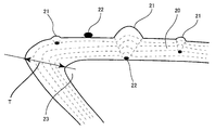
- FIG. 2 is a sectional view of an amorphous carbon coated plane 20 to show the growth of a macro-particle 21 .
- Amorphous carbon 20 is applied on a cutting edge 23 of a tool.
- Graphite particles 22 float and adhere to the coated plane during the process. Round particles 21 of various diameters can be observed at the surface through an SEM. However, such particles are not desirable in the present invention. It is assumed that graphite particles 22 are present at various thickness sites of amorphous carbon 20 as shown in FIG. 2 , since graphite particles 22 are scattered in the film deposition process.
- amorphous carbon film in order to improve the surface roughness of the amorphous carbon film, appropriate measures to prevent scattering of particles from the graphite material can be taken. For example, growing a film through low energy or using a filter by a magnetic field can be used.
- the surface roughness of the amorphous carbon film is desirably at least 0.002 ⁇ m and not more than 0.05 ⁇ m in Ra representation defined by the standards of JIS B0601. From the standpoint of a cutting tool, the surface roughness Ra should be as small as possible. In practice, a surface roughness Ra of zero cannot be achieved. It is found that the adhesion at the cutting edge is improved to increase the cutting performance when Ra is 0.05 ⁇ m or below as a result of various cutting experiments. Furthermore, the surface roughness is preferably at least 0.02 ⁇ m and not more than 0.5 ⁇ m in Ry representation defined by the standards of JIS B0601. If Ry exceeds 0.5 ⁇ m, any projection on the amorphous carbon film will become the adhesion origin of residuals to result in higher cutting resistance.
- the maximum film thickness of the amorphous carbon film at the cutting edge of a tool is set to 0.05 ⁇ m to 0.5 ⁇ m. If the maximum film thickness is less than 0.05 ⁇ m, the wear resistance is degraded. If the maximum film thickness exceeds 0.5 ⁇ m, the internal stress accumulated at the coated film will be increased to facilitate delamination, or cause chipping of the coated film. By setting the film thickness to not more than 0.5 ⁇ m, the size and density of the macro-particles at the surface can be reduced. There is the advantage that the surface roughness can be suppressed to not more than 0.05 ⁇ m in Ra representation and not more than 0.5 ⁇ m in Ry representation.
- the amorphous carbon film is thicker at the cutting edge of the tool as indicated by T in FIG. 2 .
- the performance is improved by reducing this thickness.
- the maximum thickness T at the cutting edge of the amorphous carbon film corresponding to cutting is preferably at least 0.05 ⁇ m and not more than 0.25 ⁇ m from the standpoint of lower adhesion.
- the Knoop hardness of the amorphous carbon film is preferably at least 20 GPa and not more than 50 GPa. If the hardness is lower than 20 GPa, the wear resistance is degraded. If the hardness exceeds 50 GPa, the chipping resistance at the cutting edge is reduced. Further preferably, the Knoop hardness of the amorphous carbon film is at least 25 GPa and not more than 40 GPa.
- FIG. 3 represents the Raman spectrum of the amorphous carbon of the present invention whereas FIG. 4 represents the Raman spectrum of conventional amorphous carbon that includes hydrogen.
- These spectra are obtained by Raman spectroscopic analysis using argon gas laser having a wavelength of 514.5 nm.
- the solid line indicates the measured result.
- a bulge is observed in the vicinity of 1340 cm ⁇ 1 .
- the background is removed from the spectral waveform.
- the spectrum with a bulge is formed by two Gaussian functions that are superimposed or added
- approximation is conducted by the nonlinear least-square method to obtain two separated peaks.
- the chain dotted line indicates the result.
- the height of the peak with the center about 1340 cm ⁇ 1 i.e indicated by I 1340 whereas the height of the peak about 1560 cm ⁇ 1 is indicated by I 1560 .
- a bulge in the vicinity of 1340 cm ⁇ 1 is not easily perceivable in the solid line.
- a total of three peaks are observed in the amorphous carbon film of the tool of the present invention according to FIG. 3 , i.e. from wave number 400 cm ⁇ 1 to 1000 cm ⁇ 1 , in the vicinity of 1340 cm ⁇ 1 , and in the vicinity of 1560 cm ⁇ 1 .
- no peak is observed at the lower wave number side of 400 cm ⁇ 1 to 1000 cm ⁇ 1 in the conventional coated film containing hydrogen according to FIG. 4 .
- the wear resistance is improved. It is possible that the film hardness is improved by the small-size sp 2 bond and the increase of sp 3 bond with distortion.
- the intensity ratio (S 700 /S 1340 ) of the integrated intensity of the peak located in the range from 400 cm ⁇ 1 to 1000 cm ⁇ 1 in wave number (S 700 )to the integrated intensity of the peak located in the vicinity of 1340 cm ⁇ 1 (S 1340 ) is preferably at least 0.01 and not more than 2.5. If the peak intensity ratio is less than 0.01, the wear resistance is equal to that of the conventional coated film. Although various film deposition experiments were carried out, a peak intensity ratio exceeding 2.5 could not be obtained by the experiments carried out, as will be described below.
- the intensity ratio (I 1340 /I 1560 ) of the peak intensity located in the vicinity of 1340 cm ⁇ 1 (I 1340 ) relative to the peak intensity located in the vicinity of 1560 cm ⁇ 1 (I 1560 ) is at least 0.1 and not more than 1.2, high wear resistance is exhibited.
- the ratio of the intensity (I 1340 ) of the peak located in the vicinity of 1340 cm ⁇ to the intensity (I 1560 ) of the peak located in the vicinity of 1560 cm ⁇ 1 is also interpreted as an sp 2 /sp 3 representing the presence of the carbon bond status in the coated film. Although these values of the peak intensity ratio do not directly indicate the contained amount of sp 2 , a relative classification of the coated film structure can be conducted.
- the hardness is increased when the intensity of the peak located in the vicinity of 1560 cm ⁇ 1 is high. In other words, the wear resistance is improved when the sp 3 bond characteristic is stronger.
- the intensity ratio (S 1340 /S 1560 ) of the integrated intensity of the peak located in the vicinity of 1340 cm ⁇ 1 (S 1340 ) to the integrated intensity of the peak located in the vicinity of 1560 cm ⁇ 1 (S 1560 ) is to be at least 0.3 and not more than 3.
- the peak located in the vicinity of 1560 cm ⁇ 1 is present in a range of at least 1560 cm ⁇ 1 and not more than 1580 cm ⁇ 1 , high wear resistance can be realized.
- the peak position in the Raman spectrum is affected by the stress in the coated film. In general, the peak in the Raman spectrum shifts to the higher wave number side when the stress in the coated film is high at the compressive side. In contrast, the peak in the Raman spectrum shifts to the lower wave number side when the stress in the coated film is high at the extension side. It was found that the wear resistance is improved when the stress in the coated film is high at the compressive side.
- the amorphous carbon film coated in conventional art is opaque in the visible region and has the color of brown to black.
- the amorphous carbon film of the tool of the present invention is transparent in the visible region, and exhibits interference color.
- Exhibiting interference color implies that sp 3 bond component in the amorphous carbon film is extremely great, and physical properties such as the refractive index, the optical bandgap and elastic modulus are closer to those of diamond than of the conventional amorphous carbon film.
- the amorphous carbon film of the present invention is used for the tool, superior wear resistance and heat resistance are exhibited due to the high film hardness. Since the WC base cemented carbide which is the base material of the tool of the present invention is silver or gray close to silver in color, the tool of the present invention is characterized in the appearance of exhibiting interference color.
- the interference color of the amorphous carbon film changes from ( 1 ) brown ⁇ ( 2 ) magenta ⁇ ( 3 ) violet ⁇ ( 4 ) blue-violet ⁇ ( 5 ) blue ⁇ ( 6 ) silver ⁇ ( 7 ) yellow ⁇ ( 8 ) red ⁇ ( 9 ) blue ⁇ ( 10 ) green ⁇ ( 11 ) yellow ⁇ ( 12 ) red, and then repeats the change from ( 8 ) red to ( 12 ) red thereafter, as a function of thicker film.
- the change of these colors is continuous with respect to difference in the film thickness. When the film is of a thickness intermediate therebetween, the color exhibited is the intermediate color therebetween.
- the inventors of the present invention studied the results and found that the coated film exhibited the colors between ( 2 ) magenta to ( 10 ) green when the range of 0.05 ⁇ m to 0.5 ⁇ m is selected for the maximum film thickness at the cutting edge of the tool.
- the color of the coated film may be the rainbow color corresponding to a plurality of color tones instead of a single color.
- the tool of the present invention may have a conventional amorphous carbon film of the brown to black color formed on the amorphous carbon film presenting the above-described interference colors.
- the tool of the present invention preferably has an interlayer provided between the base material and the amorphous carbon film to enhance the adherence of the amorphous carbon film.
- At least one type of element selected from the group consisting of an element from Groups IVa, Va, VIa and IIIb of the periodic table and from Group IVb of the periodic table excluding C, or carbide of at least one type of element selected from the group consisting of these elements is suitable.
- the interlayer includes at least one type of element selected from the group consisting of elements Ti, Zr, Hf, V, Nb, Ta, Cr, Mo, W and Si, or carbide of at least one type of element selected from the group consisting of these elements. Since these metal elements facilitate a strong bond with carbon, the formation of an amorphous carbon film on the interlayer of these metal elements or metal carbide produces stronger adherence.
- the thickness of the interlayer is at least 0.5 nm and less than 10 nm. If the film thickness is thinner than this range, the interlayer cannot play its role. If the thickness exceeds this range, adherence of only a level equal to that of conventional art can be obtained. By forming such an extremely thin interlayer, significant adherence not achieved in prior art can be obtained. Thus, the lifetime of the tool can be extremely improved.
- Adhesion can further be improved by providing a mixed composition layer whose composition of each coated film is mixed or a gradient composition layer whose composition is continuously varied between the interlayer and the amorphous carbon film.
- the mixed composition layer and the gradient composition layer are not necessarily distinguishable.
- the fabrication conditions are switched from those of forming an interlayer to those for forming an amorphous carbon film, mixture occurs of the compositions of the interlayer and the amorphous carbon layer, whereby a mixed composition layer or gradient composition layer is formed.
- XPS X-ray Photo-electronic Spectroscopy
- AES Alger Electron Spectroscopy
- the amorphous carbon coated tool of the present invention is particularly suitable for working on aluminum and alloy thereof by virtue of the wear resistance and adhesion resistance.
- the tool of the present invention is most suitable to be used on non-ferrous material such as titanium, magnesium and copper.
- the tool of the present invention is also effective for cutting materials including hard particles such as graphite, organic material, and working on printed circuit boards and bi-metallic cutting of iron type material and aluminum.
- the tool of the present invention can be used in working on steel such as stainless steel and cast metal in addition to non-ferrous material by virtue of the high hardness of the amorphous carbon film.
- the amorphous carbon coated tool of the present invention can be used in an application including one type selected from the group consisting of a drill, an end mill, an indexable insert for end mill working, an indexable insert for a milling cutter, an indexable insert for a turning tool, a metal saw, a gear cutter, a reamer and a tap.
- a ⁇ 8 mm drill made of WC base cemented carbide was prepared.
- This base includes 1% by mass of (Ta, Nb) C, and Co of a content indicated in Table 1 that will be described afterwards.
- the surface of this base was subjected to the well-known cathode arc ion plating method, whereby Samples 1-38 of amorphous carbon coated drills of the present invention shown in Table 1-Table 4 were prepared.
- a plurality of targets 2 and 3 are disposed in a film deposition apparatus 1 .
- a drill formed of cemented carbide is attached to a base holder 4 that rotates between targets about the center point of respective targets.
- Power supplies 7 and 8 are adjusted to alter the discharging current of the cathode to coat amorphous carbon while controlling the vaporization of the target material.
- the vacuum level in deposition apparatus 1 was set to an atmosphere of 2 ⁇ 10 ⁇ 3 Pa while heating up to 100° C. using a base heater 6 .
- Argon gas is then introduced.
- a voltage of ⁇ 1000V is applied to base holder 4 through a bias power supply 9 while maintaining the atmosphere at 2 ⁇ 10 ⁇ 1 Pa.
- the argon gas is discharged.
- the gas is introduced into deposition apparatus 1 through an inlet 10 and output through an outlet 11 .
- the voltage from the bias power supply 9 was set to—several hundred V.
- the temperature of the base material was set up in 100° C.
- a target selected from the group consisting of an element from Groups IVa, Va, VIa and IIIb of the periodic table and an element of Group IVb of the periodic table excluding C was vaporized and ionized, with or without hydrocarbon gas introduced, and a voltage of—several hundred V was applied to base holder 4 by bias power supply 9 .
- an interlayer of this metal or of metal carbide was formed.
- the formation of an amorphous carbon film from an interlayer was effected by switching the target and atmosphere. At the time of this switching, slight mixture of the components of both layers generally occurs. It is therefore presumed that a mixed composition layer or gradient composition layer of the source material is present between the layers.
- Comparative Example 4 an amorphous carbon film was deposited at the surface of a cemented carbide drill identical to that described above using a general plasma CVD.
- composition of A5052 in Table 7 is defined in the standards of JIS H4000.
- the surface of a ⁇ 4 mm reamer made of cemented carbide was coated with an amorphous carbon film (film of Sample 2).
- the cemented carbide base of Example 2 includes 1% by mass of (Ta, Nb) C, and 7% by mass of Co.
- the hydrogen content in the amorphous carbon film is not more than 5 atomic %.
- a hydrogenated amorphous carbon film by CVD (Comparative Example 4), a TiN film (Comparative Example 5) and a TiAlN film (Comparative Example 6) were deposited.
- Each of the surface coated reamers fabricated by the above-described method were used in the boring process of an aluminium die cast (ADC12) under the conditions shown in Table 8. The number of bores produced and the status of the cutting edge were evaluated.
- composition of ADC12 in Table 8 is defined in the standards of JIS H5302.
- the surface of a ⁇ 7 mm end mill made of cemented carbide was coated with an amorphous carbon film (film of Sample 3 of the present invention), fabricated by a method identical to that of Example 1.
- the cemented carbide base contains 1% by mass of (Ta, Nb) C and 7% by mass of Co.
- the hydrogen content in the amorphous carbon film is not more than 5 atomic %.
- a hydrogenated amorphous carbon film by CVD (Comparative Example 4), a TiN film (Comparative Example 5), and a TiAlN film (Comparative Example 6) were deposited.
- Ad axial depth of cut
- Rd radial depth of cut
- composition of ADC12 in Table 9 is defined in the standards of JIS H5302.
- the hydrogenated amorphous carbon film by CVD (Comparative Example 4) and the metal nitride films formed by PVD (Comparative Examples 5 and 6) exhibited deviation from the tolerance in surface roughness at 20 m, 5 m and 6 m, respectively. Therefore, determination was made that the lifetime of these tools has expired. Aluminum adhering to the leading edges of the surface coated end mills that had expired lifetime was removed and studied. It was found that the coated film is no longer present, and the WC base cemented carbide of the base was exposed.
- the back side of an indexable insert was coated with an amorphous carbon film (coated film of Sample 2 of present invention) according to a method identical to that of EXAMPLE 1.
- the cemented base included 1% by mass of (Ta, Nb) C and 6% by mass of Co.
- the hydrogen content in the amorphous carbon film was not more than 5 atomic %.
- a hydrogenated amorphous carbon film by CVD (Comparative Example 4), TiN film (Comparative Example 5) and TiAlN film (Comparative Example 6) were coated.
- Each of the surface coated indexable insert 1 fabricated by the above-described method was attached to a holder having a tool diameter of 32 mm and used for an end mill process on an aluminium die cast (A390) under the conditions shown in Table 10.
- the cutting length and status of the cutting edge before the surface roughness of the workpiece deviated from the tolerance were evaluated.
- Ad axial depth of cut
- Rd radial depth of cut
- A390 in Table 10 has the composition of Al-16 ⁇ 18% (m/m) Si.
- the surface roughness of the hydrogen amorphous carbon film by CVD (Comparative Example 4), and the metal nitride film formed by PVD (Comparative Examples 5 and 6) deviated from the surface roughness tolerance at 15 m, 4 m and 2 m, respectively. Accordingly, determination was made that the lifetime of the tools has expired. Aluminum adhering to the tip of the surface coated insert determined as having expired lifetime was removed and examined. It was found that the coated film is no longer present and the WC base cemented carbide of the base was exposed.
- the end mill of Sample 2 of the present invention exhibited deviation in the surface roughness tolerance of the workpiece when cutting has been effected for 900 m. Accordingly, determination was made that the lifetime of that tool has expired when the length of 900 m has been cut.
- the tool of the present invention maintains wear resistance and exhibits superior adhesion resistance.
- the cutting and wear resistance of the tool of the present invention can be greatly increased.
- an amorphous carbon film absent of hydrogen the wear resistance and adhesion resistance can further be improved.
Landscapes
- Chemical & Material Sciences (AREA)
- Engineering & Computer Science (AREA)
- Mechanical Engineering (AREA)
- Chemical Kinetics & Catalysis (AREA)
- Materials Engineering (AREA)
- Metallurgy (AREA)
- Organic Chemistry (AREA)
- Cutting Tools, Boring Holders, And Turrets (AREA)
- Physical Vapour Deposition (AREA)
- Drilling Tools (AREA)
Applications Claiming Priority (2)
| Application Number | Priority Date | Filing Date | Title |
|---|---|---|---|
| JP2001178832 | 2001-06-13 | ||
| JP2001-178832(P) | 2001-06-13 |
Publications (2)
| Publication Number | Publication Date |
|---|---|
| US20030049083A1 US20030049083A1 (en) | 2003-03-13 |
| US6881475B2 true US6881475B2 (en) | 2005-04-19 |
Family
ID=19019473
Family Applications (1)
| Application Number | Title | Priority Date | Filing Date |
|---|---|---|---|
| US10/167,770 Expired - Lifetime US6881475B2 (en) | 2001-06-13 | 2002-06-11 | Amorphous carbon coated tool and fabrication method thereof |
Country Status (5)
| Country | Link |
|---|---|
| US (1) | US6881475B2 (de) |
| EP (1) | EP1266979B1 (de) |
| KR (1) | KR100501860B1 (de) |
| CN (1) | CN1291809C (de) |
| IL (1) | IL150195A0 (de) |
Cited By (20)
| Publication number | Priority date | Publication date | Assignee | Title |
|---|---|---|---|---|
| US20030118412A1 (en) * | 2001-12-26 | 2003-06-26 | Sumitomo Electric Industries, Ltd. | Surface-coated machining tools |
| US20040258493A1 (en) * | 2003-06-19 | 2004-12-23 | Osg Corporation | Tap having threaded portion coated with diamond-like carbon coating |
| US20060046060A1 (en) * | 2004-08-26 | 2006-03-02 | Ina Schaeffler Kg | Wear-resistant coating and process for producing it |
| US20060154109A1 (en) * | 2004-12-22 | 2006-07-13 | Sandvik Intellectual Property Ab | Tool holders for chip removing machining |
| US20060154051A1 (en) * | 2004-12-22 | 2006-07-13 | Sandvik Intellectual Property Ab | Coated cutting inserts |
| US20070059529A1 (en) * | 2005-09-10 | 2007-03-15 | Hosenfeldt Tim M | Wear-resistant coating and process for producing it |
| US20070254187A1 (en) * | 2006-04-27 | 2007-11-01 | Kabushiki Kaisha Kobe Seiko Sho (Kobe Steel, Ltd) | Amorphous-carbon-based hard multilayer film and hard surface member having the film on surface |
| US20090098361A1 (en) * | 2006-02-10 | 2009-04-16 | Takayasu Sato | Member for cavitation erosion resistance and method for manufacturing same |
| AU2007211901B2 (en) * | 2007-08-23 | 2010-02-18 | Sandvik Intellectual Property Ab | A reamer |
| US20100196109A1 (en) * | 2007-06-26 | 2010-08-05 | Nanofilm Technologies International Pte Ltd | Cutting tools having plasma deposited carbon coatings |
| US20100247885A1 (en) * | 2009-03-24 | 2010-09-30 | Kabushiki Kaisha Kobe Seiko Sho(Kobe Steel, Ltd.) | Laminated film and laminated film-coated member |
| CN102259206A (zh) * | 2010-05-25 | 2011-11-30 | 中国砂轮企业股份有限公司 | 镀膜微钻针、其制备方法及使用其的钻孔方法 |
| US20120213601A1 (en) * | 2010-09-07 | 2012-08-23 | Sumitomo Electric Hardmetal Corp. | Cutting tool |
| US20150017468A1 (en) * | 2013-07-15 | 2015-01-15 | GM Global Technology Operations LLC | Coated tool and methods of making and using the coated tool |
| US20150167170A1 (en) * | 2013-12-12 | 2015-06-18 | The Boeing Company | Gradient thin films |
| US20160375497A1 (en) * | 2013-11-29 | 2016-12-29 | Mitsubishi Materials Corporation | Cutting tool made of diamond-coated cemented carbide and method for producing the same |
| US20170141486A1 (en) * | 2014-06-25 | 2017-05-18 | Yazaki Corporation | Electric wire with terminal |
| US10392576B2 (en) * | 2014-09-16 | 2019-08-27 | Kabushiki Kaisha Riken | Coated sliding member |
| US10428416B2 (en) * | 2014-09-17 | 2019-10-01 | Nippon Itf, Inc. | Coating film, manufacturing method for same, and PVD device |
| US11041245B2 (en) | 2016-05-20 | 2021-06-22 | Fuji Kihan Co., Ltd. | Method for preventing adhesion of aluminum |
Families Citing this family (32)
| Publication number | Priority date | Publication date | Assignee | Title |
|---|---|---|---|---|
| US7147413B2 (en) * | 2003-02-27 | 2006-12-12 | Kennametal Inc. | Precision cemented carbide threading tap |
| US7147939B2 (en) | 2003-02-27 | 2006-12-12 | Kennametal Inc. | Coated carbide tap |
| DE112005003529T5 (de) * | 2005-04-04 | 2008-05-15 | Osg Corporation, Toyokawa | Bohrer |
| JP5165484B2 (ja) * | 2008-07-16 | 2013-03-21 | ユニタック株式会社 | ドリルヘッドの製作方法及びドリルヘッド |
| CN101554790B (zh) * | 2009-05-18 | 2012-07-04 | 浙江大学 | 一种超硬碳薄膜及其制备方法 |
| JP5351618B2 (ja) * | 2009-06-05 | 2013-11-27 | 株式会社神戸製鋼所 | リチウムイオン二次電池用負極材、および、その製造方法、ならびに、リチウムイオン二次電池 |
| JP5330903B2 (ja) * | 2009-06-08 | 2013-10-30 | 株式会社神戸製鋼所 | リチウムイオン二次電池用負極材、および、その製造方法、ならびに、リチウムイオン二次電池 |
| JP4782222B2 (ja) * | 2009-08-03 | 2011-09-28 | ユニオンツール株式会社 | 穴明け工具用非晶質炭素皮膜及び穴明け工具 |
| CN103052456B (zh) * | 2010-08-04 | 2015-04-22 | 株式会社图格莱 | 被覆工具 |
| RU2486995C2 (ru) * | 2011-10-03 | 2013-07-10 | Российская Федерация, от имени которой выступает Министерство промышленности и торговли Российской Федерации (Минпромторг России) | Способ получения композиционного катода |
| CN103088303A (zh) * | 2013-01-17 | 2013-05-08 | 西安交通大学 | 一种钛金属加工用丝锥表面制备非晶碳涂层的方法 |
| RU2527113C1 (ru) * | 2013-03-04 | 2014-08-27 | Игорь Валерьевич Белашов | Способ нанесения аморфного алмазоподобного покрытия на лезвия хирургических скальпелей |
| JP5974940B2 (ja) * | 2013-03-14 | 2016-08-23 | 三菱マテリアル株式会社 | 交換式切削ヘッド |
| JP6211987B2 (ja) * | 2014-04-22 | 2017-10-11 | 株式会社神戸製鋼所 | Znめっき鋼板の熱間成形用金型 |
| JP2016056435A (ja) * | 2014-09-12 | 2016-04-21 | 株式会社神戸製鋼所 | 硬質摺動部材の製造方法、および硬質摺動部材 |
| CN105598457B (zh) * | 2016-02-17 | 2017-12-01 | 刘三光 | 一种手术刀刀片及其制备方法 |
| CN108884550B (zh) * | 2016-03-01 | 2022-08-30 | 欧瑞康表面处理解决方案股份公司普费菲孔 | 具有锆附着层的无氢碳涂层 |
| JP6534123B2 (ja) * | 2016-03-23 | 2019-06-26 | 日本アイ・ティ・エフ株式会社 | 被覆膜とその製造方法およびpvd装置 |
| WO2018112910A1 (zh) * | 2016-12-23 | 2018-06-28 | 深圳市金洲精工科技股份有限公司 | 一种刀具复合涂层、刀具和刀具复合涂层的制备方法 |
| KR102079778B1 (ko) * | 2017-12-14 | 2020-02-21 | 한국생산기술연구원 | 스퍼터링 지그 |
| CN109023365B (zh) * | 2018-08-10 | 2020-05-26 | 广东省新材料研究所 | 一种唇型油封旋转轴耐磨减摩复合涂层及其制备方法 |
| JP7227089B2 (ja) * | 2019-06-28 | 2023-02-21 | 株式会社ダイヤメット | 切削工具およびその表面保護皮膜の形成に使用する素材 |
| US20220088806A1 (en) * | 2019-07-03 | 2022-03-24 | Ngk Spark Plug Co., Ltd. | Kitchen knife and blade |
| CN114207178B (zh) * | 2019-07-31 | 2024-06-04 | 欧瑞康表面处理解决方案股份公司普费菲孔 | 涂覆于基材上的梯级无氢碳基硬材料层 |
| US11992882B2 (en) | 2020-04-24 | 2024-05-28 | Sumitomo Electric Hardmetal Corp. | Cutting tool |
| JP7067690B2 (ja) * | 2020-04-24 | 2022-05-16 | 住友電工ハードメタル株式会社 | 切削工具 |
| JP7023388B1 (ja) | 2020-04-24 | 2022-02-21 | 住友電工ハードメタル株式会社 | 切削工具 |
| CN111850484B (zh) * | 2020-07-24 | 2022-05-17 | 太原理工大学 | 一种制备强韧化非晶碳基多相杂化薄膜的装置及方法 |
| CN116887936B (zh) * | 2021-06-02 | 2026-04-07 | 住友电工硬质合金株式会社 | 切削工具 |
| CN113996825B (zh) * | 2021-12-08 | 2023-08-29 | 广东工业大学 | 一种多切削刃刀具以及非晶合金高效切削方法 |
| WO2024008903A1 (en) | 2022-07-06 | 2024-01-11 | Oerlikon Surface Solutions Ag, Pfäffikon | Metal free coating comprising tetrahedral hydrogen-free amorphous carbon |
| TWI895774B (zh) * | 2023-08-02 | 2025-09-01 | 尖點科技股份有限公司 | 鑽頭表面改質構造及其加工方法 |
Citations (24)
| Publication number | Priority date | Publication date | Assignee | Title |
|---|---|---|---|---|
| US4842937A (en) * | 1987-02-27 | 1989-06-27 | Ernst Winter & Sohn (Gmbh & Co.) | Method of depositing a wear-protective layer on a cutting tool and wear protective layer produced by the method |
| JPH01252752A (ja) | 1988-03-31 | 1989-10-09 | Mitsubishi Metal Corp | 炭化タングステン基超硬合金製エンドミル |
| EP0561641A1 (de) * | 1992-03-20 | 1993-09-22 | Komag, Inc. | Verfahren zum Anbringen eines Kohlenstoffschutzfilms auf eine Magnetplatte durch Kathodenzerstäubung mit einer eine Gleichstromvorspannung überlagernden Wechselspannung |
| JPH0718415A (ja) | 1993-06-30 | 1995-01-20 | Mitsubishi Materials Corp | 硬質被覆層がすぐれた密着性を有する表面被覆立方晶窒化ほう素基セラミックス製切削工具 |
| JPH0785465A (ja) | 1993-09-20 | 1995-03-31 | Tosoh Corp | 磁気ディスクの製造方法 |
| JPH07192254A (ja) | 1993-12-28 | 1995-07-28 | Hitachi Ltd | 磁気ディスクおよびその製造方法 |
| US5474816A (en) | 1993-04-16 | 1995-12-12 | The Regents Of The University Of California | Fabrication of amorphous diamond films |
| US5482602A (en) | 1993-11-04 | 1996-01-09 | United Technologies Corporation | Broad-beam ion deposition coating methods for depositing diamond-like-carbon coatings on dynamic surfaces |
| JPH08119774A (ja) | 1994-10-27 | 1996-05-14 | Sumitomo Electric Ind Ltd | 工具用複合高硬度材料 |
| EP0724023A1 (de) * | 1995-01-27 | 1996-07-31 | Fraunhofer-Gesellschaft Zur Förderung Der Angewandten Forschung E.V. | Harte, amorphe, wasserstoffreie C-Schichten |
| US5562982A (en) * | 1992-09-30 | 1996-10-08 | Matsushita Electric Industrial Co., Ltd. | Magnetic recording medium |
| US5567512A (en) * | 1993-10-08 | 1996-10-22 | Hmt Technology Corporation | Thin carbon overcoat and method of its making |
| JPH09314405A (ja) | 1996-05-31 | 1997-12-09 | Kyocera Corp | 被覆切削工具 |
| JPH1025565A (ja) | 1996-07-12 | 1998-01-27 | Osamu Takai | 硬質薄膜の製造方法および硬質薄膜 |
| US5733668A (en) | 1992-10-26 | 1998-03-31 | Kabushiki Kaisha Kobe Seiko Sho | Method for the preparation of WC-Co Alloys and hard carbon-layer coated on WC-Co Alloys, and their coated tools |
| JPH1118809A (ja) | 1997-06-30 | 1999-01-26 | Kyocera Corp | 装飾部材 |
| JPH1186275A (ja) | 1997-09-12 | 1999-03-30 | Sony Corp | 磁気記録媒体 |
| JP2000176705A (ja) | 1998-12-09 | 2000-06-27 | Nachi Fujikoshi Corp | 硬質炭素系被膜を有する工具部材 |
| US6110329A (en) | 1996-06-25 | 2000-08-29 | Forschungszentrum Karlsruhe Gmbh | Method of manufacturing a composite material |
| US6139964A (en) * | 1991-04-22 | 2000-10-31 | Multi-Arc Inc. | Plasma enhancement apparatus and method for physical vapor deposition |
| EP1067211A1 (de) | 1999-07-08 | 2001-01-10 | Sumitomo Electric Industries, Ltd. | Harte Beschichtung und beschichteter Bauteil |
| JP2001062605A (ja) | 1999-08-30 | 2001-03-13 | Sumitomo Electric Ind Ltd | 非晶質カーボン被覆工具 |
| US6284376B1 (en) | 1997-07-31 | 2001-09-04 | Kyocera Corporation | Ornamental article and process for producing the same |
| US6726993B2 (en) * | 1997-12-02 | 2004-04-27 | Teer Coatings Limited | Carbon coatings, method and apparatus for applying them, and articles bearing such coatings |
-
2002
- 2002-06-11 US US10/167,770 patent/US6881475B2/en not_active Expired - Lifetime
- 2002-06-12 KR KR10-2002-0032713A patent/KR100501860B1/ko not_active Expired - Lifetime
- 2002-06-12 IL IL15019502A patent/IL150195A0/xx active IP Right Grant
- 2002-06-13 CN CNB021227888A patent/CN1291809C/zh not_active Expired - Lifetime
- 2002-06-13 EP EP02254150.2A patent/EP1266979B1/de not_active Expired - Lifetime
Patent Citations (26)
| Publication number | Priority date | Publication date | Assignee | Title |
|---|---|---|---|---|
| US4842937A (en) * | 1987-02-27 | 1989-06-27 | Ernst Winter & Sohn (Gmbh & Co.) | Method of depositing a wear-protective layer on a cutting tool and wear protective layer produced by the method |
| JPH01252752A (ja) | 1988-03-31 | 1989-10-09 | Mitsubishi Metal Corp | 炭化タングステン基超硬合金製エンドミル |
| US6139964A (en) * | 1991-04-22 | 2000-10-31 | Multi-Arc Inc. | Plasma enhancement apparatus and method for physical vapor deposition |
| EP0561641A1 (de) * | 1992-03-20 | 1993-09-22 | Komag, Inc. | Verfahren zum Anbringen eines Kohlenstoffschutzfilms auf eine Magnetplatte durch Kathodenzerstäubung mit einer eine Gleichstromvorspannung überlagernden Wechselspannung |
| US5562982A (en) * | 1992-09-30 | 1996-10-08 | Matsushita Electric Industrial Co., Ltd. | Magnetic recording medium |
| US5733668A (en) | 1992-10-26 | 1998-03-31 | Kabushiki Kaisha Kobe Seiko Sho | Method for the preparation of WC-Co Alloys and hard carbon-layer coated on WC-Co Alloys, and their coated tools |
| US5763087A (en) | 1993-04-16 | 1998-06-09 | Regents Of The University Of California | Amorphous diamond films |
| US5474816A (en) | 1993-04-16 | 1995-12-12 | The Regents Of The University Of California | Fabrication of amorphous diamond films |
| JPH0718415A (ja) | 1993-06-30 | 1995-01-20 | Mitsubishi Materials Corp | 硬質被覆層がすぐれた密着性を有する表面被覆立方晶窒化ほう素基セラミックス製切削工具 |
| JPH0785465A (ja) | 1993-09-20 | 1995-03-31 | Tosoh Corp | 磁気ディスクの製造方法 |
| US5567512A (en) * | 1993-10-08 | 1996-10-22 | Hmt Technology Corporation | Thin carbon overcoat and method of its making |
| US5482602A (en) | 1993-11-04 | 1996-01-09 | United Technologies Corporation | Broad-beam ion deposition coating methods for depositing diamond-like-carbon coatings on dynamic surfaces |
| JPH07192254A (ja) | 1993-12-28 | 1995-07-28 | Hitachi Ltd | 磁気ディスクおよびその製造方法 |
| JPH08119774A (ja) | 1994-10-27 | 1996-05-14 | Sumitomo Electric Ind Ltd | 工具用複合高硬度材料 |
| EP0724023A1 (de) * | 1995-01-27 | 1996-07-31 | Fraunhofer-Gesellschaft Zur Förderung Der Angewandten Forschung E.V. | Harte, amorphe, wasserstoffreie C-Schichten |
| JPH09314405A (ja) | 1996-05-31 | 1997-12-09 | Kyocera Corp | 被覆切削工具 |
| US6110329A (en) | 1996-06-25 | 2000-08-29 | Forschungszentrum Karlsruhe Gmbh | Method of manufacturing a composite material |
| JPH1025565A (ja) | 1996-07-12 | 1998-01-27 | Osamu Takai | 硬質薄膜の製造方法および硬質薄膜 |
| JPH1118809A (ja) | 1997-06-30 | 1999-01-26 | Kyocera Corp | 装飾部材 |
| US6284376B1 (en) | 1997-07-31 | 2001-09-04 | Kyocera Corporation | Ornamental article and process for producing the same |
| JPH1186275A (ja) | 1997-09-12 | 1999-03-30 | Sony Corp | 磁気記録媒体 |
| US6110584A (en) * | 1997-09-12 | 2000-08-29 | Sony Corporation | Magnetic recording medium |
| US6726993B2 (en) * | 1997-12-02 | 2004-04-27 | Teer Coatings Limited | Carbon coatings, method and apparatus for applying them, and articles bearing such coatings |
| JP2000176705A (ja) | 1998-12-09 | 2000-06-27 | Nachi Fujikoshi Corp | 硬質炭素系被膜を有する工具部材 |
| EP1067211A1 (de) | 1999-07-08 | 2001-01-10 | Sumitomo Electric Industries, Ltd. | Harte Beschichtung und beschichteter Bauteil |
| JP2001062605A (ja) | 1999-08-30 | 2001-03-13 | Sumitomo Electric Ind Ltd | 非晶質カーボン被覆工具 |
Non-Patent Citations (10)
| Title |
|---|
| B. F. Coll et al., "Diamond-Like Carbon Films Synthesized by Cathodic Arc Evaporation", Thin Solid Films, Elsevier-Sequoia S. A. Lausanne, CH., vol. 209, No. 2, Mar. 30, 1992; pp. 165-173 XP000362002, ISSN: 0040-6090. |
| English Translation (computer-generated) of JP 2001-062605, published Mar. 13, 2001. |
| J. Ullman, "Low Energy Ion Assisted Carbon Film Growth: Methods and Mechanisms", Nuclear Instruments & Methods in Physics Research, Section-B: Beam Interactions With Materials and Atoms, North-Holland Publishing Company, Amsterdam, NL, vol. 127-128, May 1, 1997, pp. 910-917, XP004096874, ISSN: 0168-583X. |
| J.P. Hirvonen et al.; "Characterization and Unlubricated Sliding of Ion-Beam-Deposited Hydrogen-Free Diamond-Like Carbon Films", Wear, Lausanne, CH. vol. 141, 1990, pp. 45-58, XP000570574. |
| Lifshitz "Hydrogen free amorphous carbon films: correlation between growth conditions and properties" Diamond and Related Materials 5 (1996) 388-400. |
| M. Bonelli et al., "Structural and mechanical properties of ta-C films grown by pulsed laser deposition", Europhysics Letters, May 15, 2000, Eur. Phys. Soc. by EDP Sciences and Soc. Italiana Fisica, France, vol. 50, No. 4, pp. 501-506, XP008027117, ISSN: 0295-5075. |
| M. Hakovirta, "Hardmetal Woodcutting Tool Tips Coated With Tetrahedral Amorphous Carbon", Diamond and Related Materials, Elsevier Science Publishers, Amsterdam, NL., vol. 8, No. 7, Jul. 1999, pp. 1225-1228, XP004253920, ISSN: 0925-9635. |
| R. Kalish et al., "Thermal Stability and Relaxation In Diamond-Like-Carbon. A Raman Study of Films with Different SP3 Fractions (TA-C to A-C)", Applied Physics Letters, American Institute of Physics, New York, US, vol. 74, No. 20, May 17, 1999, pp. 2936-2938, XP00083705, ISSN: 0003-6951. |
| S. Santavirta et al., "Some Relevant Issues Related to the Use of Amorphous Diamond Coatings for Medical Applications", Diamond and Related Materials, Elsevier Science Publishers, Amsterdam, NL, vol. 7, No. 2-5, Feb. 1, 1998, pp. 482-485, XP004115090, ISSN: 095-9635. |
| Y. Lifshitz, "Diamond-like Carbon-Present Status", Diamond and Related Materials, Elsevier Science Publishers, Amsterdam, NL., vol. 8, No. 8-9, Aug. 1999, pp. 1659-1676, XP004254004, ISSN: 0925-9635. |
Cited By (31)
| Publication number | Priority date | Publication date | Assignee | Title |
|---|---|---|---|---|
| US20030118412A1 (en) * | 2001-12-26 | 2003-06-26 | Sumitomo Electric Industries, Ltd. | Surface-coated machining tools |
| US7732066B2 (en) * | 2001-12-26 | 2010-06-08 | Sumitomo Electric Industries, Ltd. | Surface-coated machining tools |
| US20040258493A1 (en) * | 2003-06-19 | 2004-12-23 | Osg Corporation | Tap having threaded portion coated with diamond-like carbon coating |
| US20080044646A1 (en) * | 2004-08-26 | 2008-02-21 | Ina Schaeffler Kg | Wear-resistant coating and process for producing it |
| US20060046060A1 (en) * | 2004-08-26 | 2006-03-02 | Ina Schaeffler Kg | Wear-resistant coating and process for producing it |
| US7964295B2 (en) * | 2004-12-22 | 2011-06-21 | Sandvik Intellectual Property Ab | Coated cutting inserts |
| US20060154051A1 (en) * | 2004-12-22 | 2006-07-13 | Sandvik Intellectual Property Ab | Coated cutting inserts |
| US20060154109A1 (en) * | 2004-12-22 | 2006-07-13 | Sandvik Intellectual Property Ab | Tool holders for chip removing machining |
| US20070059529A1 (en) * | 2005-09-10 | 2007-03-15 | Hosenfeldt Tim M | Wear-resistant coating and process for producing it |
| US8039108B2 (en) * | 2006-02-10 | 2011-10-18 | Toyota Jidosha Kabushiki Kaisha | Member for cavitation erosion resistance and method for manufacturing same |
| US20090098361A1 (en) * | 2006-02-10 | 2009-04-16 | Takayasu Sato | Member for cavitation erosion resistance and method for manufacturing same |
| US20070254187A1 (en) * | 2006-04-27 | 2007-11-01 | Kabushiki Kaisha Kobe Seiko Sho (Kobe Steel, Ltd) | Amorphous-carbon-based hard multilayer film and hard surface member having the film on surface |
| US7887919B2 (en) * | 2006-04-27 | 2011-02-15 | Kobe Steel, Ltd. | Amorphous-carbon-based hard multilayer film and hard surface member having the film on surface |
| US20100196109A1 (en) * | 2007-06-26 | 2010-08-05 | Nanofilm Technologies International Pte Ltd | Cutting tools having plasma deposited carbon coatings |
| CN101743083B (zh) * | 2007-06-26 | 2012-03-21 | 纳峰科技私人有限公司 | 具有等离子体沉积的碳涂层的切削工具 |
| AU2007211901B2 (en) * | 2007-08-23 | 2010-02-18 | Sandvik Intellectual Property Ab | A reamer |
| US20100247885A1 (en) * | 2009-03-24 | 2010-09-30 | Kabushiki Kaisha Kobe Seiko Sho(Kobe Steel, Ltd.) | Laminated film and laminated film-coated member |
| US8574715B2 (en) * | 2009-03-24 | 2013-11-05 | Kobe Steel, Ltd. | Laminated film and laminated film-coated member |
| CN102259206A (zh) * | 2010-05-25 | 2011-11-30 | 中国砂轮企业股份有限公司 | 镀膜微钻针、其制备方法及使用其的钻孔方法 |
| US20120213601A1 (en) * | 2010-09-07 | 2012-08-23 | Sumitomo Electric Hardmetal Corp. | Cutting tool |
| US9186728B2 (en) * | 2010-09-07 | 2015-11-17 | Sumitomo Electric Hardmetal Corp. | Cutting tool |
| US20150017468A1 (en) * | 2013-07-15 | 2015-01-15 | GM Global Technology Operations LLC | Coated tool and methods of making and using the coated tool |
| US9371576B2 (en) * | 2013-07-15 | 2016-06-21 | GM Global Technology Operations LLC | Coated tool and methods of making and using the coated tool |
| US20160375497A1 (en) * | 2013-11-29 | 2016-12-29 | Mitsubishi Materials Corporation | Cutting tool made of diamond-coated cemented carbide and method for producing the same |
| US10086438B2 (en) * | 2013-11-29 | 2018-10-02 | Mitsubishi Materials Corporation | Cutting tool made of diamond-coated cemented carbide and method for producing the same |
| US20150167170A1 (en) * | 2013-12-12 | 2015-06-18 | The Boeing Company | Gradient thin films |
| US9139908B2 (en) * | 2013-12-12 | 2015-09-22 | The Boeing Company | Gradient thin films |
| US20170141486A1 (en) * | 2014-06-25 | 2017-05-18 | Yazaki Corporation | Electric wire with terminal |
| US10392576B2 (en) * | 2014-09-16 | 2019-08-27 | Kabushiki Kaisha Riken | Coated sliding member |
| US10428416B2 (en) * | 2014-09-17 | 2019-10-01 | Nippon Itf, Inc. | Coating film, manufacturing method for same, and PVD device |
| US11041245B2 (en) | 2016-05-20 | 2021-06-22 | Fuji Kihan Co., Ltd. | Method for preventing adhesion of aluminum |
Also Published As
| Publication number | Publication date |
|---|---|
| EP1266979B1 (de) | 2014-04-02 |
| EP1266979A3 (de) | 2004-03-31 |
| KR20020094902A (ko) | 2002-12-18 |
| IL150195A0 (en) | 2002-12-01 |
| CN1291809C (zh) | 2006-12-27 |
| CN1390667A (zh) | 2003-01-15 |
| US20030049083A1 (en) | 2003-03-13 |
| KR100501860B1 (ko) | 2005-07-20 |
| EP1266979A2 (de) | 2002-12-18 |
Similar Documents
| Publication | Publication Date | Title |
|---|---|---|
| US6881475B2 (en) | Amorphous carbon coated tool and fabrication method thereof | |
| US6962751B2 (en) | Amorphous carbon coated tools and method of producing the same | |
| EP1710326B1 (de) | Oberflächenbeschichtetes schneidwerkzeug | |
| KR101635488B1 (ko) | 절삭 공구 | |
| US5656383A (en) | Coated member having excellent hardness and, adhesive properties | |
| RU2528930C2 (ru) | Покрывная система, деталь с покрытием и способ ее получения | |
| US8945251B2 (en) | Cutting tool | |
| US20090252973A1 (en) | Coated body | |
| JP4018480B2 (ja) | 被覆硬質工具 | |
| KR101004277B1 (ko) | 표면 피복 절삭 공구 | |
| KR101505222B1 (ko) | 다층 금속 산화물 코팅을 구비한 공구 및 코팅된 공구의 제조 방법 | |
| JP3719709B2 (ja) | 非晶質カーボン被覆工具およびその製造方法 | |
| JP3718664B2 (ja) | 非晶質カーボン被覆工具およびその製造方法 | |
| JP2005022073A (ja) | Dlc被覆工具 | |
| JP2009061540A (ja) | 非晶質炭素膜被覆工具 | |
| JP3719708B2 (ja) | 非晶質カーボン被覆工具およびその製造方法 | |
| JP4445815B2 (ja) | 表面被覆切削工具 | |
| JP3963810B2 (ja) | 非晶質カーボン被覆工具およびその製造方法 | |
| JP3586218B2 (ja) | 被覆切削工具 | |
| CN112262006A (zh) | 切削工具 | |
| JP4456905B2 (ja) | 表面被覆切削工具 | |
| CN112262007A (zh) | 切削工具 | |
| JP2003025112A (ja) | 切粉に対する表面潤滑性にすぐれた表面被覆超硬合金製切削工具 | |
| CN117561134A (zh) | 涂层刀具及切削刀具 | |
| JP2009061539A (ja) | 非晶質炭素膜被覆工具 |
Legal Events
| Date | Code | Title | Description |
|---|---|---|---|
| AS | Assignment |
Owner name: NISSIN ELECTRIC CO., LTD., JAPAN Free format text: ASSIGNMENT OF ASSIGNORS INTEREST;ASSIGNORS:OHTANI, SATOSHI;OKAZAKI, NAOTO;OGATA, KIYOSHI;AND OTHERS;REEL/FRAME:013148/0181;SIGNING DATES FROM 20020710 TO 20020715 Owner name: SUMITOMO ELECTRIC INDUSTRIES, LTD., JAPAN Free format text: ASSIGNMENT OF ASSIGNORS INTEREST;ASSIGNORS:OHTANI, SATOSHI;OKAZAKI, NAOTO;OGATA, KIYOSHI;AND OTHERS;REEL/FRAME:013148/0181;SIGNING DATES FROM 20020710 TO 20020715 |
|
| STCF | Information on status: patent grant |
Free format text: PATENTED CASE |
|
| CC | Certificate of correction | ||
| FEPP | Fee payment procedure |
Free format text: PAYOR NUMBER ASSIGNED (ORIGINAL EVENT CODE: ASPN); ENTITY STATUS OF PATENT OWNER: LARGE ENTITY |
|
| CC | Certificate of correction | ||
| FPAY | Fee payment |
Year of fee payment: 4 |
|
| FPAY | Fee payment |
Year of fee payment: 8 |
|
| AS | Assignment |
Owner name: SUMITOMO ELECTRIC HARDMETAL CORP., JAPAN Free format text: ASSIGNMENT OF ASSIGNORS INTEREST;ASSIGNOR:SUMITOMO ELECTRIC INDUSTRIES, LTD.;REEL/FRAME:033036/0554 Effective date: 20140523 |
|
| FPAY | Fee payment |
Year of fee payment: 12 |