US7214082B2 - Connector allowing locking of connected state or non-connected state - Google Patents
Connector allowing locking of connected state or non-connected state Download PDFInfo
- Publication number
- US7214082B2 US7214082B2 US10/549,092 US54909205A US7214082B2 US 7214082 B2 US7214082 B2 US 7214082B2 US 54909205 A US54909205 A US 54909205A US 7214082 B2 US7214082 B2 US 7214082B2
- Authority
- US
- United States
- Prior art keywords
- cam
- connected state
- connector according
- angular
- connector
- Prior art date
- Legal status (The legal status is an assumption and is not a legal conclusion. Google has not performed a legal analysis and makes no representation as to the accuracy of the status listed.)
- Expired - Fee Related
Links
Images



Classifications
-
- G—PHYSICS
- G05—CONTROLLING; REGULATING
- G05G—CONTROL DEVICES OR SYSTEMS INSOFAR AS CHARACTERISED BY MECHANICAL FEATURES ONLY
- G05G1/00—Controlling members, e.g. knobs or handles; Assemblies or arrangements thereof; Indicating position of controlling members
- G05G1/08—Controlling members for hand actuation by rotary movement, e.g. hand wheels
-
- H—ELECTRICITY
- H01—ELECTRIC ELEMENTS
- H01R—ELECTRICALLY-CONDUCTIVE CONNECTIONS; STRUCTURAL ASSOCIATIONS OF A PLURALITY OF MUTUALLY-INSULATED ELECTRICAL CONNECTING ELEMENTS; COUPLING DEVICES; CURRENT COLLECTORS
- H01R13/00—Details of coupling devices of the kinds covered by groups H01R12/70 or H01R24/00 - H01R33/00
- H01R13/02—Contact members
- H01R13/15—Pins, blades or sockets having separate spring member for producing or increasing contact pressure
- H01R13/18—Pins, blades or sockets having separate spring member for producing or increasing contact pressure with the spring member surrounding the socket
Definitions
- This invention relates to a connector that switches between a connected state and a non-connected state by operation of cams.
- Connectors called ZIF Zero Insertion Force
- Connectors of this type are disclosed, for example, in Japanese Unexamined Patent Application Publication (JP-A) No. 2000-306642 and Japanese Unexamined Patent Application Publication (JP-A) No. 2000-286025.
- Those connectors each include a rotatable cam and a slider engaging the cam. By rotational operation of the cam, the slider is forced to slide so that switching is performed between a connected state and a non-connected state with respect to a mating connector. This enables connection or disconnection of the connector with an extremely small operating force.
- a connector including an insulator and a cam mechanism movably mounted to said insulator for switching between a connected state and a non-connected state with respect to a mating connector
- said connector characterized in that said cam mechanism comprises a first cam that is movable about one axis and slidable between a first and a second position in a predetermined direction parallel to said one axis, a second cam that is rotated in conjunction with said first cam to provide either one of said connected state and said non-connected state in response to a rotation angle thereof, and an elastic member biasing said first cam toward said first position
- said insulator includes a locking portion
- said first cam comprises a to-be-locked portion that is engaged with said locking portion in a rotational direction thereof when located at said first position while disengaged from said locking portion when located at said second position.
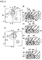
- FIG. 1 shows a locking mechanism of a socket connector of one embodiment of this invention, wherein (A) is a rear view, (B) is a plan view, (C) is a front view, and (D) is a side view.
- FIG. 2 shows a pin connector for connection to the socket connector, wherein (A) is a front view, (B) is a plan view, and (C) is a side view.
- FIG. 3 shows a contact of the socket connector, wherein (A) is a front view, (B) is a side view, (C) is a rear view, and (D) is a bottom view.
- FIG. 4 is sectional views each taken along line E—E in FIG. 1 , (B), wherein (A) shows a non-connected state before fitting of the pin connector and (B) shows a connected state after fitting of the pin connector.
- FIG. 5 is enlarged sectional views of the main part before and after the socket connector and the pin connector are fitted together, wherein (A) shows the state before the fitting and before sliding of an actuator and (B) shows the state after the fitting and after sliding of the actuator.
- FIG. 6 shows the locking mechanism of the socket connector, wherein (A) is a plan view of the non-connected state (open position), (B) is a sectional view taken along line A—A in (A), (C) is a sectional view of the state where an upper cam is pushed into a cover in (B), (D) is a plan view of the connected state (closed position), (E) is a sectional view taken along line B—B in (D), and (F) is a sectional view of the state where the upper cam is restored in (E).
- FIG. 7 is enlarged sectional views each taken along line C—C or line D—D in FIG. 6 , (B), wherein (A) shows the state taken along line C—C (but, the upper cam not illustrated), (B) shows the non-connected state taken along line C—C, (C) shows the connected state taken along line C—C, and (D) shows the state taken along line D—D.
- a connector 1 is a socket connector which is generally called a ZIF connector.
- the socket connector 1 comprises an insulating case 2 , an insulating cover 3 covering the case 2 , and conductive socket contacts 4 retained by the cover 3 .
- the case 2 and the cover 3 are fixed together by a pair of screws 7 .
- the socket contacts 4 have tip portions that are respectively exposed through a plurality of projection holes 3 a provided in the cover 3 .
- the case 2 is provided with a plurality of insertion holes 2 a for inserting a plurality of pin contacts of a pin connector.
- the case 2 and the cover 3 are collectively called an insulator.
- An insulating actuator 5 is slidably mounted in the case 2 .
- the actuator 5 is caused to slide by operation of a cam mechanism 6 .
- the cam mechanism 6 comprises a first cam, i.e. an upper cam 6 a , that is rotatable and insulative and a second cam, i.e. a lower cam 6 b , that is insulative and moves in conjunction with the upper cam 6 a .
- a cylindrical compression coil spring 8 is interposed between the upper cam 6 a and the lower cam 6 b as an elastic member.
- the upper cam 6 a is rotatable about one axis and slidable between first and second positions in a predetermined direction parallel to such one axis.
- the lower cam 6 b is engaged with the upper cam 6 a so as to be rotated in conjunction with the upper cam 6 a.
- FIG. 2 shows a pin connector 11 as a mating connector to be connected to the socket connector 1 .
- the pin connector 11 comprises an insulator 12 and a plurality of pin contacts 13 retained by the insulator 12 .
- Each pin contact 13 has a pin-shaped terminal 13 a projecting from one side of the insulator 12 for connection to a printed board and a thin plate-shaped pin 13 b projecting from the other side of the insulator 12 for connection to the socket contact 4 .
- each socket contact 4 is formed integral and continuous so as to have a stationary portion 4 a to be fixed to the case 2 , a bent portion 4 b bent at a first contact point P, a generally U-shaped portion 4 c , a bent portion 4 d bent at a second contact point P, a movable portion 4 e to be pushed by the actuator 5 , and a terminal portion 4 f projecting from the stationary portion 4 a .
- the first contact point P and the second contact point P face each other so as to provide a gap therebetween.
- guides 4 b 1 and 4 d 1 are symmetrically provided, respectively.
- the guides 4 b 1 and 4 d 1 serve to introduce the pin 13 b of the corresponding pin contact 13 into the gap between the contact points P so that the pin 13 b contacts the contact points P with no insertion force without buckling that is generated due to interference of the pin 13 b with the corresponding socket contact 4 .
- the actuator 5 slides in an arrow direction to a position shown in FIG. 4 , (B).
- the actuator 5 displaces the movable portions 4 e of the socket contacts 4 . That is, the actuator 5 slides following the rotation of the lower cam 6 b to drive the socket contacts 4 , thereby performing switching between a connected state and a non-connected state of the socket connector 1 and the pin connector 11 . Therefore, as will be clear from later description, the contact points P implement a ZIF function of sandwiching under pressure the pin 13 b of each pin contact 13 .
- each socket contact 4 is received in a contact groove 2 c .
- a forward end and a side surface of the stationary portion 4 a are in abutment with a stopper 2 d and a fixing wall 2 e of the case 2 , respectively.
- the movable portion 4 e is received in a driving groove 5 a of the actuator 5 .
- the guides 4 b 1 and 4 d 1 are received in a guide groove 2 f of the case 2 .
- the gap g between the contact points P is designed to be greater than a thickness t of the pin 13 b.
- each socket contact 4 receives a force f 1 from a corner 5 b of an inclined surface of the driving groove 5 a of the actuator 5 , the socket contact 4 is elastically deformed.
- the side surface of the stationary portion 4 a receives a reaction force from the fixing wall 2 e of the case 2 and therefore the contact points P receive forces f 2 and f 3 from both surfaces of the pin 13 b of the pin connector 11 while sandwiching it therebetween under pressure.
- the socket connector 1 has a locking mechanism capable of locking the operation of the cam mechanism 6 . Referring to FIGS. 6 and 7 , the locking mechanism will be described.
- the upper cam 6 a basically has a circular shape in cross-section.
- the upper cam 6 a is mounted so as to be rotatable by 90° between an open position and a closed position.
- the upper cam 6 a has a linear groove, i.e. a minus groove 6 a 1 , at one end in the foregoing predetermined direction, i.e. on the surface operable from the exterior, a pair of to-be-locked bosses 6 a 2 at peripheral symmetrical positions, and an angular boss 6 a 3 at the other end in the predetermined direction, i.e. on the back side.
- the minus groove 6 a 1 enables rotational operation of the upper cam 6 a by the use of a so-called minus driver.
- the to-be-locked bosses 6 a 2 project radially outward and are collectively called a to-be-locked portion herein.
- the angular boss 6 a 3 has a square shape in cross-section.
- the lower cam 6 b is disposed so as to face the upper cam 6 a in the predetermined direction and retained by the case 2 and the cover 3 so as to be rotatable by 90° about the foregoing one axis.
- the lower cam 6 b has an angular hole 6 b 1 on an upper surface thereof, a spring receiving hole 6 b 2 continuous with the angular hole 6 b 1 , and a rotation center hole 6 b 3 on a lower surface thereof.
- the angular boss 6 a 3 of the upper cam 6 a is fitted into the angular hole 6 b 1 of the lower cam 6 b so as to be slidable in the foregoing predetermined direction.
- the upper cam 6 a and the lower cam 6 b are engaged with each other in the rotational direction so as to rotate in conjunction with each other.
- the cam insertion hole 3 b of the cover 3 is provided with clearances 3 b 1 and 3 b 2 .
- the cam insertion hole 3 b is provided with a pair of locking boss grooves 3 b 3 for engagement with the pair of to-be-locked bosses 6 a 2 of the upper cam 6 a at the open position (before fitting) and a pair of locking boss grooves 3 b 4 for engagement therewith at the closed position (after fitting).
- the pair of to-be-locked bosses 6 a 2 differ in phase by 180° while the two pairs of locking boss grooves 3 b 3 and 3 b 4 differ in phase by 90°.
- These locking boss grooves 3 b 3 and 3 b 4 extend in radial directions and are collectively called a locking portion herein.
- the case 2 is provided with an actuator insertion hole 2 b (see FIG. 5 , (B)) for allowing the actuator 5 to slide.
- the actuator 5 is provided with a lower-cam insertion hole 5 c (see FIG. 4 , (A)) for allowing the lower cam 6 b to rotate.
- the case 2 is provided with a support shaft 2 g for receiving the rotation center hole 6 b 3 of the lower cam 6 b fitted therearound.
- the minus driver (not illustrated) is first inserted into the minus groove 6 a 1 of the upper cam 6 a and pushes the upper cam 6 a to the inside of the cam insertion hole 3 b of the cover 3 . Then, the upper cam 6 a causes compression of the compression coil spring 8 to reach the state of FIG. 6 , (C). Therefore, the pair of to-be-locked bosses 6 a 2 are released from the locking engagement with the pair of locking boss grooves 3 b 3 of the cover 3 . In other words, the to-be-locked bosses 6 a 2 escape from the locking boss grooves 3 b 3 .
- case 2 and the cover 3 are in the form of the separate components in this embodiment, it is possible to change the design so that they are formed as a single component.
Landscapes
- Physics & Mathematics (AREA)
- General Physics & Mathematics (AREA)
- Engineering & Computer Science (AREA)
- Automation & Control Theory (AREA)
- Details Of Connecting Devices For Male And Female Coupling (AREA)
- Coupling Device And Connection With Printed Circuit (AREA)
Applications Claiming Priority (3)
| Application Number | Priority Date | Filing Date | Title |
|---|---|---|---|
| JP2003069499A JP3907601B2 (ja) | 2003-03-14 | 2003-03-14 | コネクタのロック機構 |
| JP2003-069499 | 2003-03-14 | ||
| PCT/JP2004/003277 WO2004082081A1 (ja) | 2003-03-14 | 2004-03-12 | 接続状態又は非接続状態をロックできるコネクタ |
Publications (2)
| Publication Number | Publication Date |
|---|---|
| US20060178032A1 US20060178032A1 (en) | 2006-08-10 |
| US7214082B2 true US7214082B2 (en) | 2007-05-08 |
Family
ID=32984618
Family Applications (1)
| Application Number | Title | Priority Date | Filing Date |
|---|---|---|---|
| US10/549,092 Expired - Fee Related US7214082B2 (en) | 2003-03-14 | 2004-03-12 | Connector allowing locking of connected state or non-connected state |
Country Status (5)
| Country | Link |
|---|---|
| US (1) | US7214082B2 (ja) |
| JP (1) | JP3907601B2 (ja) |
| CA (1) | CA2519276C (ja) |
| DE (1) | DE112004000436T5 (ja) |
| WO (1) | WO2004082081A1 (ja) |
Cited By (2)
| Publication number | Priority date | Publication date | Assignee | Title |
|---|---|---|---|---|
| US20100136843A1 (en) * | 2007-08-17 | 2010-06-03 | Yurij Donetsky | Plug-and-socket connector assembly |
| US20240039185A1 (en) * | 2022-07-28 | 2024-02-01 | Micron Technology, Inc. | Connection designs for memory systems |
Citations (15)
| Publication number | Priority date | Publication date | Assignee | Title |
|---|---|---|---|---|
| US4836798A (en) * | 1987-12-21 | 1989-06-06 | Wells Electronics, Inc. | Zero insertion socket with normally closed contacts |
| JPH0429512A (ja) | 1990-05-25 | 1992-01-31 | Mitsubishi Electric Corp | 電気操作装置付挿入形回路遮断器のインターロック装置 |
| US5342213A (en) * | 1992-06-09 | 1994-08-30 | Minnesota Mining And Manufacturing Company | IC socket |
| US5508628A (en) * | 1995-02-01 | 1996-04-16 | Pfaff; Wayne K. | Automated closure test socket |
| US5704800A (en) * | 1995-05-31 | 1998-01-06 | Japan Aviation Electronics Industry, Limited | Electrical connector for connection to LSI package having preloaded and cantilevered plate type contact with L-shape slits for providing two contact points |
| US5727959A (en) * | 1994-11-29 | 1998-03-17 | Yazaki Corporation | Lever fitting-type connector |
| JPH10288345A (ja) | 1997-04-16 | 1998-10-27 | Matsushita Electric Ind Co Ltd | 操作つまみ装置 |
| JP3073936B2 (ja) | 1996-12-26 | 2000-08-07 | 日本航空電子工業株式会社 | コネクタ |
| JP2000286025A (ja) | 1999-03-31 | 2000-10-13 | Japan Aviation Electronics Industry Ltd | 電気コネクタ |
| JP2000306642A (ja) | 1999-04-22 | 2000-11-02 | Japan Aviation Electronics Industry Ltd | Zifコネクタ |
| US6419514B1 (en) * | 2001-04-24 | 2002-07-16 | Hon Hai Precision Ind. Co., Ltd. | ZIF socket |
| US6666691B2 (en) * | 2001-09-14 | 2003-12-23 | Texas Instruments Incorporated | Socket for removably mounting electronic packages |
| JP2004047344A (ja) | 2002-07-15 | 2004-02-12 | Japan Aviation Electronics Industry Ltd | Zifコネクタ |
| US6746262B2 (en) * | 2002-09-09 | 2004-06-08 | Hon Hai Precision Ind. Co., Ltd. | Socket connector with actuator mechanism mating means |
| US6890201B2 (en) * | 2002-07-15 | 2005-05-10 | Japan Aviation Electronics Industry, Limited | ZIF connector having a contact of unique shape |
Family Cites Families (1)
| Publication number | Priority date | Publication date | Assignee | Title |
|---|---|---|---|---|
| JPH0429512Y2 (ja) * | 1986-12-10 | 1992-07-16 |
-
2003
- 2003-03-14 JP JP2003069499A patent/JP3907601B2/ja not_active Expired - Fee Related
-
2004
- 2004-03-12 CA CA002519276A patent/CA2519276C/en not_active Expired - Fee Related
- 2004-03-12 DE DE112004000436T patent/DE112004000436T5/de not_active Withdrawn
- 2004-03-12 WO PCT/JP2004/003277 patent/WO2004082081A1/ja not_active Ceased
- 2004-03-12 US US10/549,092 patent/US7214082B2/en not_active Expired - Fee Related
Patent Citations (15)
| Publication number | Priority date | Publication date | Assignee | Title |
|---|---|---|---|---|
| US4836798A (en) * | 1987-12-21 | 1989-06-06 | Wells Electronics, Inc. | Zero insertion socket with normally closed contacts |
| JPH0429512A (ja) | 1990-05-25 | 1992-01-31 | Mitsubishi Electric Corp | 電気操作装置付挿入形回路遮断器のインターロック装置 |
| US5342213A (en) * | 1992-06-09 | 1994-08-30 | Minnesota Mining And Manufacturing Company | IC socket |
| US5727959A (en) * | 1994-11-29 | 1998-03-17 | Yazaki Corporation | Lever fitting-type connector |
| US5508628A (en) * | 1995-02-01 | 1996-04-16 | Pfaff; Wayne K. | Automated closure test socket |
| US5704800A (en) * | 1995-05-31 | 1998-01-06 | Japan Aviation Electronics Industry, Limited | Electrical connector for connection to LSI package having preloaded and cantilevered plate type contact with L-shape slits for providing two contact points |
| JP3073936B2 (ja) | 1996-12-26 | 2000-08-07 | 日本航空電子工業株式会社 | コネクタ |
| JPH10288345A (ja) | 1997-04-16 | 1998-10-27 | Matsushita Electric Ind Co Ltd | 操作つまみ装置 |
| JP2000286025A (ja) | 1999-03-31 | 2000-10-13 | Japan Aviation Electronics Industry Ltd | 電気コネクタ |
| JP2000306642A (ja) | 1999-04-22 | 2000-11-02 | Japan Aviation Electronics Industry Ltd | Zifコネクタ |
| US6419514B1 (en) * | 2001-04-24 | 2002-07-16 | Hon Hai Precision Ind. Co., Ltd. | ZIF socket |
| US6666691B2 (en) * | 2001-09-14 | 2003-12-23 | Texas Instruments Incorporated | Socket for removably mounting electronic packages |
| JP2004047344A (ja) | 2002-07-15 | 2004-02-12 | Japan Aviation Electronics Industry Ltd | Zifコネクタ |
| US6890201B2 (en) * | 2002-07-15 | 2005-05-10 | Japan Aviation Electronics Industry, Limited | ZIF connector having a contact of unique shape |
| US6746262B2 (en) * | 2002-09-09 | 2004-06-08 | Hon Hai Precision Ind. Co., Ltd. | Socket connector with actuator mechanism mating means |
Cited By (4)
| Publication number | Priority date | Publication date | Assignee | Title |
|---|---|---|---|---|
| US20100136843A1 (en) * | 2007-08-17 | 2010-06-03 | Yurij Donetsky | Plug-and-socket connector assembly |
| US7819682B2 (en) * | 2007-08-17 | 2010-10-26 | Yurij Donetsky | Plug-and-socket connector assembly |
| US20240039185A1 (en) * | 2022-07-28 | 2024-02-01 | Micron Technology, Inc. | Connection designs for memory systems |
| US12355167B2 (en) * | 2022-07-28 | 2025-07-08 | Micron Technology, Inc. | Connection designs for memory systems |
Also Published As
| Publication number | Publication date |
|---|---|
| JP2004281174A (ja) | 2004-10-07 |
| DE112004000436T5 (de) | 2006-02-16 |
| CA2519276C (en) | 2008-09-09 |
| JP3907601B2 (ja) | 2007-04-18 |
| CA2519276A1 (en) | 2004-09-23 |
| US20060178032A1 (en) | 2006-08-10 |
| WO2004082081A1 (ja) | 2004-09-23 |
| WO2004082081A9 (ja) | 2005-05-26 |
Similar Documents
| Publication | Publication Date | Title |
|---|---|---|
| US6168445B1 (en) | Two-part electrical connector | |
| EP1111728B1 (en) | Connector with an improved guide portion for guiding connection of the connector and an object to be connected thereto | |
| US5938470A (en) | Half-fitting prevention connector | |
| US9716341B2 (en) | Lever-type connector assembly | |
| JP4867875B2 (ja) | レバー式コネクタ | |
| US9735503B2 (en) | Connector for receiving and electrically connecting with a cable | |
| EP1882287B1 (en) | Electrical connector with a locking mechanism | |
| US9755361B2 (en) | Lever of the lever-fitting-type connector having a locked part with a convex surface | |
| JP4755539B2 (ja) | コネクタ | |
| KR20120084690A (ko) | 커넥터 | |
| US9112306B2 (en) | Connector | |
| JP4798277B2 (ja) | コネクタ | |
| US7214082B2 (en) | Connector allowing locking of connected state or non-connected state | |
| JP4247920B2 (ja) | レバーコネクタ | |
| US5975930A (en) | Slide fit connector | |
| US6890201B2 (en) | ZIF connector having a contact of unique shape | |
| WO2018061981A1 (ja) | コネクタ組立体 | |
| US7077675B2 (en) | ZIF connector in which a position of a contact is automatically adjusted during a connecting operation | |
| EP1875558B1 (en) | Dual action mechanical assisted connector | |
| EP1905134A1 (en) | Electrical connector | |
| JP3435600B2 (ja) | 板状物用コネクタ | |
| KR101632704B1 (ko) | 커넥터 어셈블리 | |
| JP3812943B2 (ja) | ロック機構付きzifコネクタ | |
| KR100950350B1 (ko) | 이중 작동 기계적 보조 커넥터 | |
| JP2026071796A (ja) | コネクタ |
Legal Events
| Date | Code | Title | Description |
|---|---|---|---|
| STCF | Information on status: patent grant |
Free format text: PATENTED CASE |
|
| FEPP | Fee payment procedure |
Free format text: PAYOR NUMBER ASSIGNED (ORIGINAL EVENT CODE: ASPN); ENTITY STATUS OF PATENT OWNER: LARGE ENTITY |
|
| FPAY | Fee payment |
Year of fee payment: 4 |
|
| FPAY | Fee payment |
Year of fee payment: 8 |
|
| FEPP | Fee payment procedure |
Free format text: MAINTENANCE FEE REMINDER MAILED (ORIGINAL EVENT CODE: REM.); ENTITY STATUS OF PATENT OWNER: LARGE ENTITY |
|
| LAPS | Lapse for failure to pay maintenance fees |
Free format text: PATENT EXPIRED FOR FAILURE TO PAY MAINTENANCE FEES (ORIGINAL EVENT CODE: EXP.); ENTITY STATUS OF PATENT OWNER: LARGE ENTITY |
|
| STCH | Information on status: patent discontinuation |
Free format text: PATENT EXPIRED DUE TO NONPAYMENT OF MAINTENANCE FEES UNDER 37 CFR 1.362 |
|
| FP | Lapsed due to failure to pay maintenance fee |
Effective date: 20190508 |